

Page 1
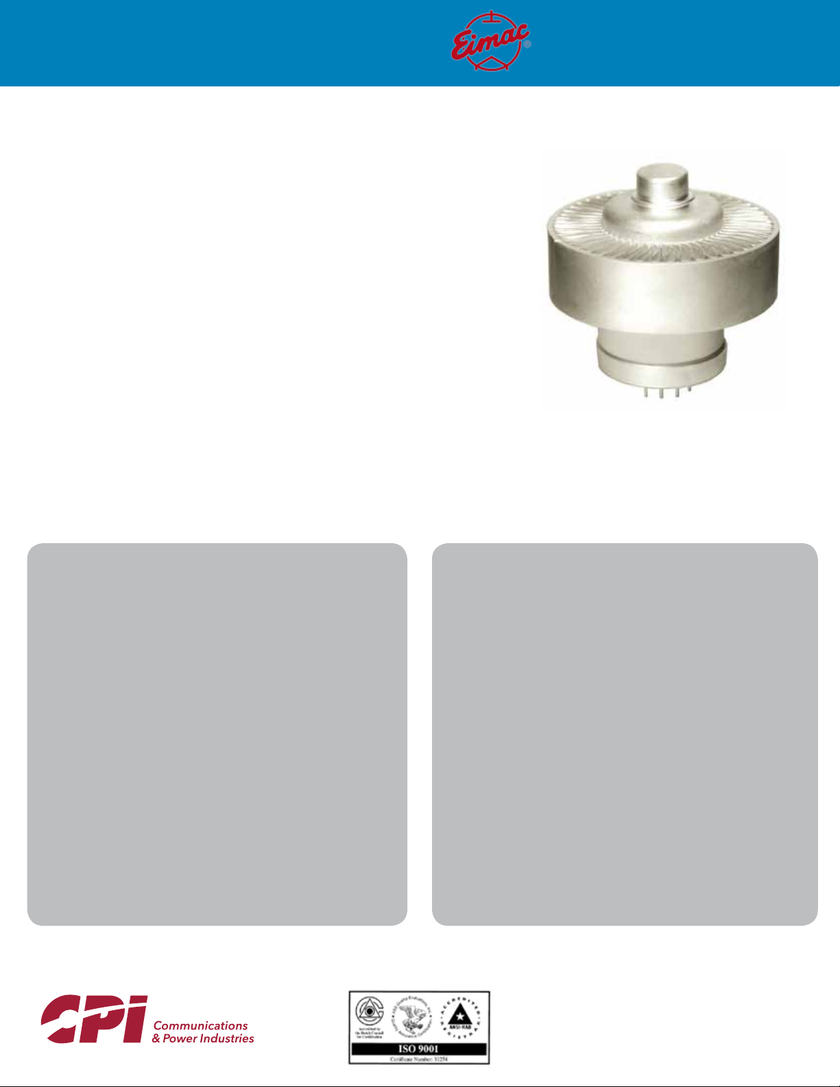
HIGH POWER TRIODE
The EIMAC 3CPX800A7 is a rugged ceramic/metal high-mu power triode designed with beamforming cathode and control-grid geometry to
allow the simplicity of design and circuit advantages of a triode with the gain of a tetrode.
The 3CPX800A7 is intended for pulsed rf amplifier, pulse modulator or pulse regulator service,
with a pulse anode current rating of 8 amperes,
and a maximum anode voltage holdoff rating of
4500 volts.
The anode is forced-air cooled for 800 watts of
dissipation.
3CPX800A7
CHARACTERISTICS
ELECTRICAL:
Cathode: Oxide Coated, Unipotential
Heater Voltage .........................13.5 ± 0.6 V
Heater Current at 13.5 Volts ...............1.5 A
Cathode-Heater Potential (Max.) .....±150 V
Minimum Warm-up Time ...................3 Min.
(before application of rf drive and high voltage)
Amplification Factor (approximate) .................. 200
Direct Interelectrode Capacitances (grounded grid)
Cin ....................................................25.5 pF
Cout ...................................................6.1 pF
Cpk ...................................................0.04 pF
Frequency of Maximum Ratings ..........500 MHz
1
MECHANICAL:
Overall Dimensions:
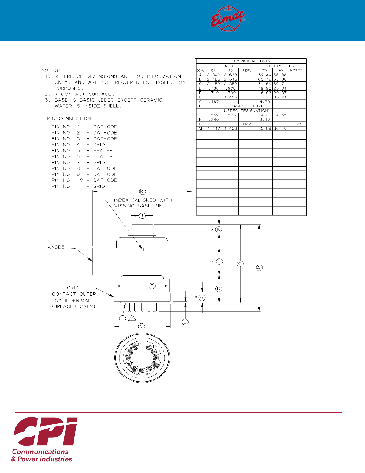
Length .......................... 2.425 in: 61.59 mm
Diameter ....................... 2.530 in; 64.26 mm
Net Weight .............................. 12.0 oz; 340 gm
Operating Position ......................................Any
Maximum Operating Temperature:
Ceramic/Metal Seals or Anode Core.. ... 250° C
2
Cooling ............................................. Forced Air
Base ..... . Large Wafer Elevenar 11-pin with Ring (EIA No. E11-81)
Recommended Socket ...........................Special
Recommended Air Chimney .........Eimac SK-1906
Recommended Chimney Clamp....Eimac SK-1916
1
Characteristics and operating values are based upon performance tests. These figures may change without notice as the result of additional data or product
refinement. CPI MPP Eimac Operation should be consulted before using this information for final equipment design.
2
Capacitance values are for a cold tube as measured in a special shielded fixture in accordance with Electronic Industries Association Standard RS-191.
www.cpii.com/mpp
May 2020
Page 2
3CPX800A7
TYPICAL OPERATION
NOTE: TYPICAL OPERATION data are obtained from direct measurement or by calculation from published characteristic
curves. Adjustment of the rf grid voltage to obtain the specified anode current at the specified bias and anode voltages
is assumed. If this procedure is followed, there will be little variation in output power when the tube is changed, even
though there may be some variation in grid current. The grid current which results when the desired anode current is obtained is incidental and varies from tube to tube. These current variations cause no difficulty so long as the circuit maintains the correct voltage in the presence of the variations in current. If grid bias is obtained principally by means of a grid
resistor, the resistor must be adjustable to obtain the required bias voltage when the correct rf grid voltage is applied.
PULSE MODULATOR OR SWITCH TUBE SERVICE
ABSOLUTE MAXIMUM RATINGS
DC ANODE VOLTAGE...................... 4.5 kV
1
PEAK ANODE CURRENT
............... 8.0 A
PULSE DURATION & DUTY1 .....See Derating Chart
ANODE DISSIPATION...................... 800 W
DC GRID VOLTAGE ........................ -150 V
DC GRID CURRENT (Avg)............. 0.060 A
GRID DISSIPATION ......................... 400 W
HEATER VOLTAGE ...See Heater/Cathode Operation
1
Pulse duration, pulse anode current and duty are interrelated; see
Derating Chart.
2
Approximate value.
PULSED RF AMPLIFIER
Cathode Driven Class AB
ABSOLUTE MAXIMUM RATINGS: (to 500 MHz)
DC ANODE VOLTAGE...................... 3.5 kV
TYPICAL OPERATION - Pulse Modulator Service
ANODE VOLTAGE ......................... 4.5 kVdc
PULSE ANODE CURRENT............... 5.0 a
GRID VOLTAGE ............................. -50 Vdc
PULSE POSITIVE GRID VOLTAGE
2
PULSE GRID CURRENT
................ 200 ma
2
....... 70 v
PULSE DURATION ......................... 10 µSec
DUTY ................................................ 0.005
2
PULSE DRIVING POWER
PULSE OUTPUT POWER
PULSE OUTPUT VOLTAGE
- Drive Pulsed
2
TYPICAL OPERATION - Calculated Data
Class AB2 Cathode Driven - Du = 0.01
............... 25 w
2
................ 20 kw
2
............ 4.0 kv
ANODE VOLTAGE .......................... 3.5 kVdc
ANODE CURRENT (Avg) ................. 0.6 A
1
PEAK ANODE CURRENT
............... 2.5 A
ANODE DISSIPATION (Avg) .............800 W
DC GRID VOLTAGE ........................ -150 V
GRID CURRENT (Avg)..................... 0.06 A
GRID DISSIPATION (Avg) ................ 4.0 W
1
Average during pulse.
2
Approximate value, see VHF Operation.
3
Measured at the load.
CATHODE BIAS VOLTAGE ......... +15.0 Vdc
ZERO-SIGNAL ANODE CURRENT.......... 20 mAdc
PULSE ANODE CURRENT1.............. 2.5 Adc
PULSE POWER INPUT
PULSE GRID CURRENT
1
.......................8.75 kw
2
................. 105 mAdc
PEAK RF CATHODE VOLTAGE ..... 130 v
1,2
PEAK DRIVING POWER
PEAK (USEFUL) POWER OUTPUT
............... 320 w
1,3
......6.0 kw
CATHODE INPUT IMPEDANCE........ 30 Ohms
RESONANT ANODE LOAD IMPEDANCE...660 Ohms
2
Page 3

MECHANICAL
3CPX800A7
MOUNTING & SOCKETING – The tube may be mounted
in any position. If it is to be operated in an inverted (anode down) or horizontal position, the available SK-1916
clamp assembly should be used for reliable retention.
Also available is the SK-1906 chimney which has four 4-40
tapped holes at one end for chassis mounting and four
more 4-40 tapped holes at the other end for optional SK1916 mounting. The combination of the SK-1906 with the
optional SK-1916 clamp makes a rigid mounting assembly
for the 3CPX800A7.
STORAGE – If a tube is to be stored as a spare it should
be kept in its original shipping carton, with the original
packing material, to minimize the possibility of handling
damage. Before storage a new tube should be operated
in the equipment for 100 to 200 hours to establish that
it has not been damaged and operates properly. If the
tube is still in storage 6 months later it should be operated in the equipment for 100 to 200 hours to make sure
there has been no degradation. If operation is satisfactory the tube can again be stored with great assurance of
being a known-good spare.
COOLING - Forced-air cooling must be provided to maintain the anode core and seal temperatures at a safe operating temperature. Cooling data are shown for incoming
cooling air at 25°C and 50°C, and represent the minimum
requirements to limit tube temperatures to 225°C. The
pressure drop figures are approximate and are for the
mounting plate, socket, tube and chimney combination
as would be the case with pressurized-compartment
Cooling Air at 25° C
SEA LEVEL 5000 FEET
Anode
Dissipation
(Watts)
400 6 0.09 7 0.1 0
600 11 0.20 14 0.23
800 19 0.50 23 0.57
Air
Flow
(CFM)
Pressure
Drop
(In. of
Water)
Air
Flow
(CFM)
Pressure
Drop
(In. of
Water)
Cooling Air at 50° C
SEA LEVEL 5000 FEET
Anode
Dissipation
(Watts)
400 8 0.10 10 0 .12
600 16 0.31 19 0.35
800 27 0.79 33 0.88
Air
Flow
(CFM)
Pressure
Drop
(In. of
Water)
Air
Flow
(CFM)
Pressure
Drop
(In. of
Water)
mounting, where air is required to pass through the
chassis slots and through the air chimney to reach the
anode cooler.
Some air from the pressurized compartment passes by
the socket for base cooling. This mounting technique
is effective in the HF region but rf leakage through the
slots may cause amplifier instability or regeneration in
the VHF region. Screening the holes or use of “waveguide-beyond-cutoff” (honeycomb) air vents may be required in the VHF region.
Cooling must be applied before or simultaneously with
electrode voltages, including the heater, and may be
removed simultaneously with them. In all cases temperature of the anode and the ceramic/metal seals is the
limiting factor, and the designer is encouraged to use
temperature-sensitive paint or other temperature sensing devices in connection with any equipment design
before the layout is finalized. It should also be noted
that it is not good practice to operate at, or close to, the
absolute maximum temperature rating for the metal/
ceramic seals. Where long life and consistent performance are factors cooling in excess of minimum requirements is normally beneficial.
ELECTRICAL
ABSOLUTE MAXIMUM RATINGS - Values shown for
each type of service are based on the “absolute system”
and are not to be exceeded under any service conditions. These ratings are limiting values outside which
serviceability of the tube may be impaired. In order
not to exceed absolute ratings the equipment designer
has the responsibility of determining an average design
value for each rating below the absolute value of that
rating by a safety factor so that the absolute values will
never be exceeded under any usual conditions of supply-voltage variation, load variation, or manufacturing
variation in the equipment itself. It dœs not necessarily
follow that combinations of absolute maximum ratings
can be attained simultaneously.
HIGH VOLTAGE - The 3CPX800A7 operates at voltages
which can be deadly, and the equipment must be designed properly and operating precautions must be followed. Equipment must be designed so that no one can
come in contact with high voltages. All equipment must
include safety enclosures for high-voltage circuits and
terminals, with interlock switches to open the primary
circuits of the power supplies and to discharge highvoltage capacitors whenever access doors are opened.
Interlock switches must not be bypassed or “cheated”
to allow operation with access doors open. Always remember that HIGH VOLTAGE CAN KILL.
3
Page 4

3CPX800A7
For pulse modulator or regulator service anode voltage
should not exceed 4.5 kVdc at sea level. This value assumes some safety factor and assumes a clean tube with
no buildup of dirt or grime across the insulating ceramic.
At higher altitudes a reduction in voltage may be required
to preclude the possibility of external tube flashover.
HEATER/CATHODE OPERATION - The rated heater voltage for the 3CPX800A7 is 13.5 volts, as measured at the
base of the tube, and variations should be restricted to
± 0.6 volts for long life and consistent performance.
Pulse current capability of the 3CPX800A7 is dependent
on cathode temperature, which in turn is dependent
on heater voltage. For most consistent performance in
switch tube or modulator service, regulation of the heater voltage to limit variation to plus/minus one percent is
recommended. Heater voltage should be measured with
a known accurate RMS-responding meter.
The maximum heater-cathode voltage for the tube is 150
volts. Any applications which use the tube as a cathode follower or place the load between the cathode and
ground may require that the heater voltage supply be
insulated from ground by a voltage equal to the anode
voltage plus an additional voltage if inductance is present in the load.
CATHODE WARM-UP TIME - In normal service it is recommended the heater voltage be applied for a minimum
of three minutes before anode voltage and/or rf drive
voltage are applied, to allow for proper conditioning of
the cathode surface.
INPUT CIRCUIT - When the 3CPX800A7 is operated as
a grounded-grid rf amplifier, the use of a resonant tank
in the cathode circuit is recommended to obtain greatest linearity and power output. For best results with a
single-ended amplifier, it is suggested that the cathode tank circuit operate with a “Q” of two or more.
GRID OPERATION - The maximum rated dc grid bias
voltage for the 3CPX800A7 is -150 volts and the maximum grid dissipation is 4 watts. In normal applications
the grid dissipation will not approach the maximum rating. In applications where pulse duration exceeds 100
Ms or duty factors are high, the electrode dissipation ratings may prevent attaining peak anode current substantially over the dc rating. A protective spark gap, such as
a Siemens #B1-C75, should be connected between the
cathode and grid to provide protection in the event of an
internal tube arc.
ANODE CURRENT - For pulse service, either as a switch
tube pulse modulator or voltage regulator, an anode current (during the pulse) of up to 8 amperes is available.
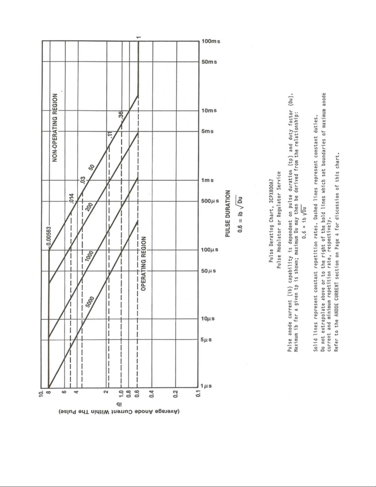
Peak current capability, pulse duration, and duty factors are interrelated and the PULSE DERATING DATA on
page 6 should be consulted.
To use this chart, enter with pulse duration and note the
intersection with desired pulse anode current. At this intersection read off values of maximum duty and/or pulse
repetition rate.
The pulse derating chart is intended to allow selection of
operating parameters which give a reasonable tube life.
Operating under experimental combinations of maximum
anode current and pulse duration which are outside the
ranges of the chart may give useful results at low repetition rates, with a resulting tube life commensurate with
that type of operation.
ANODE OPERATION - The anode of the 3CPX800A7 is
nominally rated for 800 watts with forced-air cooling. In
pulse service the average anode dissipation may be calculated as the product of pulse anode current, pulse tubevoltage drop during conduction, and the duty factor. Actual dissipation may often exceed the calculated value, if
pulse rise and fall times are appreciable compared to pulse
duration. This occurs because long rise and fall times allow
anode current to flow for longer periods in the high tubevoltage drop region.
FAULT PROTECTION - All power tubes operate at voltages which can cause severe damage in the event of an arc,
especially in cases where large amounts of power supply
stored energy are involved. Some means of protection is
advised in all cases, and it is recommended that a series
resistor be used in the lead from the power supply to the
anode circuit to limit peak current and help dissipate the
energy in the event of a tube or circuit arc. A resistance
of 10 to 50 ohms, depending on allowable voltage drop,
with at least a 50W rating, in the positive anode power
supply lead will help protect the tube in the event of an
arc. Eimac application Bulletin #17, FAULT PROTECTION,
contains considerable detail and is available upon request.
VHF OPERATION - The base pin connections to the
grid may be used at frequencies to 30 MHz. Above
30 MHz the available contact collets or grid by-pass
capacitor assembly are recommended. VHF driving power will be greater than the typical values
shown on page 2 because of higher circuit losses.
INTERELECTRODE CAPACITANCE - The actual internal interelectrode capacitance of a tube is influenced by many
variables in most applications, such as stray capacitance to
the chassis, capacitance added by the socket used, stray
capacitance between tube terminals, and wiring effects.
To control the actual capacitance values within the tube,
as the key component involved, the industry and the Military Services use a standard test procedure as described in
Electronic Industries Association Standard RS-191. This requires the use of specially constructed test fixtures, which
effectively shield all external tube leads from each other
and eliminates any capacitance reading to ‘ground’. The
test is per formed on a cold tube in a special shielded fixture.
4
Page 5

3CPX800A7
Other factors being equal, controlling internal tube capacitance in t his way normally assure s good interchange ability of tub es over a period of time, even when the tube
may be made by different manufacturers. The capacitance values shown in the manufacturer’s technical data, or test specifications, normally are taken in
accordance with Standard RS-191. The equipment
designer is therefore cautioned to make allowance for
the actual capacitance values which will exist in any
normal application. Measurements should be taken
with mounting which represents approximate final layout if capacitance values are highly significant in the
design.
RF RADIATION - Avoid exposure to strong rf fields even
at relatively low frequency. Absorption of rf energy by
human tissue is dependent on frequency. Under 300
MHz most of the energy will pass completely through
the human body with little attenuation or heating affect. Public health agencies are concerned with the
hazard, and the published OSHA (Occupational Safety
and Health Administration) or other local recommendations to limit prolonged exposure of rf radiation
should be followed. It is worth noting that some
commercial dielectric heating units actually operate
at frequencies as low as the 13 and 27 MHz bands.
Many Eimac power tubes such as this are specifically designed to generate or amplify radio frequency
power. There may be a relatively strong rf field in the
general proximity of the power and its associated circuitry - the more power involved the stronger the rf
field. Proper enclosure design and efficient coupling
of rf energy to the load will minimize the rf field in the
vicinity of the power amplifier itself.
HOT SURFACES - Air-cooled surfaces and other parts
of tubes can reach temperatures of several hundred
degrees C and cause serious burns if touched for several minutes after all power is removed.
SPECIAL APPLICATIONS - If it is desired to operate this tube under conditions widely different from
those given here, contact the Application Engineering
Dept., CPI MPP Eimac Operation for information and
recommendations.
OPERATING HAZARDS
Proper use and safe operating practices with respect to power tubes are the responsibility of equipment manufacturers and users of such tubes. All persons who work with and are exposed to power tubes, or equipment that
utilizes such tubes, must take precautions to protect themselves against possible serious bodily injury. DO NOT
BE CARELESS AROUND SUCH PRODUCTS.
The operation of this tube may involve the following hazards, any one of which, in the absence of safe operating
practices and precautions, could result in serious harm to personnel.
Please review the detailed Operating Hazards Sheet enclosed with each tube, or request a copy from CPI Microwave Power Products, Eimac Operation.
HIGH VOLTAGE – Normal operating voltages can
be deadly. Remember the HIGH VOLTAGE CAN
KILL.
LOW-VOLTAGE HIGH-CURRENT CIRCUITS - Personal jewelry, such as rings, should not be worn
when working with filament contacts or connectors
as a short circuit can produce very high current and
melting, resulting in severe burns.
RF RADIATION – Exposure to strong rf fields should
be avoided, even at relatively low frequencies.
CARDIAC PACEMAKERS MAY BE AFFECTED.
HOT WATER – Water used to cool tubes may reach
scalding temperatures. Touching or rupture of the
cooling system can cause serious burns.
HOT SUR FACES – Surfaces of tubes can reach
temperatures of several hundred°C and cause serious burns if touched for several minutes after all
power is removed.
MATERIALS COMPLIANCE - This product and
package conforms to the conditions and limitations specified in 49CFR 173.424 for radioactive
material, excepted package-instruments or articles, UN2910. In addition, this product and package contains no beryllium oxide (BeO).
5
Page 6
3CPX800A7
6
Page 7
3CPX800A7
7
Page 8
HIGH-MU POWER TRIODE
3CPX800A7
Microwave Power
Products Division
For more detailed information, please refer to the corresponding CPI
technical description if one has been published, or contact CPI. Specifications
may change without notice as a result of additional data or product refinement.
Please contact CPI before using this information for system design.
©2020 Communications & Power Industries LLC. Company proprietary: use and
reproduction is strictly prohibited without written authorization from CPI.
 Loading...