

Page 1
05113
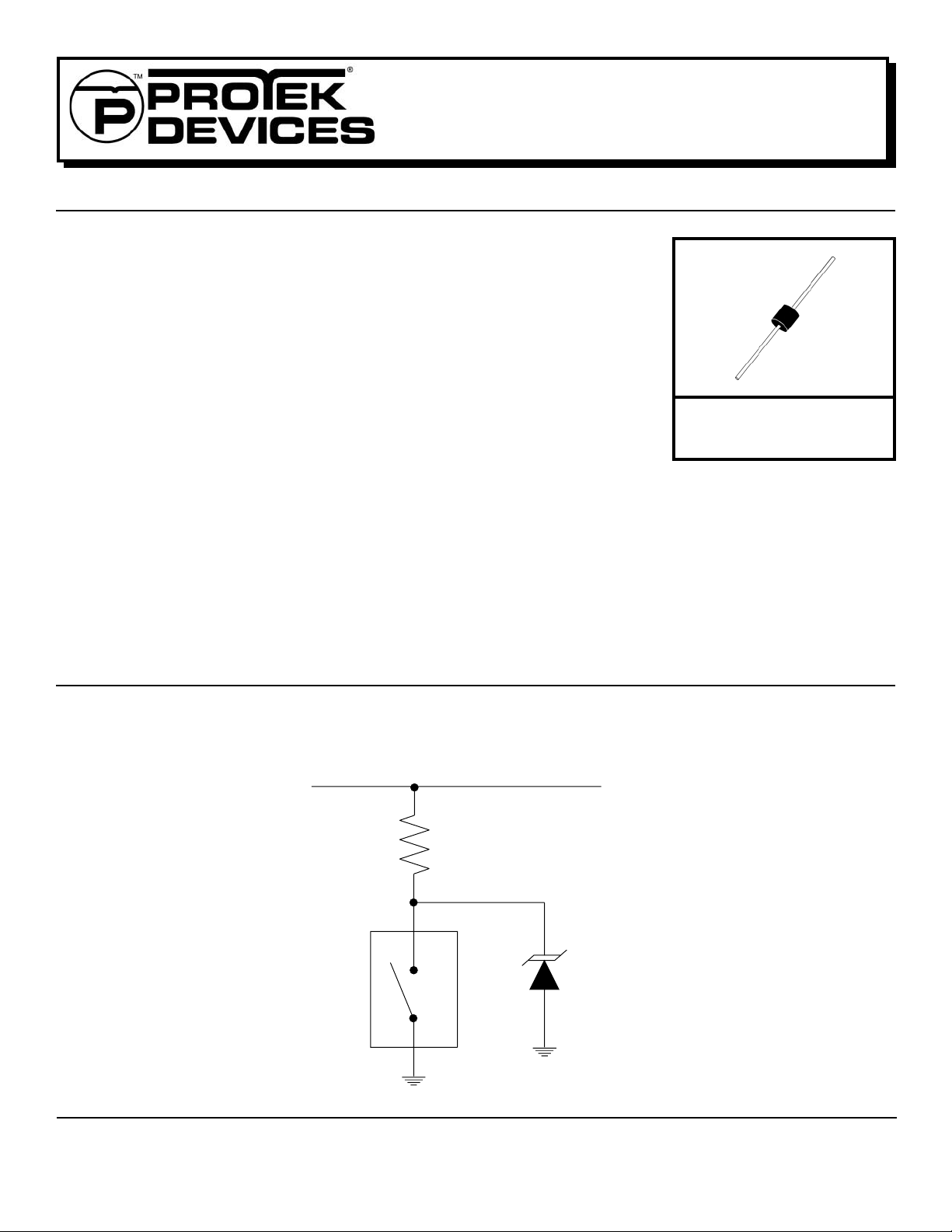
30KPA30A
thru
. . . engineered solutions for the transient environment™
30KPA280A
POWER TVS COMPONENT
APPLICATIONS
✔ Relay Drives
✔ Motor (Start/Stop) Back EMF Protection
✔ Module Lightning Protection
IEC COMPATIBILITY (EN61000-4)
✔ 61000-4-5 (Surge): 8/20µs - 95A, L4 (Line-Gnd), 167A, L3 (P ower) & 48A, L4 (Line-Line)
FEATURES
✔ 30,000 Watts Peak Pulse Power per Line (10/1000µs)
✔ Unidirectional & Bidirectional Configurations
✔ Easy Mounting to Printed Circuit Boards
✔ A v ailable in Voltage Types Ranging From: 30V to 280V
MECHANICAL CHARACTERISTICS
✔ Molded Case
✔ Weight 2.5 grams (Approximate)
✔ Flammability Rating UL 94V -0
✔ P ositiv e Terminal Marked with Band -
✔ Marking: Logo & P art Number
Unidirectional Devices
AXIAL LEAD
05113.R7 9/02
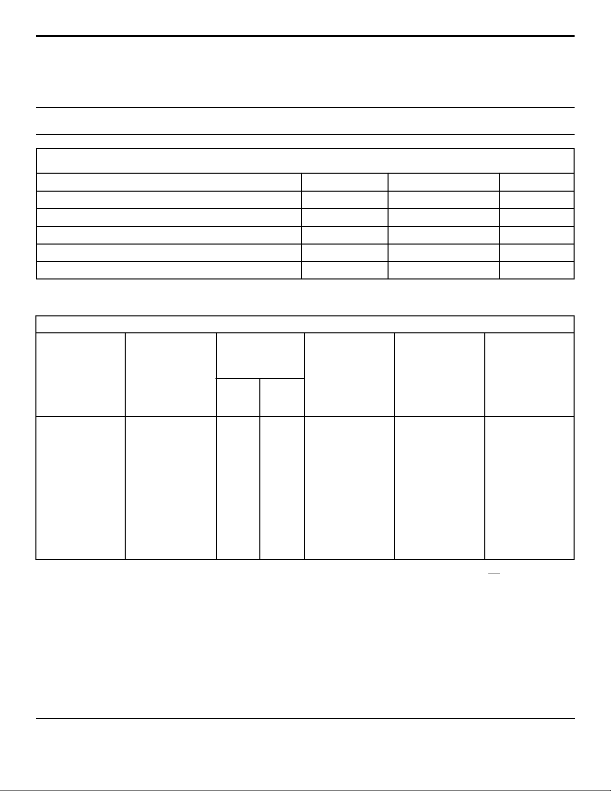
APPLICATION
TYPICAL RELAY DRIVE PROTECTION
V
CC
1
www.protekdevices.com
Page 2
DEVICE CHARACTERISTICS
MAXIMUM RATINGS @ 25°C Unless Otherwise Specified
30KPA30A
thru
30KPA280A
PARAMETER
P eak Pulse P ower Dissipation (tp =10/1000µs) - See Fig. 1
Forward Surge Rating (1/20 seconds) - See Note 2
Steady State Po wer Dissipation
Storage T emperature
Operating T emperature
ELECTRICAL CHARACTERISTICS
PART
NUMBER
(Notes 1 & 2)
30KPA30A
30KPA36A
30KPA43A
30KPA48A
30KPA64A
30KPA70A
30KPA75A
30KPA90A
30KPA160A
30KPA180A
30KPA260A
30KPA280A
RATED
STAND-OFF
VOLTAGE
V
WM
VOLTS
30.0
36.0
43.0
48.0
64.0
70.0
75.0
90.0
160.0
180.0
260.0
280.0
BREAKDOWN
VOLTAGE
MIN
V
(BR)
VOLTS
33.3
40.0
47.8
53.3
71.1
77.8
83.3
100.0
178.0
200.0
289.0
311.0
@I
mA
50
50
50
5
5
5
5
5
5
5
5
5
SYMBOL VALUE
P
PP
I
F
D
T
STG
J
MAXIMUM
LEAKAGE
CURRENT
@V
WM
T
I
µA
D
5000
2000
1000
250
10
10
10
10
10
10
10
10
30,000
1.0
-55 to +150
-55 to +150
MAXIMUM
CLAMPING
VOLTAGE
(See Fig. 2)
@ 10/1000µs
@ I
V
C
PP
55.2V @ 543.0A
61.8V @ 485.0A
73.0V @ 410.0A
77.4V @ 388.0A
104.0V @ 294.0A
109.0V @ 274.0A
119.4V @ 251.0A
147.0V @ 206.0A
252.6V @ 119.0A
291 @ 104A
416.0V @ 72.0A
464.0V @ 65.0A
UNITS
Watts
Amps200
WattsP
0
C
0
CT
TEMPERATURE
COEFFICIENT
OF V
(BR)
θV
(BR)
mV/°C
34
41
50
56
76
83
89
109
195
230
317
342
Note 1: Part numbers shown are unidirectional devices. Add a “CA” suffix to specify bidirectional devices, such as 30KPA30CA.
are preferred voltages. Contact factory for additional voltages.
Note 2: VF = 15 Volts @ 200A, 8.3ms (1/2 Sine Wave) -
unidirectional devices only
2 www.protekdevices.com05113.R7 9/02
.
Devices shown
Page 3

GRAPHS
30KPA30A
thru
30KPA280A
PEAK PULSE POWER VS PULSE TIME
FIGURE 1
1,000
100
10
- Peak Pulse Power - kilowatts
PP
P
0
0.1 1 10 100 1,000 10,000 100,000
t
- Pulse Duration - µs
d
FIGURE 2
100
PP
50
PULSE WAVE FORM
t
f
Peak V alue I
PP
td = t
TEST
WA VEFORM
PARAMETERS
tf = 10µs
td = 1,000µs
IPP/2
30kW 10/1000µs
Waveform
POWER DERATING CURVE
100
80
60
40
FIGURE 3
Peak Pulse Power
10/1000µs
- Peak Pulse Current - % of I
PP
I
0
0 1 2 3
t - Time - ms
% Of Rated Power
20
-t
e
3 www.protekdevices.com05113.R7 9/02
0
0 25 50 75 100 125 150
Average Power
- Lead Temperature - °C
T
L
Page 4

PACKAGE OUTLINE & DIMENSIONS
30KPA30A
thru
30KPA280A
PACKAGE OUTLINE
A
E
B
D
C
30KPA
PACKAGE DIMENSIONS
MILLIMETERS
DIM MIN MAX MIN MAX
A
B
C
D
E
NOTES:
1. Dimensions are exclusive of mold flash and metal
burrs.
24.5
8.60
24.5
1.20 DIA
8.60
06028 Rev 0 - 12/01
-
9.10
-
1.30 DIA
9.10
INCHES
1.00
0.34
1.00
0.048 DIA
0.34
-
0.36
-
0.052 DIA
0.36
Protek Devices
2929 South Fair Lane, Tempe, AZ 85282
T el: 602-431-8101 F ax: 602-431-2288
E-Mail: sales@protekdevices.com
Web Site: www.protekdevices.com
COPYRIGHT © ProTek Devices 2002
SPECIFICA TIONS: ProT ek reserves the right to change the electrical and or mechanical characteristics described herein without notice (except JEDEC).
DESIGN CHANGES: ProTek reserves the right to discontinue product lines without notice, and that the final judgement concerning selection and specifications is the buyer’ s and that in furnishing engineering and
technical assistance, ProT ek assumes no responsibility with respect to the selection or specifications of such products.
4 www.protekdevices.com05113.R7 9/02
 Loading...