

Page 1
Bulletin I2118 rev. B 07/97
FAST SOFT RECOVERY
RECTIFIER DIODE
Description/Features
The 30EPF.. & 30CPF.. soft recovery QUIET
rectifier series has been optimized for combined
short reverse recovery time and low forward voltage
drop.
The glass passivation ensures stable reliable
operation in the most severe temperature and power
cycling conditions.
Typical applications are:
Output rectification and freewheeling in
inverters, choppers and converters
and input rectifications where severe
restrictions on conducted EMI should be met.
30CPF series is a drop in replacement
for 25CPF Series (parallel connection only)
IR
QUIET
IR
Series
30EPF .. 30CPF..
V
t
V
F
rr
RRM
< 1.2V @ 10A
= 60ns
200 to 600V
Major Ratings and Characteristics
Characteristics 30EPF.. Units
30CPF..
I
Sinusoidal waveform 30 A
F(AV)
V
RRM
I
FSM
VF@ 10 A, TJ = 25°C 1.2 V
trr @ 1A, 100A/µs 60 ns
T
J
200 to 600 V
350 A
- 40 to 150 °C
Package Outline
30EPF..
30CPF..
TO-247AC (Modified)
1
Page 2
30EPF .. 30CPF.. QUIET
ta tb
trr
t
Ifm
dir
dt
Qrr
Irm (REC)
IR
Series
Bulletin I2118 rev. B 07/97
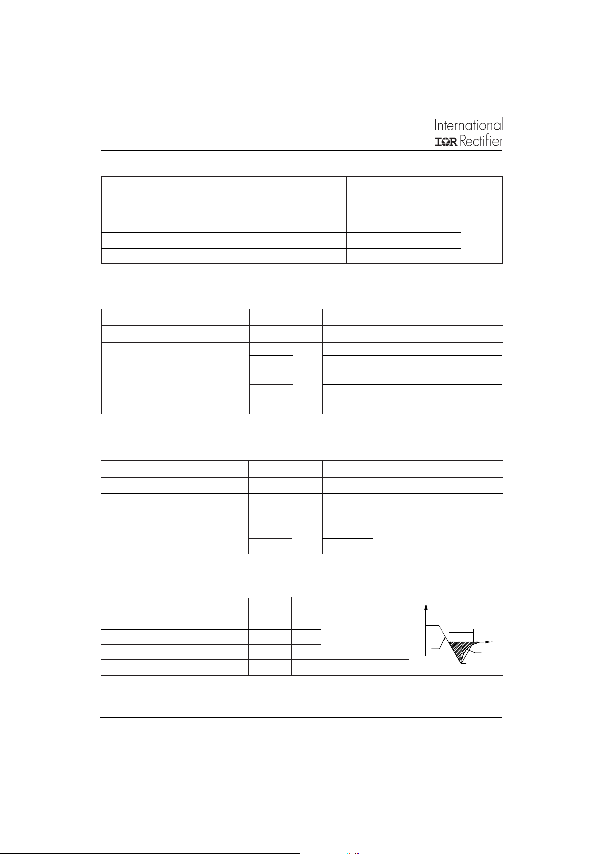
Voltage Ratings
V
Part Number
, maximum V
RRM
peak reverse voltage peak reverse voltage 1 50 °C
, maximum non repetitive I
RSM
VVmA
30EPF02, 30CPF02 20 0 30 0 2
30EPF04, 30CPF04 40 0 50 0
30EPF06, 30CPF06 60 0 70 0
Absolute Maximum Ratings
Parameters 3 0. PF. . Units Conditions
I
Max. Average Forward Current 30 A @ TC = 98° C, 180° conduction half sine wave
F(AV)
Max. Peak One Cycle Non-Repetitive 300 10ms Sine pulse, rated V
I
FSM
Surge Current 350 10ms Sine pulse, no voltage reapplied
I2t Max. I2t for fusing 450 10ms Sine pulse, rated V
A
A2s
636 10ms Sine pulse, no voltage reapplied
2
I
√t Max. I2√t for fusing 6360 A2√s t = 0.1 to 10ms, no voltage reapplied
RRM
RRM
applied
applied
RRM
Electrical Specifications
Parameters 30 .PF .. Units Conditions
VFMMax. Forward Voltage Drop 1.41 V @ 30A, TJ = 25°C
r
Forward slope resistance 12.5 mΩ
t
V
Threshold voltage 0.9 V
F(TO)
IRMMax. Reverse Leakage Current 0.1 TJ = 25 °C
2.0 TJ = 150 °C
TJ = 150°C
mA
Typical Recovery Characteristics
Parameters 3 0. PF. . Units Conditions
trrReverse Recovery Time 160 ns IF @ 20Apk
IrrReverse Recovery Current 10 A @ 100A/ µs
QrrReverse Recovery Charge 1.25 µC @ 25°C
S Snap Factor tb/ta 0.6 typical
2
VR = rated V
RRM
Page 3
30EPF .. 30CPF .. QUIET
Thermal-Mechanical Specifications
Parameters 30.PF.. Units Conditions
TJMax. Junction Temperature Range - 40 to 150 °C
T
Max. Storage Temperature Range - 40 to 150 °C
stg
R
Max. Thermal Resistance Junction 0.8 °C/W DC operation
thJC
to Case
R
Max. Thermal Resistance Junction 40 °C/W
thJA
to Ambient
R
Typical Thermal Resistance, Case to 0.2 °C/W Mounting surface , smooth and greased
thCS
Heatsink
wt Approximate Weight 6 (0.21) g (oz.)
T Mounting Torque Min. 6 (5)
Max. 12 (10)
Case Style TO-247AC JEDEC (Modified)
Kg-cm
(Ibf-in)
IR
Series
Bulletin I2118 rev. B 07/97
150
140
130
120
110
100
90
Maximum Allowable Ca se Temperature (°C)
0 5 10 15 20 25 30 35
30EPF.. Series
R (DC) = 0.8 K/W
thJC
Conduction Angle
30°
60°
90°
Average Forward Cu rre nt (A)
120°
180°
150
140
130
120
110
100
90
Ma ximum Allowable Ca se Tempe rature (°C)
0 5 10 15 20 25 30 35 40 45 50
30EPF.. Se ries
R (DC) = 0.8 K/W
thJC
Conduction Period
30°
60°
90°
120°
Averag e Forwar d Cu rre nt (A)
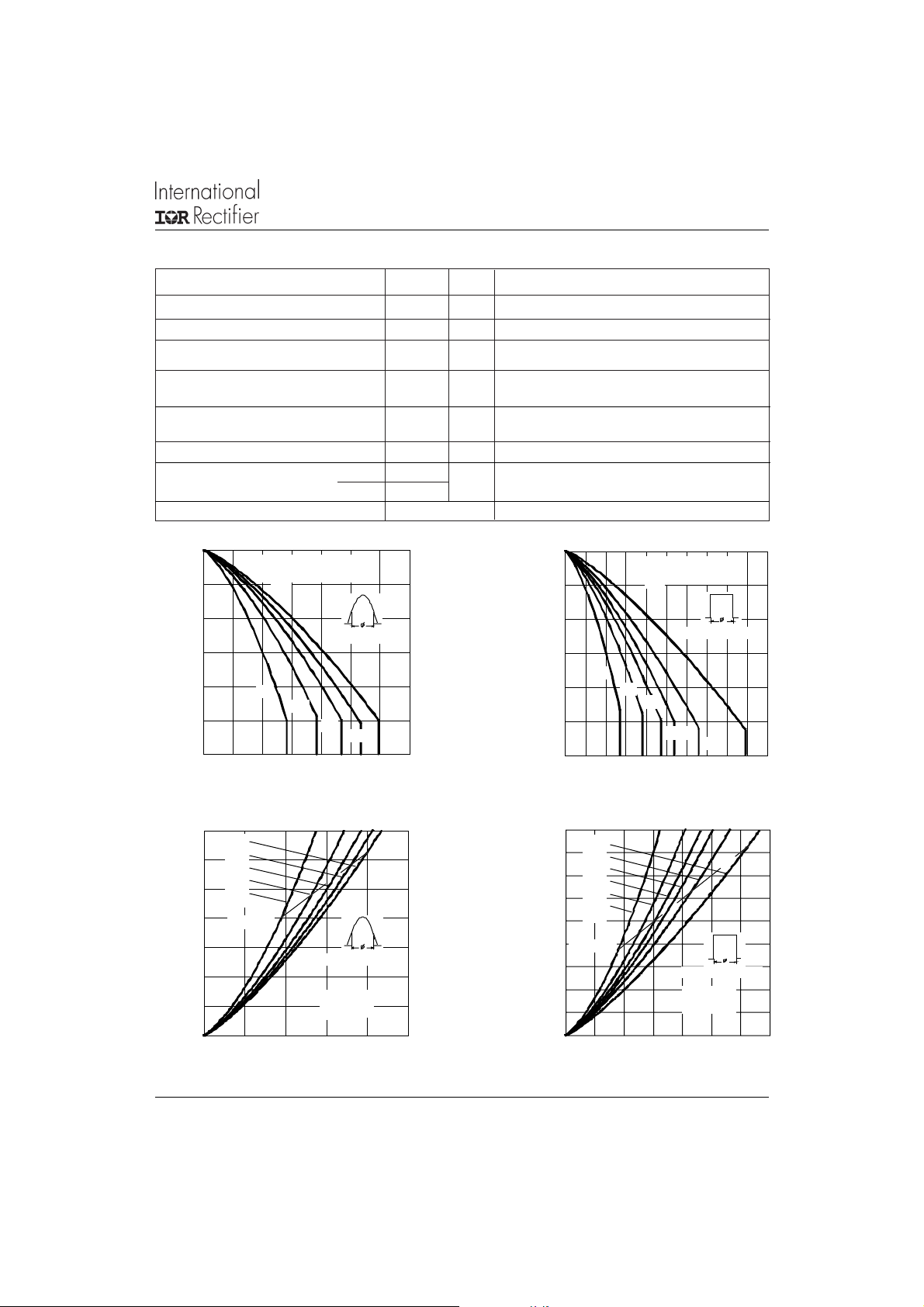
Fig. 1 - Current Rating Characteristics Fig. 2 - Current Rating Characteristics
35
180°
120°
30
90°
60°
25
30°
20
RMS Lim it
15
10
5
0
Maximum Average Forward Power Loss (W)
0 5 10 15 20 25
Average Forward Current (A)
Conduction Angle
30EPF..
T = 150°C
J
45
DC
40
180°
120°
35
90°
30
60°
30°
25
20
RMS Lim it
15
10
5
0
Maximum Aver age Forward Power Loss (W)
0 5 10 15 20 25 30 35
Average Forward Current (A)
Conduction Period
30EPF..
T = 1 5 0°C
J
Fig. 3 - Forward Power Loss Characteristics Fig. 4 - Forward Power Loss Characteristics
180°
DC
3
Page 4

30EPF .. 30CPF.. QUIET
Bulletin I2118 rev. B 07/97
IR
Series
350
At Any Rated Load Condition And Wit h
Rated V A pplied Following Surge.
300
250
200
150
100
30EPF..Series
50
Peak Hal f Sine Wave Forward Current (A)
1 10 100
Number Of Equal Ampli tude Half Cycle Current Pulse s (N)
RRM
Initial T = 150°C
J
@ 60 Hz 0.0083 s
@ 50 Hz 0.0100 s
Fig. 5 - Maximum Non-Repetitive Surge Current
1000
100
10
Instantan eous Forwar d Current (A)
1
012345
Instantaneous Forward Voltage (V)
Fig. 7 - Forward Voltage Drop Characteristics
T = 25°C
J
T = 150°C
J
30EPF.. Series
400
Maximum Non Re p et itive Surge Current
350
300
250
200
150
100
50
30EPF.. Series
Peak Half Sine Wav e Forward Current (A)
0
0.01 0.1 1 10
Versus Pulse Tr ain Duration.
Pulse Train Duration (s)
Initi al T = 150°C
No Voltage Reapplied
Rated V Reapplied
RRM
J
Fig. 6 - Maximum Non-Repetitive Surge Current
0.2
I = 30 A
0.15
0.1
0.05
Ma ximum Rev erse Recovery Time - Trr (µs)
0
0 200 400 600 800 1000
Rate Of Fall Of Forward Current - di/dt (A/µs)
TM
20 A
10 A
4
30EPF ..
T = 25 °C
J
5 A
1 A
0.5
30EPF..
0.4
0.3
I = 30 A
0.2
0.1
Maximum Reverse Recove ry Time - Trr ( µs)
0
0 200 400 600 800 1000
Rate Of Fall Of Forward Current - di/dt (A/µs)
TM
T = 150 °C
20 A
10 A
Fig. 9 - Recovery Time Characteristics, TJ = 150°CFig. 8 - Recovery Time Characteristics, TJ = 25°C
J
5 A
1 A
Page 5

30EPF .. 30CPF .. QUIET
)
Bulletin I2118 rev. B 07/97
IR
Series
3.5
4
3
30EPF..
T = 25 °C
J
I = 30 A
TM
20 A
2.5
2
10 A
1.5
1
0.5
0
0 200 400 600 800 1000
Maximum Reverse Re co very Charge - Qrr (µC)
5 A
1 A
Rate Of Fall Of Forward Current - di/dt (A /µs)
Fig. 10 - Recovery Charge Characteristics, TJ = 25°C
70
60
50
40
30
20
10
30EPF ..
T = 25 °C
J
I = 30 A
TM
20 A
10 A
5 A
1 A
10
30EPF..
9
8
T = 150 °C
J
I = 30 A
7
6
5
4
3
2
1
0
0 200 400 600 800 1000
Maximum Reverse Recovery Charge - Qrr (µC)
Rate Of Fall Of Forward Current - di/dt (A/µs)
Fig. 11 - Recovery Charge Characteristics, T
100
30EPF..
80
60
40
20
T = 150 °C
J
I = 30 A
TM
TM
J
20 A
10 A
5 A
1 A
= 150°C
20 A
10 A
5 A
1 A
0
Maximum Reverse Re c o very Current - Irr (A
0 200 400 600 800 1000
Rate Of Fall O f Forw ard Current - di/dt (A/µs)
Fig. 12 - Recovery Current Characteristics, T
10
D = 0.50
D = 0.33
thJC
D = 0.25
D = 0.17
1
D = 0.08
0.1
Sing le Puls e
Trans ie nt Ther mal Im pe danc e Z (K/W)
0.01
0.0001 0.001 0.01 0.1 1
Fig. 14 - Thermal Impedance Z
= 25°C
J
Squar e Wav e Pulse Duration (s)
Fig. 13 - Recovery Current Characteristics, T
Characteristics
thJC
0
Maximum Reverse Reco very Current - Irr (A)
0 200 400 600 800 1000
Rate Of Fall Of Forward Current - di/dt (A/µs)
Stea d y State Va lue
(DC Operation)
30EPF.. Series
= 150°C
J
5
Page 6

30EPF .. 30CPF.. QUIET
1
CATHODE
ANODE
3
2
BASE
CATHODE
Bulletin I2118 rev. B 07/97
Outline T able
IR
Series
15.90 (0 .626)
15.30 (0 .602)
20.30 (0 .800)
19.70 (0 .775)
1 3
14.80 (0.583)
14.20 (0 .559)
1.40 (0.056)
1.00 (0.039)
10. 9 4 ( 0.4 30 )
10.86 (0.427 )
Ordering Information Table
Device Code
3. 65 ( 0 . 14 4 )
3. 55 ( 0 . 13 9 )
5.70 (0.225)
5.3 0 ( 0.2 08 )
4.30 (0.170)
3.70 (0.145)
2.20 (0.087)
MAX.
DIA.
5.5 0 ( 0.2 17 )
4.50 (0.177)
(2 PLCS.)
5.30 (0.209)
4.70 (0.185)
Dimensions in millimeters and inches
2.5 (0.098)
1.5 (0.059)
2.40 (0.095)
MAX.
0.80 (0.032)
0.40 (0.213)
30 E P F 06
1
3
1 - Current Rating
2 - Circuit Configuration:
E = Single Diode
3 - Package:
P = TO-247AC (Modified)
4 - Type of Silicon:
F = Fast Recovery
5 - Voltage code: Code x 100 = V
6
524
RRM
02 = 200V
04 = 400V
06 = 600V
6
Page 7

Outline T able
30EPF .. 30CPF .. QUIET
Bulletin I2118 rev. B 07/97
IR
Series
20.30 (0 .800)
19.70 (0 .775)
14.80 ( 0.583)
14.20 (0 .559)
1.40 (0 .056)
1.00 (0 .039)
10.94 ( 0.430)
10.86 (0 .427)
15.90 (0 .626 )
15.30 (0 .602 )
123
4.30 (0.170)
3.70 (0.145)
Dimensions in millimeters and inches
3.65 (0.144)
3.55 (0.139)
5. 70 (0.22 5)
5.30 (0.208)
5.50 ( 0.217)
4. 50 (0.17 7)
(2 PLCS.)
2. 20 (0.087)
MAX.
DIA.
5. 30 (0.20 9)
4.70 (0.185)
0.80 (0.032)
0. 40 (0.21 3)
2.5 (0.098)
1.5 (0.059)
2. 40 (0.095)
MAX.
Ordering Information Table
Device Code
30 C P F 06
1 5243
1 - Current Rating
2 - Circuit Configuration:
C = Single Diode, 3 pins
3 - Package:
P = TO-247AC
4 - Type of Silicon:
F = Fast Recovery
5 - Voltage code: Code x 100 = V
6
RRM
BASE
CATHODE
2
13
ANODE ANODE
02 = 200V
04 = 400V
06 = 600V
7
 Loading...