

Datasheet 300HFR80PS, 300HFR80PB, 300HFR80P, 300HFR80MS, 300HFR80MB Datasheet (International Rectifier)
...Page 1
Bulletin I2021/A
Next Data SheetIndex
Previous Datasheet
To Order
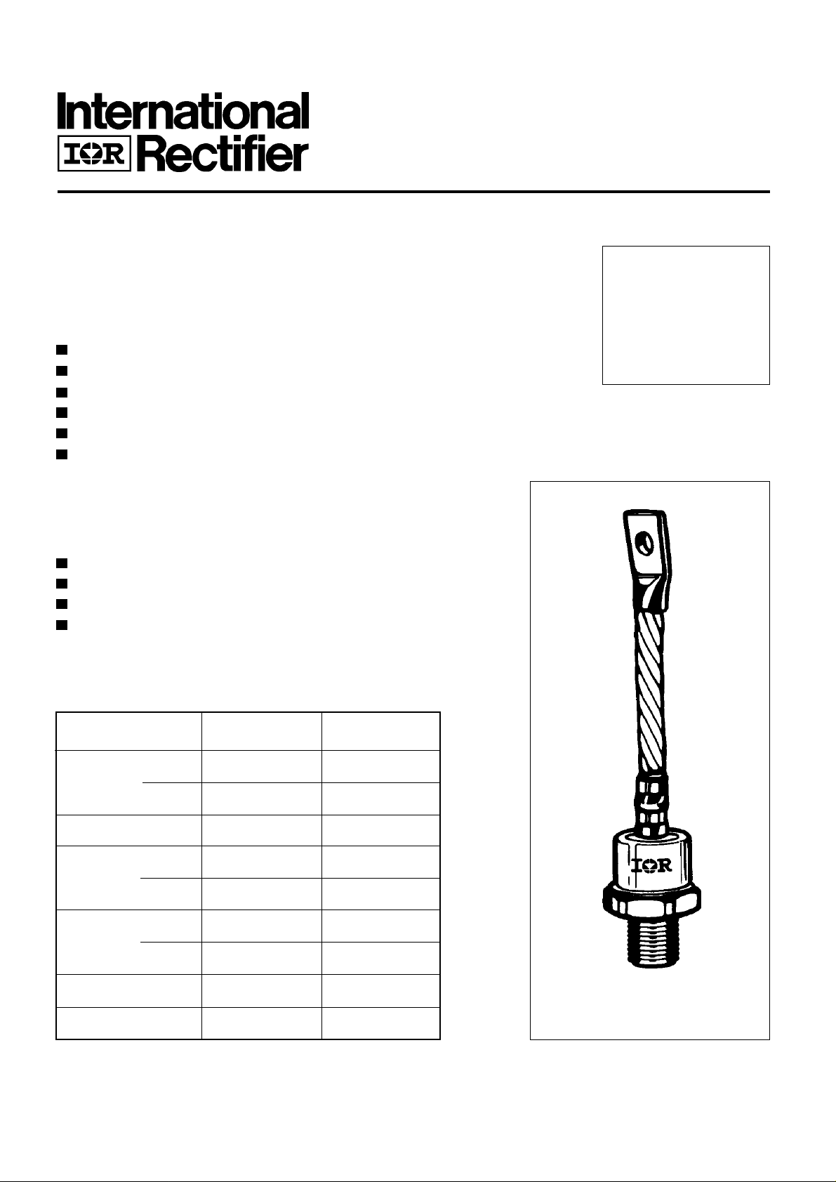
300HF(R) SERIES
STANDARD RECOVERY DIODES Stud Version
Features
High current carrying capability
High surge current capability
Types up to 1200V V
Stud cathode and stud anode version
Standard JEDEC types
Diffused junction
RRM
T ypical Applications
Battery chargers
Converters
Power supplies
Machine tool controls
Major Ratings and Characteristics
300A
Parameters 300HF(R) Units
I
F(AV)
@ T
C
I
F(RMS)
I
FSM
I2t@
V
range 400 to 1200 V
RRM
T
J
@ 50Hz 5000 A
@ 60Hz 5200 A
50Hz 125 KA2s
@ 60Hz 113 KA2s
300 A
125 °C
470 A
case style
DO-205AB (DO-9)
-40 to 180 °C
Page 2
300HF(R) Series
To Order
Next Data SheetIndex
Previous Datasheet
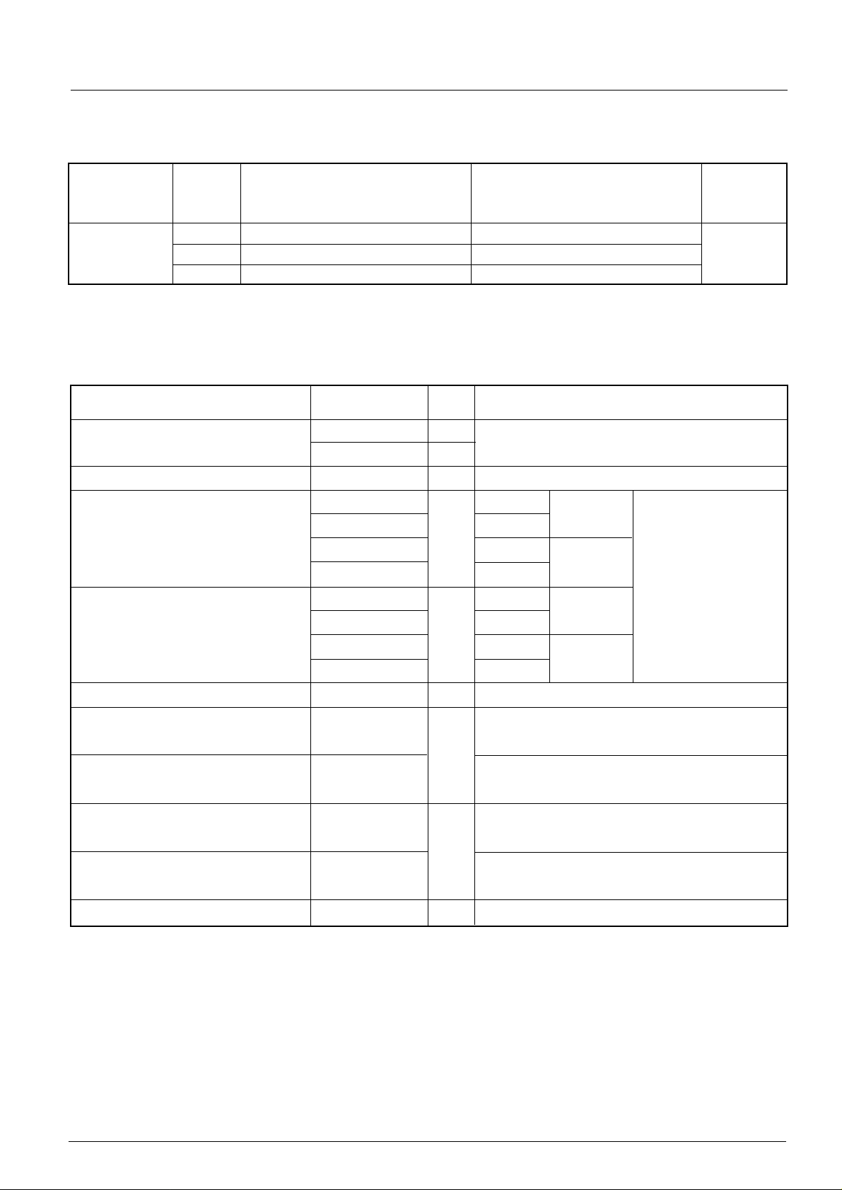
ELECTRICAL SPECIFICATIONS
Voltage Ratings
Voltage V
Type number Code peak voltage repetitive peak voltage @ 180°C
40 400 500
300HF(R) 80 800 900 20
120 1200 1300
Forward Conduction
Parameter 300HF(R) Units Conditions
, maximum repetitive V
RRM
VVmA
, maximum non- I
RSM
RRM
max.
I
F(AV)
Max. average forward current 300 A 180° conduction, half sine wave
@ Case temperature 125 °C
I
F(RMS)
I
FSM
Max. RMS forward current 470 A DC @ 118°C case temperature
Max. peak, one-cycle forward, 5000 t = 10ms No voltage
non-repetitive surge current 5200 t = 8.3ms reapplied
A
3800 t = 10ms 100% V
RRM
4000 t = 8.3ms reapplied Sinusoidal half wave,
2
I
t Maximum I2t for fusing 125 t = 10ms No voltage Initial TJ = TJ max
113 t = 8.3ms reapplied
KA2s
72 t = 10ms 100% V
RRM
66 t = 8.3ms reapplied
2
√t Maximum I2√t for fusing 1250 KA2√s t = 0.1 to 10ms, no voltage reapplied
I
V
V
r
f1
r
f2
V
Low level value of threshold
F(TO)1
voltage
High level value of threshold
F(TO)2
0.86 (16.7% x π x I
V
0.89 (I > π x I
voltage
Low level value of forward
slope resistance
High level value of forward
0.48 (16.7% x π x I
mΩ
0.46 (I > π x I
slope resistance
Max. forward voltage drop 1.38 V IFM= π x I
FM
< I < π x I
F(AV)
), TJ = TJ max.
F(AV)
< I < π x I
F(AV)
), TJ = TJ max.
F(AV)
, TJ = 25 °C, tp = 10ms sinusoidal wave
F(AV)
), TJ = TJ max.
F(AV)
), TJ = TJ max.
F(AV)
Page 3

Thermal and Mechanical Specification
To Order
Next Data SheetIndex
Previous Datasheet
Parameter 300HF(R) Units Conditions
T
Max. operating temperature range -40 to 180
J
Max. storage temperature range -55 to 180
T
stg
Max. thermal resistance, junction to case 0.12 DC operation
R
thJC
Max. thermal resistance, case to heatsink 0.05 Mounting surface, smooth, flat and greased
R
thCS
T Max. allowed mounting torque +0 -20% 28 Not lubricated threads
22 Lubricated threads
wt Approximate weight 250 g
Case style DO-205AB(DO-9) See Outline Table
°C
K/W
Nm
300HF(R) Series
∆R
(The following table shows the increment of thermal resistence R
Conduction
thJC
when devices operate at different conduction angles than DC)
thJC
Conduction angle Sinusoidal conduction Rectangular conduction Units Conditions
180° 0.030 0.022 T
120° 0.035 0.037
90° 0.045 0.048 K/ W
60° 0.064 0.066
30° 0.104 0.105
= TJ max.
J
Ordering Information Table
Device Code
300 HF R 120 P B
1 4
1 - Essential Part Number
2
3
5
6
2 - Diode
3 - None = Stud Normal Polarity (Cathode to Stud)
R = Stud Reverse Polarity (Anode to Stud)
4 - Voltage code: Code x 10 = V
5 - P = Stud base DO-205AB(DO-9) 3/4" 16UNF-2A
M = Stud base DO-205AB(DO-9) M16 x 1.5
6 - B = Flag top terminals (for Cathode/ Anode Leads)
S = Isolated lead with silicone sleeve
None = Not isolated lead
(See Voltage Ratings table)
RRM
(Red = Reverse Polarity; Blue = Normal Polarity)
Page 4

300HF(R) Series
To Order
Next Data SheetIndex
Previous Datasheet
Outline Table
GLASS-METAL SEAL
DIA. 28.5 (1.08) MAX.
200 (7.87) ± 1 0 ( 0. 39)
75 (2.95 ) MIN.
MAX.
28.5 (1.12)
MAX.
21 (0.82)
9.5 (0.37) MIN.
DIA. 8.5 (0.33) NOM.
MAX.
10 (0.39)
19 (0.75)
MAX.
C.S. 25mm
(0.039 s.i.)
SW 32
4 (0.16) MAX.
MAX.
39 (1.53)
2
Conform to JEDEC DO-205AB (DO-9)
All dimensions in millimeters (inches)
3/4-16UNF-2A*
* FOR METRIC DEVICE: M16 X 1.5
DO-205AB (DO-9) Flag
All dimensions in millimeters (inches)
GLASS-METAL SEAL
DIA. 28.5 (1.12) MAX.
70 (2.75) MAX.
MAX.
28.5 (1.12)
21 (0.83)
MAX.
10 (0.39)
MAX.
21 (0.83)
14 (0.55)
DIA. 6.5 (0.26)
13 (0.51)
62 (2.44)
3/4"-16UNF-2A*
*FOR METRIC DEVICE: M16 X 1.5
3 (0.12)
32 (1.26)
Page 5

300HF(R) Series
To Order
Next Data SheetIndex
Previous Datasheet
180
300H F (R) S eries
R (DC) = 0.1 2 K/W
170
thJC
160
Conduction Angle
150
140
30°
60°
90°
120°
130
120
Maxi mum Allowabl e C ase Temperature (°C)
0 50 100 150 200 250 300 350
Average Fo rwar d Cu rrent (A)
Fig. 1 - Current Ratings Characteristics
400
180°
350
120°
90°
300
60°
30°
250
RM S Limit
200
150
100
50
180°
Conduction Angle
300HF(R ) Series
T = 180 °C
J
180
170
300HF(R ) Series
R (DC) = 0 .1 2 K/W
thJC
160
150
Conduction Peri od
140
130
90°
120
110
M ax i m um Allowable Case Temperatu r e ( ° C)
0 100 200 300 400 500
30°
60°
120°
180°
DC
Average Fo rwar d C urrent ( A)
Fig. 2 - Current Ratings Characteristics
0
0
.
0
.
4
K
/
0
.
5
K
/
0
.
6
K
/
0
.
8
K
/
1
.
2
K
/
.
2
3
W
W
W
W
W
K
/
W
0
.
R
1
K
K
/
W
t
h
/
W
S
A
=
0
.
0
5
K
/
W
D
e
l
t
a
R
0
Maximum Average Fo rward Power Loss (W)
0 50 100 150 200 250 300 350
600
500
400
300
RM S Limit
200
100
0
M aximum Average Forward Powe r Loss (W)
0
Average For ward Curr ent (A)
Fig. 3 - Forward Power Loss Characteristics
DC
180°
120°
90°
60°
30°
Conduction Period
300HF(R) Series
T = 180°C
J
100 200 300 400 500
Average Forward C urre n t ( A)
0 20 40 60 80 100 120 140 160 180
Maxi mu m All owable Ambient Temperat u re (°C )
0
.
1
R
K
t
/
h
W
S
A
0
.
2
K
/
W
0
.
3
K
/
W
0
.
4
K
/
W
0
.
6
K
/
W
0
.
8
K
/
W
1
.
2
K
/
W
=
0
.
0
5
K
/
W
-
D
e
l
t
a
R
0 20 40 60 80 100 120 140 160 180
M aximum Allowable A mbie nt Te m perature (°C )
Fig. 4 - Forward Power Loss Characteristics
Page 6

300HF(R) Series
To Order
Next Data SheetIndex
Previous Datasheet
4500
4000
3500
3000
2500
2000
1500
Peak Half Si ne Wave For w ard Current (A )
1000
Number Of Equal Amplitude Half Cycle Curr ent Pul ses (N)
At Any Rated Load Conditio n An d With
Rated V Applied Fol lowing Surge .
300HF(R) Series
1 10 100
RRM
Initial T = 180 °C
J
@ 60 H z 0.0083 s
@ 50 H z 0.0100 s
10000
Peak H alf Si ne Wave Forward Curr ent (A)
5500
5000
4500
4000
3500
3000
2500
2000
1500
1000
Maximum Non Repetitive Sur ge Current
Versus Pulse Tra in Duration.
Initial T = 180°C
No Volt age Reapplie d
Rated V Reapplied
300HF(R) Series
0.01 0.1 1
Pulse Train D uration ( s)
Fig. 6 - Maximum Non-Repetitive Surge CurrentFig. 5 - Maximum Non-Repetitive Surge Current
RRM
J
1000
T = 25°C
J
T = 180°C
100
Instantaneous Forward Curr ent (A)
10
0.511.522.533.5
Instantaneous Forward Voltage (V )
Fig. 7 - Forward Voltage Drop Characteristics
1
thJC
0.1
Steady State Value:
R = 0.12 K/W
thJC
( D C O peration)
J
300HF(R) Serie s
0.01
Transient Thermal Impedance Z (K/W)
0.001
0.001 0.01 0.1 1 10
Square Wave Pulse Duration (s)
Fig. 8 - Thermal Impedance Z
300HF(R) Series
Characteristic
thJC
 Loading...