

Page 1
2N6897
-12A, -100V, P-Channel Enhancement Mode
December 2001
Power MOS Field Effect Transistor
Features
• -12A, -100V
•r
DS(ON)
• SOA is Power Dissipation Limited
• Nanosecond Switching Speeds
• Linear Transfer Characteristics
• High Input Impedance
• Majority Carrier Device
= 0.3 Ω
Ordering Information
PART NUMBER PACKAGE BRAND
2N6897 TO-204AA 2N6897
NOTE: When ordering, include the entire part number.
Packaging
Description
The 2N6897 is an P-Channel enhancement mode silicon
gate power MOS field effect transistor designed for applications such as switching regulators, switching converters,
motor drivers, relay drivers, and drivers for high power bipolar switching transistors requiring high speed and low gate
drive power. This device can be operated directly from an
integrated circuit.
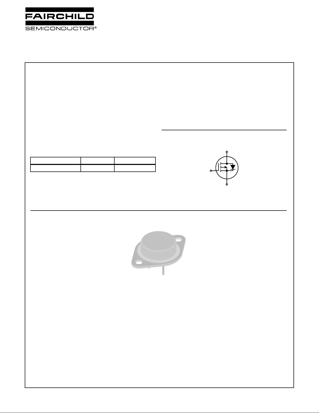
Symbol
D
G
S
JEDEC TO-204AA
©2001 Fairchild Semiconductor Corporation 2N6897 Rev. B
Page 2
µ
µ
Ω
Ω
2N6897
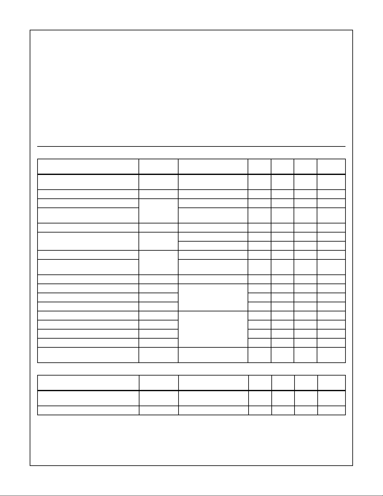
Absolute Maximum Ratings
o
T
= 25
C, Unless Otherwise Specified
C
2N6897 UNITS
Drian to Source Voltage . . . . . . . . . . . . . . . . . . . . . . . . . . . . . . . . . . . . . . . . . . . . . . . . BV
Drian to Gate Voltage (R
Continuous Drain Current
= 1 ΜΩ) . . . . . . . . . . . . . . . . . . . . . . . . . . . . . . . . . . . . . . . . .V
GS
RMS Continuous. . . . . . . . . . . . . . . . . . . . . . . . . . . . . . . . . . . . . . . . . . . . . . . . . . . . . . . . .I
Pulsed Drain Current. . . . . . . . . . . . . . . . . . . . . . . . . . . . . . . . . . . . . . . . . . . . . . . . . . . . I
Gate to Source Voltage . . . . . . . . . . . . . . . . . . . . . . . . . . . . . . . . . . . . . . . . . . . . . . . . . . . . V
Maximum Power Dissipation
Operating and Storage Junction Temperature Range . . . . . . . . . . . . . . . . . . . . . . . . T
T
= 25
C
Above T
o
C . . . . . . . . . . . . . . . . . . . . . . . . . . . . . . . . . . . . . . . . . . . . . . . . . . . . . . . . . . . . . P
o
= 25
C, Derate Linearly . . . . . . . . . . . . . . . . . . . . . . . . . . . . . . . . . . . . . . . . . . . . 0.8 W/
C
Maximum Lead Temperature for Soldering. . . . . . . . . . . . . . . . . . . . . . . . . . . . . . . . . . . . . . T
(At distance 1/8 in. (3.17mm) from seating plane for 10s max)
CAUTION: Stresses above those listed in “Absolute Maximum Ratings” may cause permanent damage to the device. This is a stress only rating and operation of
the device at these or any other conditions above those indicated in the operational sections of this specification is not implied.
Electrical Specifications
o
T
= 25
C, Unless Otherwise Specified
C
DSS
DGR
D
DM
GS
D
, T
J
STG
L
-100 V
-100 V
-12 A
-30 A
±20 V
100 W
-55 to 150
260
o
C
o
C
o
C
TEST
PARAMETER SYMBOL
Drian to Source
BV
Breakdown Voltage
Gate to Threshold Voltage V
GS(TH)
Zero-Gate Voltage Drain Current I
Zero-Gate Voltage Drain Current
T
= 125
C
o
C
Gate to Source Leakage Current I
Drian to Source On-Voltage (Note 1) V
Static Drian to Source On Resistance (Note 1) r
Static Drian to Source On Resistance
T
= 125
C
o
C (Note 1)
DS(ON)
DS(ON)
Forward Transconductance (Note 1) g
Input Capacitance C
Output Capacitance C
Reverse-Transfer Capacitance C
Turn-On Delay Time t
d(ON)
Rise Time t
Turn-Off Delay Time t
d(OFF)
Fall Time t
Thermal Resistance
R
Junction-to-Case
DSS
DSS
GSS
fs
ISS
OSS
RSS
r
f
JC
θ
CONDITIONS MIN TYP MAX UNITS
I
= 1mA, V
D
V
= V
GS
V
= -80V - - 1
DS
V
= -80V - - 50
DS
V
= ±20V, V
GS
I
= 7.6A, V
D
I
=12A, V
D
I
= 7.6A, V
D
I
= 7.6A, V
D
I
= 7.6A, V
D
V
= 0V, V
GS
f = 0.1MHz
= 0V -100 - - V
GS
, I
= 0.25mA -2 - -4 V
DS
D
= 0V - - 100 nA
DS
= -10V - - 2.28 V
GS
= -10V - - -4.8 V
GS
= -10V - - 0.3
GS
= 10V - - 0.465
GS
= -10V 2 - 8 S
DS
DS
= -25V
400 - 1500 pF
200 - 700 pF
60 - 240 pF
I
= 7.6A, V
D
R
GEN
V
GS
= -10V
= R
DS
GS
= -50V
= 15 Ω ,
- - 60 ns
- - 175 ns
- - 275 ns
- - 175 ns
- - 1.25
o
A
A
C/W
Source to Drain Diode Specifications
TEST
PARAMETER SYMBOL
Diode Forward Voltage (Note 1) V
Diode Reverse Recovery Time t
SD
rr
NOTE:
4. Pulsed: pulse duration = 300 µ s, max, duty cycle = 2%.
©2001 Fairchild Semiconductor Corporation 2N6897 Rev. B
CONDITIONS MIN TYP MAX UNITS
I
= 12A 0.8 - 1.6 V
SD
I
= 4A, d
F
/dt = 100A/ µ s - - 500 ns
IF
Page 3
100
10
1
0.01
1 10 100 1000
I
D
, DRAIN CURRENT (A)
OPERATION IN THIS AREA
LIMITED BY r
DS(ON)
VDS, DRAIN TO SOURCE (V)
100µs
1.0ms
10ms
100ms
DC
V
DSS
(MAX) = 100V
TC = 25oC
TJ = MAX RATED
r
DS(ON)
, DRAIN TO SOURCE ON
ID, DRAIN CURRENT (A)
0.4
0.2
0.1
0
02 6 101418
RESISTANCE (Ω)
-40oC
25oC
125oC
0.3
20
4 8 12 16
VGS = 10V
PULSE TEST
PULSE DURATION = 80µs
DUTY CYCLE ≤ 2%
1
0.9
-50 0 50 100 150
T
J,
JUNCTION TEMPERATURE (oC)
V
GS(TH)
, NORMALIZED GATE
THRESHOLD VOLTAGE (V)
1.2
1.1
0.8
0.7
VDS = V
GS
ID = 0.25mA
1.3
2N6897
Typical Performance Curves
1.2
1.0
0.8
0.6
0.4
0.2
POWER DISSIPATION MULTIPLIER
0.0
0 25 50 75 100 150
TC, CASE TEMPERATURE (oC)
Unless Otherwise Specified
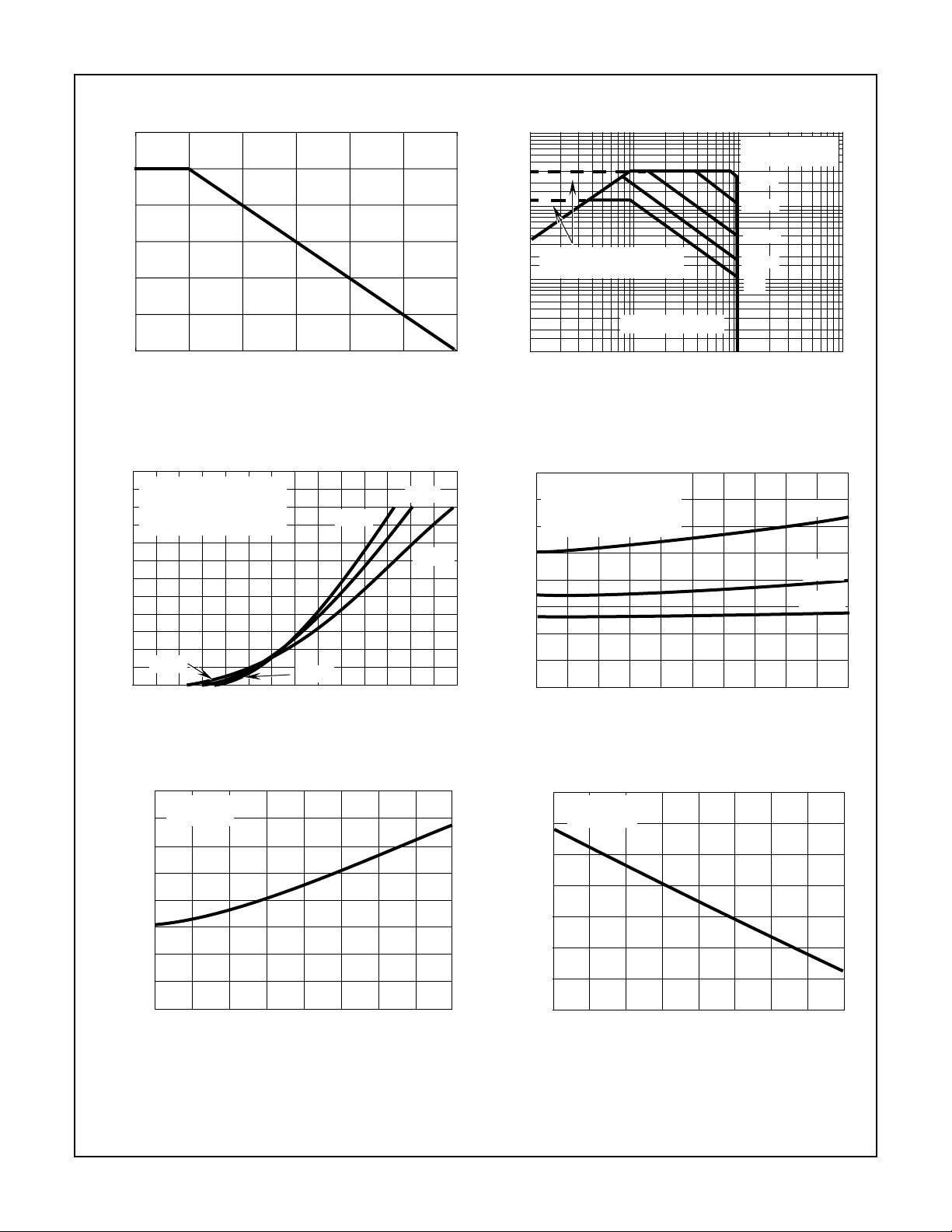
FIGURE 15. NORMALIZED POWER DISSIPATION vs
TEMPERATURE DERATING CURVE
24
V
= 10V
DS
PULSE TEST
20
PULSE DURATION = 80µs
DUTY CYCLE ≤ 2%
16
12
-40oC
125
FIGURE 16. MAXIMUM OPERATING AREAS CURVE
25oC
125oC
8
4
, ON-STATE DRAIN CURRENT (A)
125oC
d(ON)
I
0
-1 -2 -3 -4 -5 -8
V
GATE TO SOURCE VOLTAGE (V)
GS,
-40oC
FIGURE 17. TRANSFER CHARACTERISTICS FIGURE 18. DRAIN TO SOURCE ON RESISTANCE AS A FUNC-
2.0
1.5
1.0
0.5
©2001 Fairchild Semiconductor Corporation 2N6897 Rev. B
ON RESISTANCE (mΩ)
NORMALIZED DRAIN TO SOURCE
FIGURE 19. NORMALIZED r
= 7.6A
I
D
VGS = 10V
0
-50 0 50 100 150
T
, JUNCTION TEMPERATURE (oC)
J
TEMPERATURE
DS(ON)
vs JUNCTION
-6 -7
TION OF DRAIN CURRENT
FIGURE 20. NORMALIZED GATE THRESHOLD VOLTAGE vs
JUNCTION TEMPERATURE
Page 4
t
ON
t
d(ON)
t
r
90%
10%
V
DS
90%
10%
t
f
t
d(OFF)
t
OFF
90%
50%
50%
10%
PULSE WIDTH
V
GS
2N6897
Typical Performance Curves Unless Otherwise Specified (Continued)
2400
2000
1600
1200
800
F, CAPACITANCE (C)
P
400
01020304050
VDS, DRAIN TO SOURCE VOLTAGE (V)
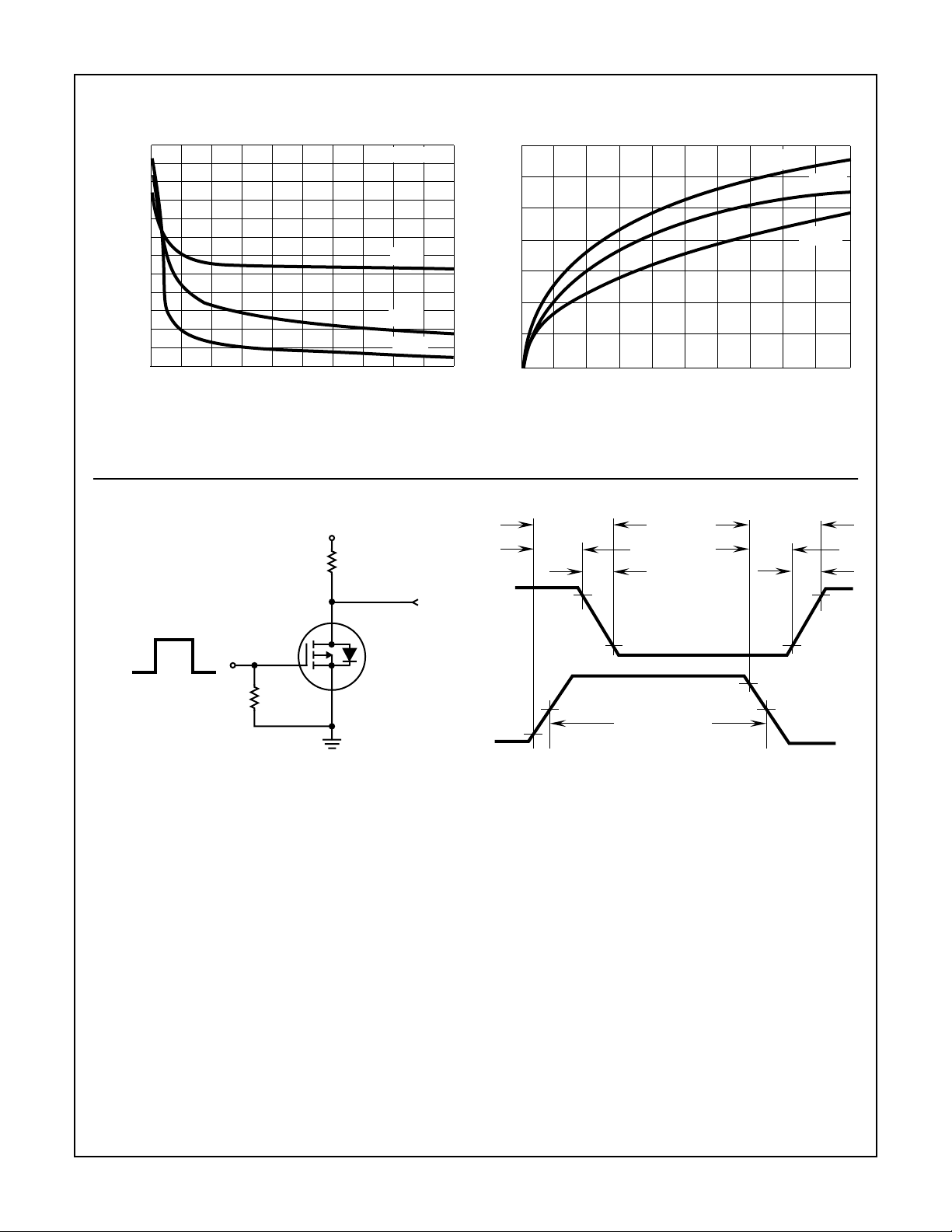
FIGURE 21. CAPACITANCE vs VOLTAGE
Test Circuit and Waveforms
V
DD
f = 1MHz
C
ISS
C
OSS
C
RSS
7
6
5
4
3
2
1
, FORWARD TRANSCONDUCTANCE (S)
fs
g
0
012 345
ID, DRAIN CURRENT (A)
-40oC
25oC
125oC
678 910
FIGURE 22. FORWARD TRANSCONDUCTANCE AS A
FUNCTION OF DRAIN CURRENT
R
L
V
DS
V
GS
0V
R
GS
DUT
FIGURE 23. RESISTIVE SWITCHING TEST CIRCUIT FIGURE 24. RESISTIVE SWITCHING WAVEFORMS
©2001 Fairchild Semiconductor Corporation 2N6897 Rev. B
Page 5

TRADEMARKS
The following are registered and unregistered trademarks Fairchild Semiconductor owns or is authorized to use and is
not intended to be an exhaustive list of all such trademarks.
ACEx™
Bottomless™
CoolFET™
CROSSVOLT™
DenseTrench™
DOME™
EcoSPARK™
E2CMOS
EnSigna
TM
TM
FACT™
FACT Quiet Series™
STAR*POWER is used under license
FAST
FASTr™
FRFET™
GlobalOptoisolator™
GTO™
HiSeC™
ISOPLANAR™
LittleFET™
MicroFET™
MicroPak™
MICROWIRE™
OPTOLOGIC™
OPTOPLANAR™
PACMAN™
POP™
Power247™
PowerTrench
QFET™
QS™
QT Optoelectronics™
Quiet Series™
SILENT SWITCHER
SMART START™
STAR*POWER™
Stealth™
SuperSOT™-3
SuperSOT™-6
SuperSOT™-8
SyncFET™
TinyLogic™
TruTranslation™
UHC™
UltraFET
VCX™
DISCLAIMER
FAIRCHILD SEMICONDUCTOR RESERVES THE RIGHT TO MAKE CHANGES WITHOUT FURTHER
NOTICE TO ANY PRODUCTS HEREIN TO IMPROVE RELIABILITY, FUNCTION OR DESIGN. FAIRCHILD
DOES NOT ASSUME ANY LIABILITY ARISING OUT OF THE APPLICATION OR USE OF ANY PRODUCT
OR CIRCUIT DESCRIBED HEREIN; NEITHER DOES IT CONVEY ANY LICENSE UNDER ITS PATENT
RIGHTS, NOR THE RIGHTS OF OTHERS.
LIFE SUPPORT POLICY
FAIRCHILD’S PRODUCTS ARE NOT AUTHORIZED FOR USE AS CRITICAL COMPONENTS IN LIFE SUPPORT
DEVICES OR SYSTEMS WITHOUT THE EXPRESS WRITTEN APPROVAL OF FAIRCHILD SEMICONDUCTOR CORPORATION.
As used herein:
1. Life support devices or systems are devices or
systems which, (a) are intended for surgical implant into
the body, or (b) support or sustain life, or (c) whose
failure to perform when properly used in accordance
with instructions for use provided in the labeling, can be
reasonably expected to result in significant injury to the
user.
PRODUCT STATUS DEFINITIONS
Definition of Terms
Datasheet Identification Product Status Definition
Advance Information
Preliminary
No Identification Needed
Formative or
In Design
First Production
Full Production
2. A critical component is any component of a life
support device or system whose failure to perform can
be reasonably expected to cause the failure of the life
support device or system, or to affect its safety or
effectiveness.
This datasheet contains the design specifications for
product development. Specifications may change in
any manner without notice.
This datasheet contains preliminary data, and
supplementary data will be published at a later date.
Fairchild Semiconductor reserves the right to make
changes at any time without notice in order to improve
design.
This datasheet contains final specifications. Fairchild
Semiconductor reserves the right to make changes at
any time without notice in order to improve design.
Obsolete
Not In Production
This datasheet contains specifications on a product
that has been discontinued by Fairchild semiconductor.
The datasheet is printed for reference information only.
Rev. H4
 Loading...