

Page 1
TELECOMMUNICATION SYSTEM PRIMARY PROTECTION
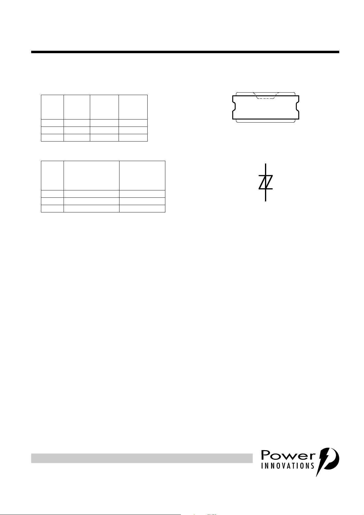
device symbol
T(A)
R(B)
CELL PACKAGE
(SIDE VIEW)
MD4XANA
●
Ion-Implanted Breakdown Region
Precise and Stable Voltage
Low Voltage Overshoot under Surge
2EL2, 2EL3, 2EL4
BIDIRECTIONAL THYRISTOR OVERVOLTAGE PROTECTORS
AUGUST 1998Copyright © 1998, Power Innovations Limited, UK
V
(BR)
DEVICE
2EL2 ±245 ±265 ±400
2EL3 ±200 ±265
2EL4 ±215 ±265
●
DEVICE
2EL2 ±125 ±100
2EL3 ±125 ±100
2EL4 ±125 ±100
●
●
MINIMUM
V
Rated for International Surge Wave Shapes
Gas Discharge Tube (GDT) Replacement
Planar Passivated Junctions in a Protected Cell Construction
MINIMUM
ITU-T K28
(10/700)
I
TSP
A
V
(BO)
V
V
(BO)
MAXIMUM
V
GR-974-CORE
(10/1000)
I
TSP
A
Low Off-State Current
Extended Service Life
●
Soldered Copper Electrodes
High Current Capability
Cell Construction Short Circuits Under Excessive Current Conditions
T
SD4XAA
R
Terminals T and R correspond to the
alternative line designators of A and B
description
PRODUCT INFORMATION
Information is current as of publication date. Products conform to specificat ions in accordance
with the terms of Power Innovations standard warranty. Production processing does not
necessarily include testing of all parameters.
Manufactured by TI using silicon designed and manufactured by Power Innovations, Bedford, UK.
These devices are primary protector components for semiconductor arrester assemblies intended to meet the
generic requir ements of Bellcor e GR-974-CORE (November 1994) or ITU-T Recom mendation K28 (03/93).
To conform to the specified environmental requirements, the 2ELx must be installed in a housing which
maintains a stable microclimate during these tests (e.g. FIGURE I.1/K28).
The protector consists of a symmetrical voltage-triggered bidirectional thyristor. Overvoltages are initially
clipped by breakdown clamping until the voltage rises to the breakover level, which causes the device to
crowbar into a low-voltage on state. This low-voltage on state causes the current resulting from the
overvoltage to be safely diverted through the device. The high crowbar holding cu rrent prevents d.c. latchup
as the diverted current subsides. This 2ELx range consists of three voltage variants to meet various
maximum system voltage levels. They are guaranteed to voltage limit and withstand the listed inter national
lightning surges in both polarities.
These monolithic protec tion devices are constructed usi ng two nickel plated copper electrodes sold ered to
each side of the sili con chip. This packaging approac h allows heat to be removed from both sides of the
silicon, resulting in the doubling of the devices thermal capacity, enabling a power line cross current capability
of 10 A rms for 1 second. O ne of the 2E Lx’s copper electrodes is spe cial ly shap ed to p romot e a pr ogressive
shor ting acti on (at 50/6 0 Hz currents greater than 60 A ). The asse mbly must hold the 2ELx in co mpression ,
so that the cell electrodes can be forced together during overstress testing. Under excessive power line cross
conditions the 2ELx will fail short circuit, providing maximum protection to the equipment.
1
Page 2

2EL2, 2EL3, 2EL4
BIDIRECTIONAL THYRISTOR OVERVOLTAGE PROTECTORS
AUGUST 1998
T
absolute maximum ratings,
Non-repetitive peak on-state pulse current (see Notes 1 and 2)
5/310 µs (ITU-T K28, 10/700 µs voltage wave shape) 2EL2
10/1000 µs (GR-974-CORE, 10/1000 µs voltage wave shape) 2EL2
Non-repetitive peak on-state current (see Note 1)
full sine wave, 50/60 Hz, 1 s 2EL2
Junction temperature T
Storage temperature range T
= 25°C (unless otherwise noted)
A
RATING SYMBOL VALUE UNIT
-20°C to 65°C
2EL3
2EL4
2EL3
2EL4
2EL3
2EL4
-20°C to 65°C
-20°C to 65°C
-20°C to 65°C
-20°C to 65°C
-20°C to 65°C
-40°C to 65°C
-20°C to 65°C
-40°C to 65°C
I
TSP
I
TSM
stg
125
125
125
100
100
100
10
10
10
J
-40 to +150 °C
-40 to +150 °C
A
A rms
NOTES: 1. The surge may be repeated after the device has returned to thermal equilibrium.
2. Mos t PTT’s quote an unloaded voltage waveform. In operation the 2ELx essentially shorts the generator output. The resulting
loaded current waveform is specified.
electrical characteristics for the T and R terminals, TA = 25°C (unless otherwise noted)
PARAMETER TEST CONDITIONS MIN TYP MAX UNIT
Breakdown Voltage I
V
(BR)
Breakover voltage dv/dt = ±0.2 V/s, R
V
(BO)
Impulse breakover
V
(BO)
voltage
Impulse reset
Off-state current
I
D
Off-state capacitance
C
off
= ±20 mA, (see Note 3) 2EL2 -40°C to 65°C ±245 V
(BR)
Ω
> 200
SOURCE
100 V/µs≤dv/dt≤±1000 V/µs,
di/dt≤10 A/µs
Sources are 52.5 V O.C., 260mA S.C. and
135 V O.C., 200 mA S.C.
on-state current 25 A, 10/1000 µs impulse
V
= ±50 V (see Note 4)
D
= ±200 V
V
D
f=1MHz, V
= 1 Vrms, VD= 0, 2EL2
d
2EL2
2EL3
2EL4
2EL2
2EL3
2EL4
2EL2
2EL3
2EL4
2EL2
2EL3
2EL4
2EL2
2EL3
2EL4
2EL3
2EL4
+15°C to 25°C
-40°C to 65°C
+15°C to 25°C
-20°C to 65°C
25°C
-20°C to 65°C
-20°C to 65°C
-20°C to 65°C
-20°C to 65°C
-20°C to 65°C
-20°C to 65°C
-40°C to 65°C
-20°C to 65°C
-40°C to 65°C
-40°C to 65°C
15°C to 25°C
0°C to 65°C
-40°C to 65°C
-20°C to 65°C
-40°C to 65°C
±265
±200
±215
±400
±265
±265
±400
±350
±350
20
20
20
±0.5
±0.5
±0.5
±10
±1
±10
150
150
150
V
V
ms
µA
pF
NOTES: 3. Meets Bellcore GR-974-CORE Issue 1, November 1994 - Rated Voltage Test (4.7)
4. This device is sensitive to light. Suggest that this parameter be measured in a dark environment
PRODUCT INFORMATION
2
Page 3

BIDIRECTIONAL THYRISTOR OVERVOLTAGE PROTECTORS
PARAMETER MEASUREMENT INFORMATION
2EL2, 2EL3, 2EL4
AUGUST 1998
-v
V
V
Quadrant III
Switching
Characteristic
Figure 1. VOLTAGE-CURRENT CHARACTERISTIC FOR T AND R TERMINALS
+i
I
TSP
I
TSM
(BR)
(BO)
V
D
I
(BR)
I
D
I
D
I
TSM
I
TSP
V
D
-i
ALL MEASUREMENTS ARE REFERENCED TO THE R TERMINAL
Quadrant I
Switching
Characteristic
V
(BO)
V
(BR)
I
(BR)
+v
PMXXAG
PRODUCT INFORMATION
3
Page 4

2EL2, 2EL3, 2EL4
BIDIRECTIONAL THYRISTOR OVERVOLTAGE PROTECTORS
AUGUST 1998
MECHANICAL DATA
cell package
BUTTON CELL 2ELx
2,31 (0.091)
2,11 (0.083)
1,65 (0.065)
2xø
1,27 (0.050)
0,508 (0.020)
MAX
0,178 (0.007)
MAX
Top Electrode
Sleeve
Bidirectional
Silicon Chip
Bottom Electrode
4,27 (0.168)
ø
3,76 (0.148)
ALL LINEAR DIMENSIONS IN MILLIMETERS AND PARENTHETICALLY IN INCHES
PRODUCT INFORMATION
4
MDXXAK
Page 5

2EL2, 2EL3, 2EL4
BIDIRECTIONAL THYRISTOR OVERVOLTAGE PROTECTORS
AUGUST 1998
IMPORTANT NOTICE
Power Innovations Limited (PI) reserves the right to make changes to its products or to discontinue any semiconductor product
or service without notice, and advises its customers to verify, before placing orders, that the information being relied on is
current.
PI warrants performance of its semiconductor products to the specifications applicable at the time of sale in accordance with
PI's standard w arra nty. Testing and other quality control tec hnique s are utilis ed to the extent PI dee ms nece ssary to supp ort this
warranty. Specific testing of all parameters of each dev ic e is not necessarily perf ormed, except those manda ted by gove rnment
requirements.
PI assumes no liability for applications assistance, customer product design, software performance, or infringement of patents
or services described herein. Nor is any license, either express or implied, granted under any patent right, copyright, design
right, or other inte llectual p roperty right of PI covering or relating to any combination, machine, or process in which such
semiconductor products or services might be or are used.
PI SEMICONDUCTOR PRODUCTS ARE NOT DESIGNED, INTENDED, AUTHORISED, OR WARRANTED TO BE SUITABLE
FOR USE IN LIFE-SUPPORT APPLICATIONS, DEVICES OR SYSTEMS.
Copyright © 1998, Power Innovations Limited
PRODUCT INFORMATION
5
 Loading...