

Datasheet 269-D-280-M-14xx-C, 269-D-280-M-14xx-B, 269-D-280-M-14xx-A, 269-D-280-D-14xx-C, 269-D-270-M-14xx-C Datasheet (AGERE)
...Page 1

269-Type 14xx nm DFB Pump Laser Module
Data Sheet
June 2001
The 269-type DFB pump laser module is designed as a
continuous-wave (CW) optical pump source for erbiu m-do ped
fiber amplifiers.
Features
■
Low relative intensity noise (RIN)
■
High-coupled rated output power up to 280 mW,
CW
■
Wide environmental range
■
Field-proven packaging technology
■
InGaAsP/InP high-power, strained multiple quantum-well (MQW), distributed-feedback (DFB) laser
chip design
■
Internal optical isolator (optional)
■
Internal thermoelectric cooler (TEC)
■
InGaAs PIN photodetector back-facet monitor
■
Single-mode and polarization-maintaining fiber pigtails
■
Compact, 14-pin butterfly package
■
Industry compatible package and pinout
Applications
■
Raman pump modules (RPM), copropagating and
counterpropagating
■
Erbium-doped fiber amplifiers (EDFA)
Description
The 269-type DFB pump laser module represen ts a
family of thermoelectrically cooled, high-power
lasers. These devices achieve stable wavelength
performance within the 1420 nm to 1510 nm range,
over the full operating temperature range. They are
designed as continuous-wave (CW) optical pump
sources for dense wavelength-division multiplexing
(DWDM) EDFA and Raman applications operating in
the C- and L-bands.
These new high-power DFB products represent a
breakthrough in 14xx nm pump laser technology by
integrating the beneficial characteristics of an external FBG laser design (such as stimulated Brillouin
scattering suppression) with the superior relativeintensity noise (RIN) performance of a DFB laser.
The combination of both characteristics is critical to
enable copropagating Raman pumping, which distributes gain over the first few kilometers of the transmission fiber. The typical RIN value Agere Systems’
DFB lasers is –158 dB/Hz, a major improvement over
comparable external FBG-stabilized lasers with a
typical RIN of –125 dB/Hz. Integrating wavelength
stabilization into the chip improves the stabilization
over operating temperature and thereby eliminates
the need for an external FBG .
The laser modules incorporate a high-power, quantum-well laser chip that achieves fiber powers up to
280 mW.
An integral thermoelectric cooler (TEC) stabilizes the
laser at room temperature and, combined with a hermetic environment, allows the device to achieve
high-power operation over the extended temperature
range of 0 °C to 75 °C. An internal InGaAs PIN photodiode, mounted behind the laser diode, functions
as the laser detector and monitors light emissions
from the rear facet of the laser.
The 269-type DFB module is offered in a 14-pin, hermetic butterfly package.
Page 2

Data Sheet
269-Type 14xx nm DFB Pump Laser Module June 2001
2
Agere Systems Inc.
Absolute Maximum Ratings
Stresses in excess of the absolute maximum ratings can cause permanent damage to the device. These are absolute stress ratings only. Functional operation of the device is not implied at these or any other conditions in excess
of those given in the operational sections of the data sheet. Exposure to absolute maximum ratings for extended
periods can adversely affect device reliability.
Handling Precautions
Electrostatic Discharge
CAUTION: This device is susceptible to damage as a result of electrostatic discharge (ESD). Take proper
precautions during both handling and testing. Follow guidelines such as
EIA
*
Standard
EIA
625.
Agere Systems Inc. employs a human-body model (HBM) for ESD-susceptibility testing and protection-design evaluation. ESD voltage thresholds are dependent on the critical parameters used to define the model. A standard
HBM (resistance = 1.5 kΩ, capacitance = 100 pF) is widely used and, therefore, can be used for comparison pur-
poses. The HBM ESD withstand voltage established for the 269-type laser pump module is ±500 V.
*
EIA
is a registered trademark of The Electronic Industries Association.
Parameter Symbol Min Max Unit
Operating Case Temperature Range T
C
075°C
Storage Case Temperature Range T
stg
–40 85 °C
Laser Forward Bias (TEC on):
P
O
= 120 mW—150 mW
P
O
= 160 mW—210 mW
P
O
= 220 mW—280 mW
I
F
—
—
—
1000
1500
1900
mA
mA
mA
Laser Reverse Voltage V
R
—2V
Photodiode Reverse Voltage V
RMON
—20V
TEC Current I
TEC
—2.2A
TEC Voltage V
TEC
—5.0V
Temperature Sensor Current I
TS
—5mA
Laser Diode Operating Chip Temperature T
LD
—40°C
Page 3
Data Sheet
June 2001 269-Type 14xx nm DFB Pump Laser Module
3
Agere Systems Inc.
Electrical/Optical Characteristics
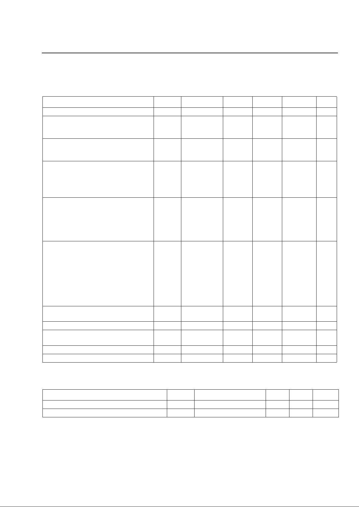
Table 1. Electrical/Optical Characteristics
(All performance parameters are specified for I
F, OP
, T
SET
= 25 °C,
T
CASE
~ 25 °C, unless otherwise specified.)
Parameter Symbol Conditions Min Typ Max Unit
Operating Optical Power P
O
— 120 — 280 mW
Wavelength:
Target Wavelength
Center Wavelength
λt
λ
C
—
0 °C—70 °C
1420
λt – 1.0
—
—
1510
λt + 1.0
nm
nm
RMS Spectral Width:
Single Mode
Multimode
∆λ P
O
—
—
1.0
0.2
5.0
0.3
MHz
nm
BOL Operating Laser Forward Current:
P
O
= 120 mW
P
O
= 130 mW
P
O
= 140 mW
P
O
= 150 mW
I
F, OP BOL
—
—
—
—
—
—
—
—
—
—
—
—
550
600
600
600
mA
mA
mA
mA
BOL Operating Laser Forward Current:
P
O
= 160 mW
P
O
= 170 mW
P
O
= 180 mW
P
O
= 190 mW
P
O
= 200 mW
I
F, OP BOL
—
—
—
—
—
—
—
—
—
—
—
—
—
—
—
650
700
700
750
800
mA
mA
mA
mA
mA
BOL Operating Laser Forward Current:
P
O
= 210 mW
P
O
= 220 mW
P
O
= 230 mW
P
O
= 240 mW
P
O
= 250 mW
P
O
= 260 mW
P
O
= 270 mW
P
O
= 280 mW
I
F, OP BOL
—
—
—
—
—
—
—
—
—
—
—
—
—
—
—
—
—
—
—
—
—
—
—
—
850
900
950
1000
1000
1100
1100
1100
mA
mA
mA
mA
mA
mA
mA
mA
EOL Operating Laser Forward Current I
F, OP EOL
———1.15 x
I
F, OP BOL
mA
EOL Laser Diode Forward Voltage V
R
I
F, OP
EOL — 2.3 3.0 V
Module Optical Isolation
(optional feature)
ISO EOL Over
T
CASE RANGE
30 — — dB
Polarization Extinction Ratio PER — 13 — — dB
Relative Intensity Noise RIN P
O
— –158 –150 dB/Hz
Table 2. Monitor Photodiode Characteristics
(All test parameters are specified for I
F, O P, TSET
= 25 °C,
T
CASE
~ 25 °C unless otherwise specified.)
Parameter Symbol Conditions Min Max Unit
Monitor Diode Current I
BF
— 200 2000 µA
Monitor Diode Dark Current
I
D
VR = –5 V, IF = 0 — 100 nA
Page 4

Data Sheet
269-Type 14xx nm DFB Pump Laser Module June 2001
4
Agere Systems Inc.
Electrical/Optical Characteristics
(continued)
Table 3. TEC and Thermistor Characteristics
(All performance parameters are specified for I
F, OP, TSET
= 25 °C,
unless otherwise specified.)
Parameter Symbol Conditions M in Max Unit
TEC Current:
P
O
= 120 mW
P
O
= 130 mW
P
O
= 140 mW
P
O
= 150 mW
I
TEC
T
SET
= 25 °C;
T
CASE
= 75 °C;
∆T = 50 °C, EOL
—
—
—
—
1.6
1.6
1.6
1.6
A
A
A
A
TEC Current:
P
O
= 160 mW
P
O
= 170 mW
P
O
= 180 mW
P
O
= 190 mW
P
O
= 200 mW
I
TEC
T
SET
= 25 °C;
T
CASE
= 70 °C;
∆T = 45 °C, EOL
—
—
—
—
—
1.7
1.7
1.7
1.7
1.7
A
A
A
A
A
TEC Current:
P
O
= 210 mW
P
O
= 220 mW
P
O
= 230 mW
P
O
= 240 mW
P
O
= 250 mW
P
O
= 260 mW
P
O
= 270 mW
P
O
= 280 mW
I
TEC
T
SET
= 25 °C;
T
CASE
= 65 °C;
∆T = 40 °C, EOL
—
—
—
—
—
—
—
—
2.0
2.0
2.0
2.0
2.0
2.0
2.0
2.0
A
A
A
A
A
A
A
A
TEC Voltage:
P
O
= 120 mW
P
O
= 130 mW
P
O
= 140 mW
P
O
= 150 mW
V
TEC
T
SET
= 25 °C;
T
CASE
= 75 °C;
∆T = 50 °C, EOL
—
—
—
—
3.5
3.5
3.5
3.5
V
V
V
V
TEC Voltage:
P
O
= 160 mW
P
O
= 170 mW
P
O
= 180 mW
P
O
= 190 mW
P
O
= 200 mW
V
TEC
T
SET
= 25 °C;
T
CASE
= 70 °C;
∆T = 45 °C, EOL
—
—
—
—
—
3.7
3.7
3.7
3.7
3.7
V
V
V
V
V
TEC Voltage:
P
O
= 210 mW
P
O
= 220 mW
P
O
= 230 mW
P
O
= 240 mW
P
O
= 250 mW
P
O
= 260 mW
P
O
= 270 mW
P
O
= 280 mW
V
TEC
T
SET
= 25 °C;
T
CASE
= 65 °C;
∆T = 40 °C, EOL
—
—
—
—
—
—
—
—
4.2
4.2
4.2
4.2
4.2
4.2
4.2
4.2
V
V
V
V
V
V
V
V
Thermistor Resistance
R
THERM
25 °C Laser Diode
Set Temperature
9.5 10.5 kΩ
Themistor B Constant B — 3700 4100 K
Page 5

Data Sheet
June 2001 269-Type 14xx nm DFB Pump Laser Module
5
Agere Systems Inc.
User Information
* A positive input into this pin cools the laser.
Fiber Characteristics
■
Length of fiber pigtail:
— 1.75 m ± 0.25 m
■
Standard fiber:
— Cladding OD: 125 µm ± 2 µm
— Acrylate buffer OD: 250 µm ± 15 µm
— Cut off wavelength: <1320 nm
■
Polarization-maintaining fiber:
— PANDA
— Cut off wavelength: <1400 nm
— Acrylate buffer: 400 µm
Table 4. Pin Information
Pin
Number
Connection
1 TE Cooler (+)*
2 Thermistor
3 Monitor Anode (–Bias)
4 Monitor Cathode (+Bias)
5 Thermistor
6 No Connect
7 No Connect
8 No Connect
9 No Connect
10 Laser Anode (+)
11 Laser Cathode (–)
12 No Connect
13 Package Ground
14 TEC Cooler (–)
Mounting and Connections
CAUTION: This device is susceptible to damage as
a result of electrostatic discharge.
Proper precautions should be taken
during both handling and testing.
The base of the laser module (see Outline Diagram)
should be maintained at or below 75 °C (maximum)
during operation. Interfaces between the laser module
base and heat sink must be clean, and the use of a
thermal filler may be necessary.
Mounting Instructions
The minimum fiber bend radius is 1.0 in.
To avoid degradation in performance, mount the mod-
ule on the board as follows:
1. Place the bottom flange of the module on a flat heat
sink at least 0.5 in. x 1.180 in. (12.7 mm x 30 mm)
in size. The surface finish of the heat sink should be
better than 32 µin. (0.8 µm), and the surface flatness must be better than 0.001 in. (25.4 µm). Using
thermal conductive grease is optional; however,
thermal performance may be improved if conductive
grease is applied between the bottom flange and
the heat sink.
2. Mount four #2-56 screws with Fillister heads
(M2-3 mm) at the four screw hole locations (see
Outline Diagram). The Fillister head diameter must
not exceed 0.140 in. (3.55 mm). Do not apply more
than 1 in./lb. of torque to the screws.
Figure 1. Circuit Schematic
1-675 (F).i
7654321
8 9 10 11 12 13
14
TH 10 k
Ω
TEC
ISOLATOR
–
+
+
–
(OPTIONAL)
Page 6

Data Sheet
269-Type 14xx nm DFB Pump Laser Module June 2001
6
Agere Systems Inc.
Outline Diagram
Dimensions are in inches and (millimeters).
1-1065 (F)a
0.10 (0.25)
0.035
(0.91)
0.078
(1.98)
0.213 (5.40) TYP.
0.350
(8.89)
0.500
(12.70)
0.598
(15.19)
MAX.
1.025
(26.04)
0.020
(0.51)
0.100 (2.54) TYP.
TYP.
PIN 1
0.105 (2.667) DIA.
TYP. (4) PLACES
PIN 14
0.030 (0.76)
0.700
(17.78)
0.347
(8.8)
0.820
(20.83)
0.180
(4.57)
0.175
(4.45)
0.215
(5.46)
1.180
(29.97)
0.078
(1.99)
0.178
(4.52)
0.215 ± 0.10
(5.46 ± 2.54)
0.363
(9.23)
0.334 ± 0.005
(8.49 ± 0.005)
Page 7

Data Sheet
June 2001 269-Type 14xx nm DFB Pump Laser Module
7
Agere Systems Inc.
Laser Safety Information
Class IIIb Laser Product
FDA/CDRH Class IIIb laser product. All versions are Class IIIb laser products per CDRH, 21 CFR 1040 Laser
Safety requirements. All versions are Class IIIb laser products per
IEC
* 60825-1:1993. The device has been
classified with the FDA under accession number 8720010.
This product complies with 21 CFR 1040.10 and 1040.11.
8.8 µm/125 µm single-mode fiber pigtail (see Fiber Characteristics, page 5).
Wavelength = 1.40 µm—1.52 µm.
Maximum power = 400 mW.
Because of size constraints, laser safety labeling (including an FDA Class IIIb label) is not affixed to the module but
attached to the outside of the shipping carton.
Product is not shipped with power supply.
Caution: Use of controls, adjustments, and procedures other than those specified herein may result in
hazardous laser radiation exposure.
*
IEC
is a registered trademark of The International Electrotechnical Commission.
DANGER
INVISIBLE LASER RADIATION
IS EMITTED FROM THE END
OF FIBER OR CONNECTOR
Avoid direct exposure to beam
Do not view beam directly with
optical instruments
INVISIBLE LASER RADIATION EMITTED FROM END OF FIBER OR CONNECTOR
Avoid exposure to beam
Class 3B Laser Product IEC-60825M 1993 Max. Output: 400 mW Wavelength: 1.40 µm—1.52
µm
Page 8

Data Sheet
269-Type 14xx nm DFB Pump Laser Module June 2001
For additional information, contact your Agere Systems Account Manager or the following:
INTERNET:
http://www.agere.com
E-MAIL:
docmaster@micro.lucent.com
N. AMERICA:Agere Systems Inc., 555 Union Boulevard, Room 30L-15P-BA, Alle ntown, PA 18109-3286
1-800-372-2447
, FAX 610-712-4106 (In CANADA:
1-800-553-2448
, FAX 610-712-4106)
ASIA PACIFIC:Agere Systems Singapore Pte. Ltd., 77 Science Park Drive, #03-18 Cintech III, Singapore 118 256
Tel. (65) 778 8833
, FAX (65) 777 7495
CHINA: Agere Systems (Shanghai) Co., Ltd ., 33/F Jin Mao Tower, 88 Century Boulevard Pudong, Shang ha i 200 12 1 PRC
Tel. (86) 21 50471212
, FAX (86) 21 50472266
JAPAN: Agere Systems Japan Ltd., 7-18, Higashi-Gotanda 2-chome, Shinagawa-ku, Tokyo 141, Japan
Tel. (81) 3 5421 1600
, FAX (81) 3 5421 1700
EUROPE: Data Requests: DATALINE:
Tel. (44) 7000 582 368
, FAX (44) 1189 328 148
Technical Inquiries: OPTOELECTRONICS MARKETING:
(44) 1344 865 900
(Ascot UK)
Agere Systems Inc. reserves the right to make changes to the product(s) or information contained herein without notice. No liability is assumed as a result of their use or application.
Copyright © 2001 Agere Systems Inc.
All Rights Reserved
June 2001
DS01-237OPTO
Ordering Information
Device Code Information
ORDER CODE: X
X
269 – – XX – X – XXXX –
BASIC PART NUMBER
FIBER
A = NONISOLATED, SMF
CONNECTOR OPTIONS
A = NO CONNECTOR
B = NONISOLATED, PMF
B = SC/APC
C = FC/APC
WAVELENGTH
XXXX nm
C = ISOLATED, SMF
D = ISOLATED, PMF
OPERATING POWER
XX0 mW
OPERATING MODE
D = DFB, SINGLE MODE
M = DFB, MULTIMODE
 Loading...