

Page 1
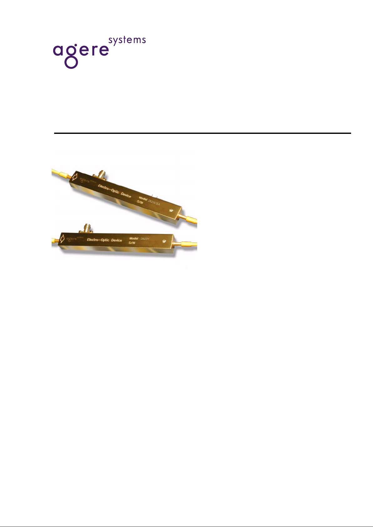
10 Gbits/s Lithium Niobate Electro-Optic Modulator
Data Sheet
May 2001
The Lithium Niobate Modulators include three single-drive
modulators (2623N, 2623Y, 2623CS) and a single-drive modulator with an integrated attenuator (2623CSA). All devices are
capable of modulation rates up to 10 Gbits/s.
Features
■
Ti-diffusion process
■
Single-drive technology
■
C- and L-band models
■
Slim, hermetic package
■
Bandwidths up to 10 GHz
■
Operational over a temperature range of 0 °C to
70 °C
■
43 Ω design for minimal electrical reflections
■
Angled interfaces for minimal optical reflections
■
Integrated optical attenuator available on
10 Gbits/s modulator (2623CSA)
■
Tested to
Telcordia Te chnologies
* 468
Benefits
■
Excellent long-term bias stability
■
Internal polarizer
■
Low modulation voltages
Applications
■
Digital high-speed telecommunications:
— SONET: OC-1 through OC-192
— SDH: STM-16, STM-64
— Undersea communications
■
Internet data communications
■
SONET/SDH test equipment
*
Telcordia Technologies
is a trademark of Telcordia Technologies,
Inc.
Page 2

Data Sheet
10 Gbits/s Lithium Niobate Electro-Optic Modulator May 2001
22 Agere Systems Inc.
Description
The 10 Gbits/s Electro-Optic Modulator is designed for
long-wavelength, single-mode external amplitude modulation applications. It uses an integrated MachZehnder configuration to convert single polarization
CW light from a semiconductor (DFB) laser into a timevarying optical output signal. Agere Systems Inc. also
offers a 10 mW CW laser with polarization-maintaining
fiber (D2525P) to use as a source for the modulator.
The Ti-diffusion process is a standard feature on all
modulator devices. The 2623N, 2623Y, and 2623CS
are single-drive, 10 Gbits/s modulators; the 2623CSA
is a single-drive, 10 Gbits/s modulator with an attenuating section. Variable attenuation to >19 dB is achieved
through a dc bias voltage.
The package is hermetic to protect the LiNbO
3
die from
the environment. Novel processing techniques now
make it possible to achieve 20-year operation with little
drift in the dc bias point. The modulator is tested to, and
meets the intent of TR-NWT-00468.
Other standard features include PANDA-type polarization-maintaining fiber (PMF) for the optical input (all
codes) and output (2623N, 2623Y, and 2623C) fiber
with FC-type connectors that are keyed to the axis of
polarization. Custom designs are available.
Absolute Maximum Ratings
Stresses in excess of the absolute maximum ratings can cause permanent damage to the device. These are absolute stress ratings only. Functional operation of the device is not implied at these or any other conditions in excess
of those given in the operational sections of the data sheet. Exposure to absolute maximum ratings for extended
periods can adversely affect device reliability.
Parameter Symbol Min Max Unit
Storage Temperature T
stg
–40 85 °C
Optical Input Power @ 1.5 µm
P
IN
—
30 mW
RF Voltage (peak to peak) V
RF
—
10 V
dc Voltage (RF input) V
dcRF
–20 20 V
dc Voltage (Attenuator input) V
dcATT
–25 25 V
Operating Temperature T
OP
070°C
Page 3
Data Sheet
May 2001 10 Gbits/s Lithium Niobate Electro-Optic Modulator
3
Agere Systems Inc.
Optical/Electrical Characteristics
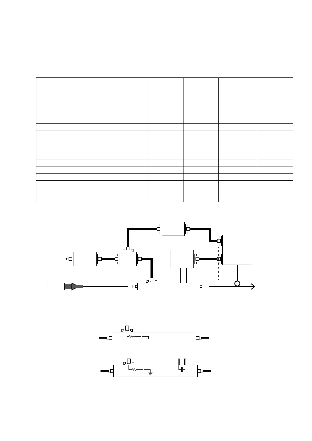
* Bandwidth stated is electrical-optical-electrical as determined by the ratio of the received RF electrical power (at a photodiode) relative to the
RF electrical power used to drive the modulator. This response is referenced to the value at 130 MHz.
Note: Circuitry in dotted lines is used only with the 2623CSA.
Figure 1. Recommended Operating Circuit Diagram
Figure 2. Equivalent Circuit Diagram
Table 1. Optical/Electrical Characteristics
Parameter Min Typ Max Unit
Operating Wavelength:
C-band
L-band
1525
1565
—
—
1565
1620
nm
nm
Insertion Loss:
2623N, 2623Y, 2623CS
2623CSA
3
3.5
3.7
4.5
5.5
6.5
dB
dB
Extinction Ratio @ dc 20 27 — dB
Extinction Ratio @ RF — 13 — dB
S11 Optical Return Loss — — –35 dB
Bandwidth* 8 10 — GHz
Drive Voltage (Vπ) @ dc 2.8 3.1 4.0 V
Drive Voltage (Vπ) @ 1 GHz 3.5 4.1 5.0 V
Attenuation Voltage @ –19 dB 15 19 22 V
Electrode Impedance — 43 — Ω
S11 Electrical Return Loss (0.13 GHz—5 GHz) — –15 –13 dB
S11 Electrical Return Loss (5 GHz—10 GHz) – –14 –12 dB
S11 Electrical Return Loss (10 GHz—18 GHz) — –8 –6 dB
MODULATOR
DRIVER
BIAS
TEE
dc BIAS
CONTROLLER
PHOTODETECTOR/
PREAMP
dc
ATTENUATION
CONTROLLER
HIGH-
SPEED
DATA
INPUT
PMF
CW-LASER 2623N, 2623Y, 2623CS, 2623CSA
SPLITTER
SEE NOTE.
2623N, 2623Y, 2623CS
43
Ω
0.2 µF
43
Ω
0.2 µF
–10 pF
2623CSA
1-1063 (F)
1-1062 (F)
Page 4
Data Sheet
10 Gbits/s Lithium Niobate Electro-Optic Modulator May 2001
4
Agere Systems Inc.
Optical/Electrical Characteristics
(continued)
Electrical Signal Input
Electrical signal input is made through SMA coaxial connectors. The standard device includes an internal termination network. Care must be taken not to exceed the recommended 8 in./lb. of torque when making connections to
these inputs. High-frequency coaxial cable is recommended.
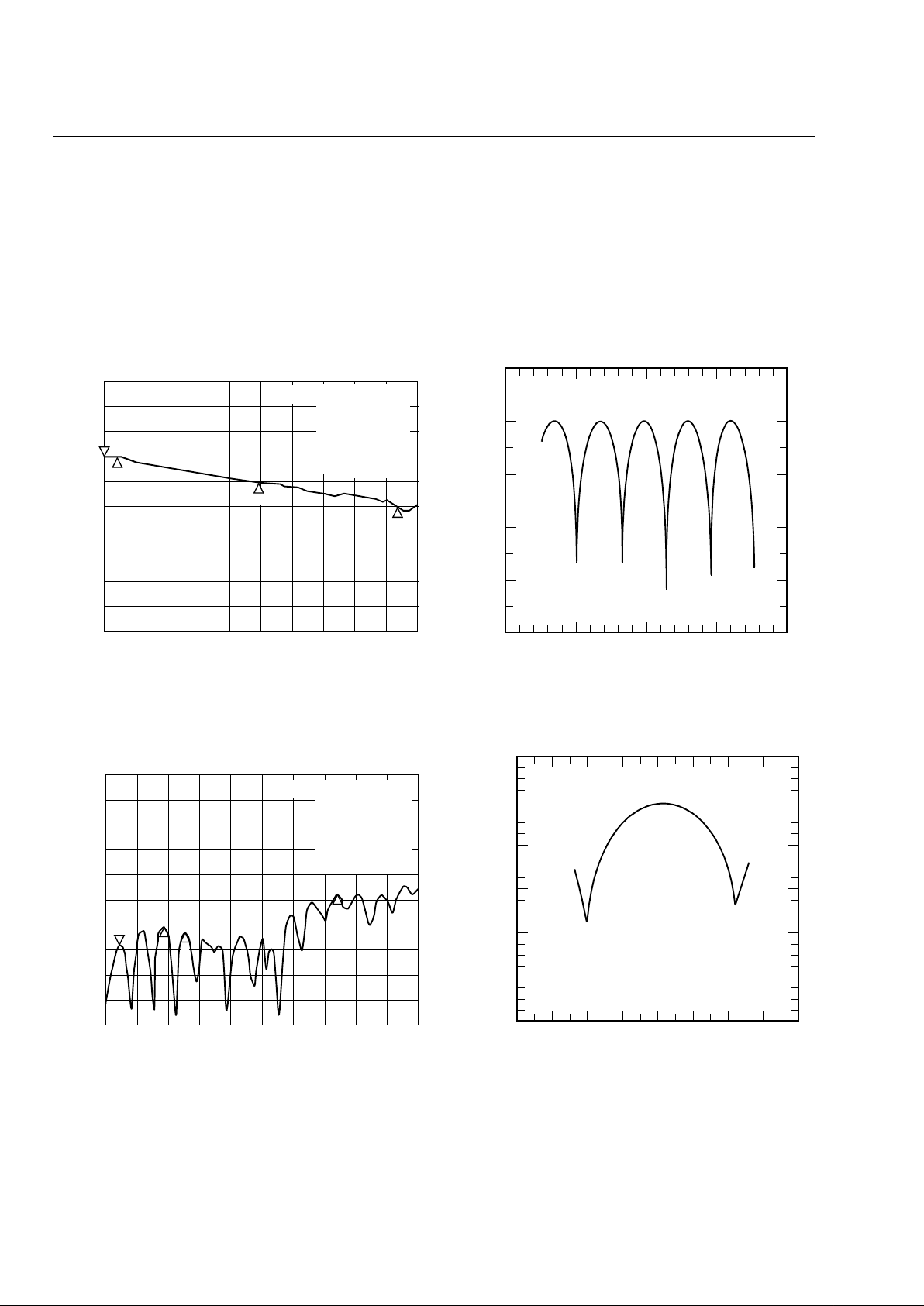
Characteristic Curves
Figure 3. Magnitude of Electro-Optic Response,
0.130 GHz—20 GHz.
Figure 4. S11, 0.130 GHz—20 GHz
Figure 5. Output Power vs. Bias Voltage
.
Figure 6. Optical Power vs. Attenuator Bias Voltage
dBe
COR
AVG
START .130 000 000 GHz STOP 20.000 000 000 GHz
LOG MAG3 dB/ REF –55.48 dB 1: –55.846 dBE/OCH1
W/A
4
HID
FREQUENCY
SMA
POWER (3dB/div)
1
2
4
3
1. 130 000 000 GHz
4. –61.766 dB
18.76 48 GHz
2. –55.476 dB
0.9248 GHz
3. –58.476 dB
9.9690 GHz
dBe
COR
START .130 000 000 GHz STOP 20.000 000 000 GH
z
LOG MAG 5 dB/ REF 0 dB 1: –18.896 dBS11CH1
HID
FREQUENCY
POWER (3 dB/div)
1
2
4
3
1. 924 000 000 GHz
4. –8.7734 dB
14.7344 GHz
2. –15.278 dB
3.7006 GHz
3. –16.27 dB
5.0975 GHz
0
–10
–20
–30
–40
–50
–20 –10 0 10 20
MODULATOR dc BIAS VOLTAGE (V )
OPTICAL POWER OUT (dB)
1-1060(F)
1-898 (C)
0
–10
–20
–30
–40
–50
–40 –20 0 20 40
ATTENUATOR BIAS VOLTAG E (V)
OPTICAL POWER (dB)
–60
–30 –10 10 30
START = –23.98 V STOP = 25.58 V
1-1061(F)
1-1058(F)
1-1059(F)
Page 5
Data Sheet
May 2001 10 Gbits/s Lithium Niobate Electro-Optic Modulator
5
Agere Systems Inc..
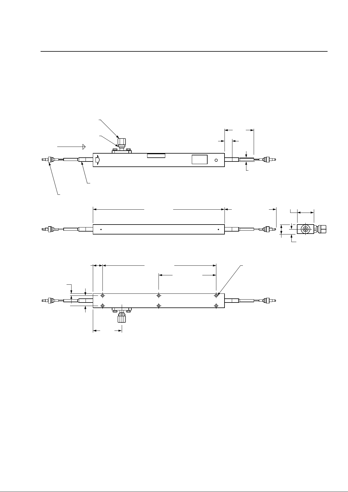
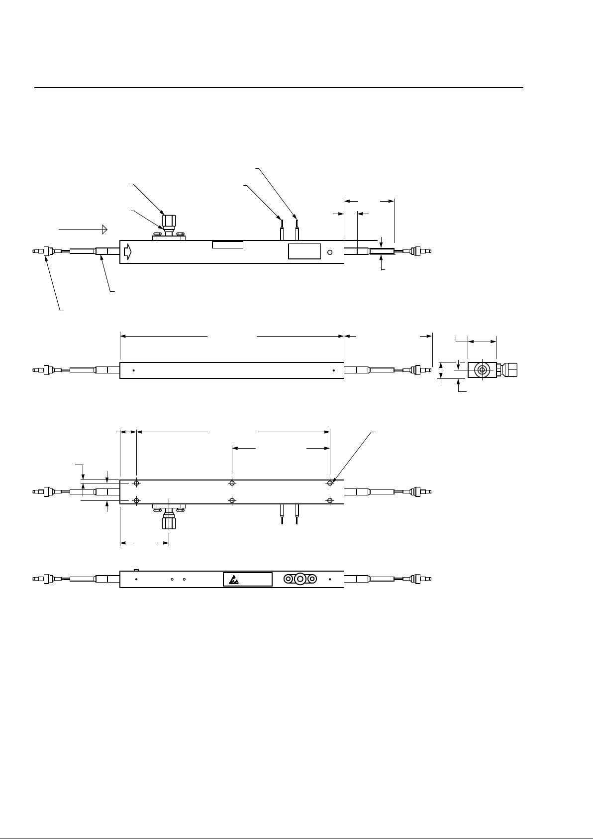
Outline Diagrams
Dimensions are in inches and (millimeters).
2623N, 2623Y, 2623CS Lithium Niobate Modulators
SMA SHORTING CAP
FIELD-REPLACEABLE
SMA CONNECTOR
BEND LIMITER
2 PLACES
FC/PC CONNECTOR OPTIONAL
2 PLACES
Agere Electro-Optic Modulator
Model
S/N
A06686 98
2623N
XXXX
0.20 (5.1)
1.20
(30.5)
0.14 (3.6)
1.5 METER
MAXIMUM
LOOSE-TUBE
JACKETED FIBER
2 PLACES
2623N S/N XXXX A0668698 014097001
0.32 (8.1)
0.43
#4-40 UNC 2B
0.12 (3.05) DEEP MIN,
6 PLACES
4.64 (117.9)
0.60 (15.2)
0.39
(9.8)
0.20
(5.11)
1.53
(38.9)
4.00 (101.6)
2.00 (50.8)
0.09 (2.2)
(10.8)
INPUT
1-1064(F)a
Page 6
Data Sheet
10 Gbits/s Lithium Niobate Electro-Optic Modulator May 2001
6
Agere Systems Inc.
Outline Diagrams
(continued)
2623CSA Lithium Niobate Modulator
1-1064F.c
SMA SHORTING CAP
FIELD-REPLACEABLE
SMA CONNECTOR
BEND LIMITER
2 PLACES
FC/PC CONNECTOR OPTIONAL
2 PLACES
Agere Electro-Optic Modulator
Model
S/N
A06686 98
2623CSA
XXXX
0.20 (5.1)
1.20
(30.5)
0.14 (3.6)
1.5 METER
MAXIMUM
LOOSE-TUBE
JACKETED FIBER
2 PLACES
2623CSA S/N XXXX A0668698 014097001
0.32 (8.1)
0.43
#4-40 UNC 2B
0.12 (3.05) DEEP MIN,
6 PLACES
4.64 (117.9)
0.60 (15.2)
0.39
(9.8)
0.20
(5.11)
1.53
(38.9)
4.00 (101.6)
2.00 (50.8)
0.09 (2.2)
(10.8)
INPUT
ATTENTION
ELECTROSTATIC
SENSITIVE
DEVICES
ATTENUATOR PIN # 2
ATTENUATOR PIN # 1
Page 7

Data Sheet
May 2001 10 Gbits/s Lithium Niobate Electro-Optic Modulator
7
Agere Systems Inc..
Package Information
Designed to NEBS (inside plant) standards, the hermetic package design incorporates a laser-sealed lid and soldered fibers. The minimum bend radius for the fiber is 1.5 in. To prevent warping, use only the two center screws to
mount the device.
Ordering Information
Table 2. Package Information
Description Type
Input Optical Fiber (all codes) PANDA-type PMF
Output Optical Fiber:
2623N, 2623Y, 2623CS
2623CSA
PANDA-type PMF
Standard Single-mode
Fiber Connector FC
Fiber Length 1.5 m max
RF Connector SMA
Package Dimensions See Outline Drawings, page 5, 6.
Table 3. Device Information
Part Number Minimum
Bandwidth
(GHz)
Attenuator C-Band L-Band Comcode
2623N 8 No Yes Yes 1077393100
2623Y 9 No Yes Yes 108864604
2623CS 10 No Yes Yes 107862823
2623CSA 8 Yes Yes Yes 108433954
Page 8

Data Sheet
10 Gbits/s Lithium Niobate Electro-Optic Modulator May 2001
For additional information, contact your Agere Systems Account Ma nager or the following:
INTERNET:
http://www.agere.com
E-MAIL:
N. AMERICA: Agere Systems Inc., 555 Union Boulevard, Room 30L-15P-BA, Allentown, PA 18109-3286
1-800-372-2447
, FAX 610-712-4106 (In CANADA:
1-800-553-2448
, FAX 610-712-4106)
ASIA PACIFIC: Agere Systems Singapore Pte. Ltd., 77 Science Park Drive, #03-18 Cintech III, Singapore 118256
Tel. (65) 778 8833
, FAX (65) 777 7495
CHINA: Agere Systems (Shanghai) Co., Ltd., 33/F Jin Mao Tower, 88 Century Boulevard Pudong, Shanghai 200121 PRC
Tel. (86) 21 50471212
, FAX (86) 21 50472266
JAPAN: Agere Systems Japan Ltd., 7-18, Higashi-Gotanda 2-chome, Shinagawa-ku, Tokyo 141, Japan
Tel. (81) 3 5421 1600
, FAX (81) 3 5421 1700
EUROPE: Data Requests: DATALINE:
Tel. (44) 7000 582 368
, FAX (44) 1189 328 148
Technical Inquiries:OPTOELECTRONICS MARKETING:
(44) 1344 865 900
(Ascot UK)
Agere Systems Inc. reserves the right to make changes to the product(s) or information contained herein without notice. No liability is assumed as a result of their use or application.
Copyright © 2001 Agere Systems Inc.
All Rights Reserved
May 2001
DS00-331OPTO-2 (Replaces DS00-331OPTO-1)
 Loading...