

Page 1
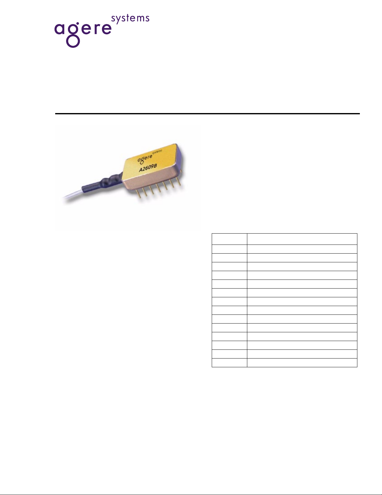
2609B Broadband Photodiode Module
Description
The 2609B is a packaged impedance-matched photodiode module with internal gain designed for use in
optical broadband receivers in fiber-optic networks.
The patented impedance-match technology results in
improved gain-bandwidth product compared to external circuits due to better control of parasitics between
the photodiode and the impedance-matching circuit.
Data Sheet
August 2000
Features
■
Flat response to ±0.5 dB
■
Frequency response up to 860 MHz
■
High responsivity:
—>0.85 A/W at 1310 nm
—0.95 A/W at 1550 nm
■
Internal current gain, 6 dB (typ.)
■
75 Ω impedance-matched
Applications
■
Broadband CATV receivers
Pin Information
Table 1. Pin Descriptions
Pin No. Description
1 Ground
2 Ground
3 Ground
4 Ground
5 Ground
6 Ground
7Open
8Open
9RF Out
10 Ground
11 Bias
12 Ground
13 Open
14 Ground
Page 2
Data Sheet
2609B Broadband Photodiode Module August 2000
Absolute Maximum Ratings
Stresses in excess of the absolute maximum ratings can cause permanent damage to the device. These are absolute stress ratings only. Functional operation of the device is not implied at these or any other conditions in excess
of those given in the operational sections of the data sheet. Exposure to absolute maximum ratings for extended
periods can adversely affect device reliability.
Parameter Symbol Min Max Unit
Operating Case Temperature Range T
C
–40 85 °C
Storage Temperature Range Tstg –40 85 °C
Optical Input Power P
Bias Voltage V
Forward Current I
IN
PD
F
—2mW
—20V
—10mA
Characteristics
Note: These product specifications describe warranted performance. Typical values provide expected levels of per-
formance, but are not guaranteed.
Table 2. Electrical/Optical Characteristics
Parameter Symbol Min Typ Max Unit
Optical Wavelength
λ 1310—1550 ± 30 — —nm
Range
Responsivity — —
—
Optical Return Loss
1
RL — >45 — dB
>0.85 at 1310 nm,
>0.95 at 1550 nm
—
—
mA/mW
mA/mW
Bias Voltage — — 15 (nominal) — V
Dark Current I
1. Without connector
.
D
— 200 at 20 °C—nA
Table 3. RF Characteristics
Parameter Symbol Min Typ Max Unit
Frequency Range F 40 — 860 MHz
Gain
1
G—>5—dB
Frequency Response — — <± 0.5 — dB
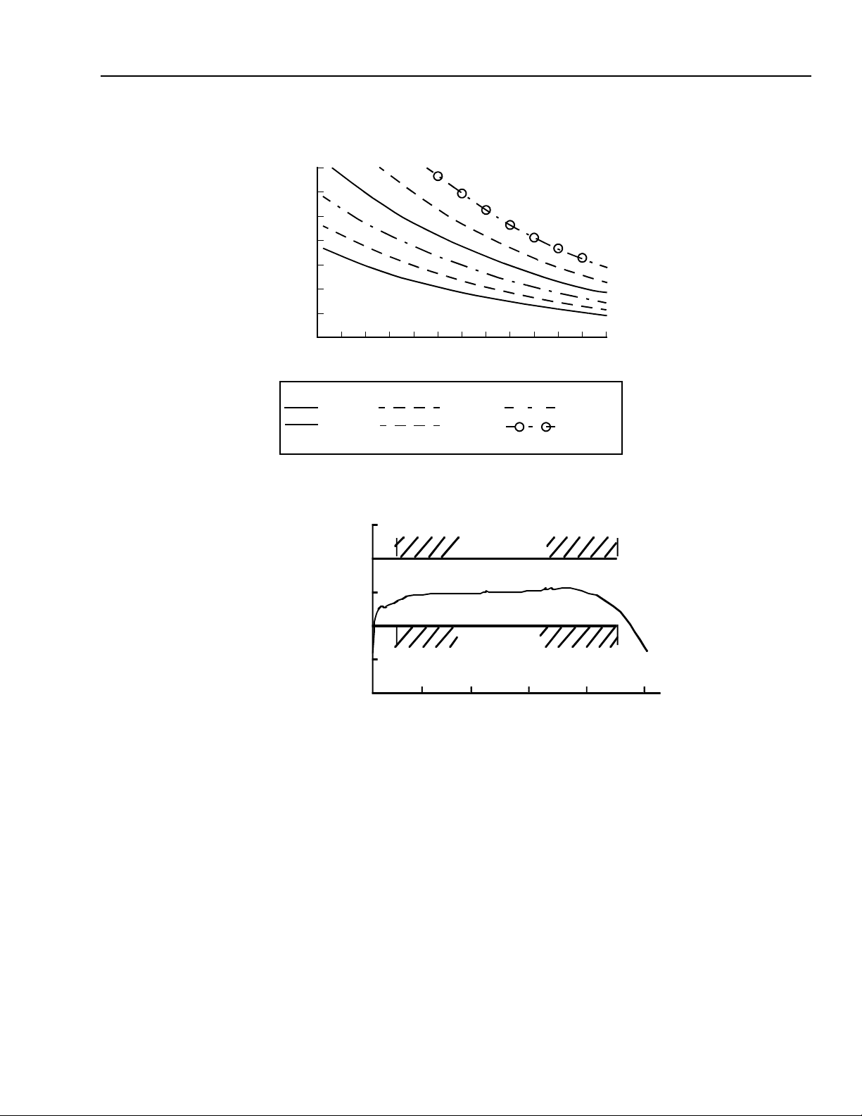
Receiver Noise — See Figure 1.
Distortion Products
Second Order
Third Order
1. Current gain of internal transformer circuit.
2. Two laser test. Each laser has 40% modulation index. Total received optical power is 0 dBm. Distortion products measured at 80 MHz,
450 MHz, 600 MHz, and 850 MHz.
2
CSO
CTB
—
—
<–70
<–80
—
—
dBc
dBc
2
Agere Systems Inc.
Page 3
Data Sheet
August 2000 2609B Broadband Photodiode Module
Characteristics Curves
14
)
1/2
RECEIVER NOISE (pA/Hz
KEY
X
12
10
8
6
4
2
0
0123456789101112
NF = 0 dB
NF = 6 dB
XX
X
X
X
X
X
X
XX
X
X
NF = 2 dB
NF = 8 dB
X
MATCHING GAIN (dB)
X
X
X
X
X
X
X
X
NF = 4 dB
NF = 10 dB
Figure 1. Receiver Noise
1.0
0.5
SPE C LIMIT
X
X
X
X
1-1182 (F).a
0
– 0 .5
– 1 .0
RELATI VE RESPONSE (dB)
– 2 .0
0 200 1000
SPE C LIMIT
40 0 60 0 80 0
FREQUE NCY (MHz)
1-1184 (F).a
Figure 2. Typical Frequency Response Measured into a 75 Ω Load, VSWR <1.5
Agere Systems Inc.
3
Page 4

Data Sheet
2609B Broadband Photodiode Module August 2000
Outline Diagram
Dimensions are in inches and (millimeters).
0.230
(5.842)
0.196
(4.978)
1-1183 (F).a
0.500
(12.7)
.100 TYP
0.300
(7.62)
0.800
(20.32)
0.600
(15.24)
PIN 14
PIN 1
0.018
(0.457)
0.118
(2.997)
Ordering Information
Table 4. Ordering Information
Device Code Description Connector Pigtail Comcode
2609B Broadband Photodiode Module None Single mode,
* Other options available. For additional ordering information, please contact an account manager at OPTO West, Agere Systems Inc. , 1-800-
362-3891 (for sales staff, please press option 2).
*
108867375
9 µm/125 µm
For additional information, contact your Agere Systems Account Ma na ger or the following:
INTERNET:
E-MAIL:
N. AMERICA: Agere Systems Inc., 555 Union Boulevard, Room 30L-15P-BA, Allentown, PA 18109-3286
ASIA PACIFIC: Agere Systems Singapore Pte. Ltd., 77 Science Park Drive, #03-18 Cintech III, Singapore 118256
CHINA: Agere Systems (Shanghai) Co., Ltd., 33/F Jin Mao Tower, 88 Century Boulevard Pudong, Shanghai 200121 PRC
JAPAN: Agere Systems Japan Ltd., 7-18, Higashi-Gotanda 2-chome, Shinagawa-ku, Tokyo 141, Japan
EUROPE: Data Requests: DATALINE:
Agere Systems Inc. reserves the right to make changes to the product(s) or information contained herein without notice. No liability is assumed as a result of their use or application.
Copyright © 2001 Agere Systems Inc.
All Rights Reserved
August 2000
DS00-294OPTO
http://www.agere.com
[email protected]
1-800-372-2447
Tel. (65) 778 8833
Tel. (86) 21 50471212
Tel. (81) 3 5421 1600
Technic al Inquiries: OPTOELECTRONICS MARKETING:
, FAX 610-712-4106 (In CANADA:
, FAX (65) 777 7495
, FAX (86) 21 50472266
, FAX (81) 3 5421 1700
Tel. (44) 7000 582 368
1-800-553-2448
, FAX (44) 1189 328 148
, FAX 610-712-4106)
(44) 1344 865 900
(Ascot UK)
 Loading...