

Page 1
24LC16
1
1
8
8
FORWARD
CMOS I2C 2-WIRE BUS
16K ELECTRICALLY ERASABLE PROGRAMMABLE ROM
2K X 8 BIT EEPROM
FEATURES :
Extended Power Supply Voltage
Single Vcc for Read and Programming
(Vcc = 2.7 V to 5.5 V)
Low Power (Isb = 2??a @ 5.5 V)
I2C Bus, 2-Wire Serial Interface
Support Byte Write and Page Write (16 Bytes)
Automatic Page write Operation (maximum 10 ms)
Hardware Data Protection by Write Protect Pin
High Reliability CMOS Technology with EEPROM Cell
Internal Control Timer
Internal Data Latches for 16 Bytes
Endurance : 1,000,000 Cycles
Data Retention : 100 Years
PIN DESCRIPTION
NC
NC
NC
GND GND
2
7
3
6
4 5
VCC WP
SCL
SDA
8 pin SOIC
NC
NC
NC
2
3
4 5
8 pin PDIP
7
6
DESCRIPTION:
The IC 24LC16 is a serial 16K EEPROM fabricated
with 's proprietary, high reliability, high performance
CMOS technology. It's 16K of memory is organized as 2,048
x 8 bits. The memory is configured as 128 pages with each
page containing 16 bytes. This device offers significant advantages in low power and low voltage applications.
The IC 24LC16 uses the I2C addressing protocol and
2-wire serial interface which includes a bidirectional serial
data bus synchronized by a clock. It offers a flexible byte
write and a faster 16-byte page write. The data in the upper
half of memory can be protected by a write protect pin.
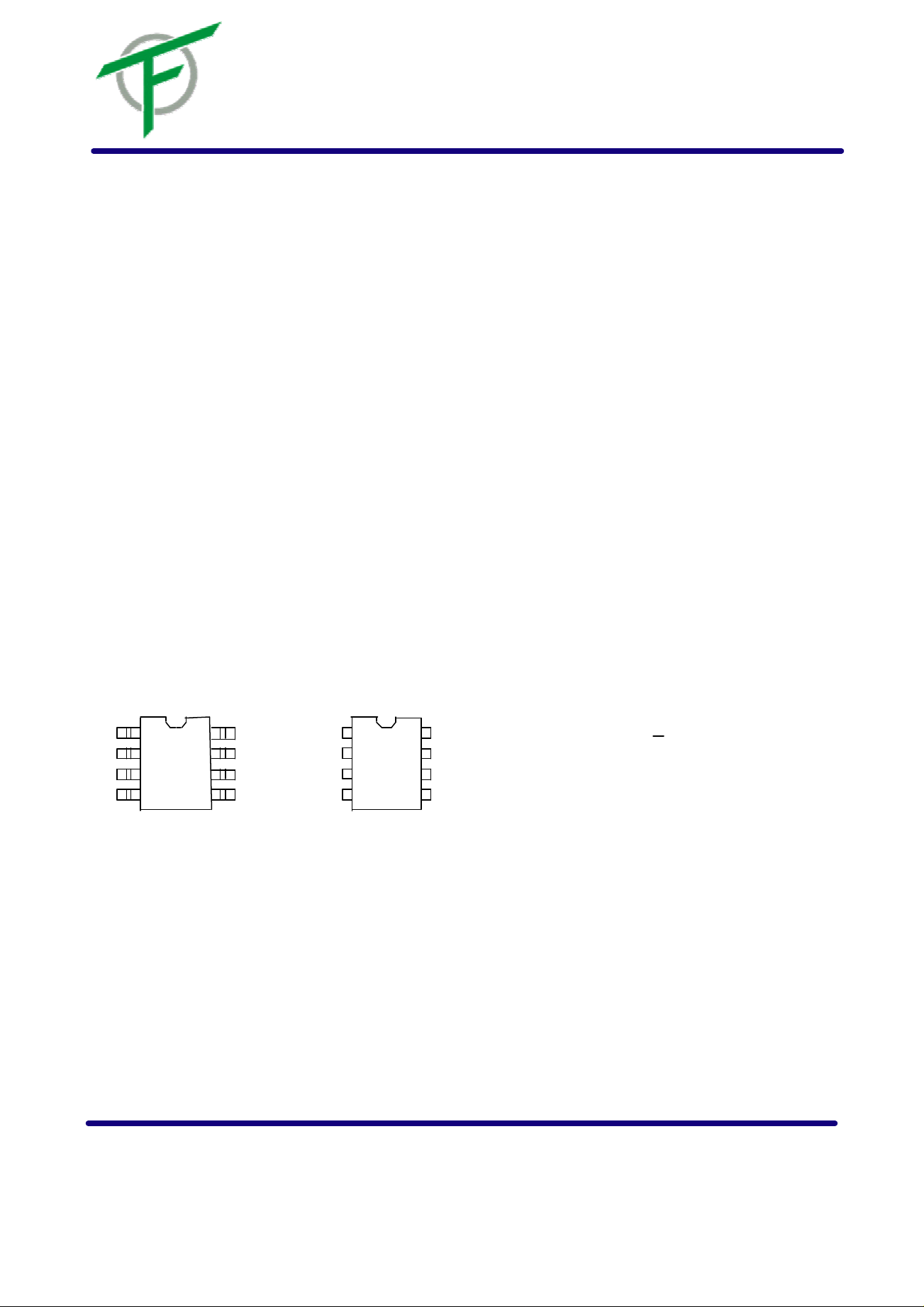
The IC 24LC16 is assembled in either a 8-pin PDIP or
8-pin SOIC package. Pin #1, #2, and #3 are not connected
(NC). Pin #4 is the ground (Vss). Pin #5 is the serial data
(SDA) pin used for bidirectional transfer of data. Pin #6 is
the serial clock (SCL) input pin. Pin #7 is the write protect
(WP) input pin, and Pin #8 is the power supply (Vcc) pin.
All data is serially transmitted in bytes (8 bits) on the SDA
bus. To access the IC 24LC16 (slave) for a read or
write operation, the controller (master) issues a start condition by pulling SDA from high to low while SCL is high. The
master then issues the device address byte which consists
VCC WP
of 1010 (B10) (B9) (B8) (R/W). The most significant bits
SCL
(1010) are a device type code signifying an EEPROM de-
SDA
vice. The B[10:8] bits are the 3 most significant bits of the
memory address. The read/write bit determines whether to
do a read or write operation. After each byte is transmitted,
the receiver has to provide an acknowledge by pulling the
SDA bus low on the ninth clock cycle. The acknowledge is a
handshake signal to the transmitter indicating a successful
data transmission.
PIN DESCRIPTION
WRITE PROTECT (WP) SERIAL DATA (SDA) SERIAL CLOCK (SCL)
When the write protect input is connected to Vcc,
the upper half of memory (400-7FFH) is protected
against write operations. For normal write opera tion, the write protect pin should be grounded.
When this pin is left unconnected, WP is interpreted as zero.
SDA is a bidirectional pin used to transfer data
in and out of the IC 24LC16. The pin is an
open-drain output. A pullup resistor must be connected from SDA to Vcc.
The SCL input synchronizes the data on the SDA
bus. It is used in conjunction with SDA to define
the start and stop conditions. It is also used in
conjunction with SDA to transfer data to and from
the IC 24LC16.
深圳市科威創新元器件有限公司 電話:0755-83573495/82975811 傳真:0755-83894721 1
Page 2
24LC16
DESCRIPTION (Continued):
For a write operation, the master issues a start condition, a
device address byte, a memory address byte, and then up to
16 data bytes. The IC 24LC16 acknowledges after each
byte transmission. To terminate the transmission, the master
issues a stop condition by pulling SDA from low to high while
SCL is high.
DEVICE OPERATION:
For a read operation, the master issues a start condition and
a device address byte. The IC 24LC16 acknowledges,
and then transmits a data byte, which is accessed from the
EEPROM memory. The master acknowledges, indicating that
it requires more data bytes. The IC 24LC16 transmits
more data bytes, with the memory address counter automatically incrementing for each data byte, until the master
does not acknowledge, indicating that it is terminating the
transmission. The master then issues a stop condition.
BIDIRECTIONAL BUS PROTOCOL:
The IC 24LC16 follows the I2C bus protocol. The protocol defines any device that sends data onto the SDA bus as
a transmitter, and the receiving device as a receiver. The
device controlling the transfer is the master and the device
being controlled is the slave. The master always initiates the
data transfers, and provides the clock for both transmit and
receive operations. The IC 24LC16 acts as a slave device in all applications. Either the master or the slave can
take control of the SDA bus, depending on the requirement
of the protocol.
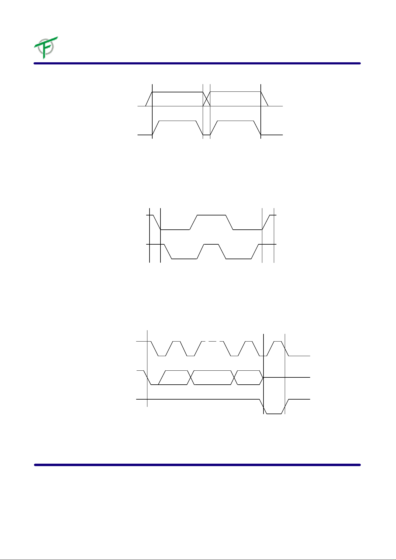
START/STOP CONDITION AND DATA TRANSITIONS:
While SCL clock is high, a high to low transition on the SDA
bus is recognized as a START condition which precedes any
read or write operation. While SCL c lock is high, a low to
high transition on the SDA bus is recognized as a STOP condition which terminates the communication and places the
IC 24LC16 into standby mode. All other data transitions
on the SDA bus must occur while SCL clock is low to ensure
proper operation.
ACKNOWLEDGE:
All data is serially transmitted in bytes (8 bits) on the SDA
bus. The acknowledge protocol is used as a handshake signal to indicate successful transmission of a byte of data. The
bus transmitter, either the master or the slave ( IC
24LC16), releases the bus after sending a byte of data on the
SDA bus. The receiver pulls the SDA bus low during the ninth
clock cycle to acknowledge the successful transmission of a
byte of data. If the SDA is not pulled low during the ninth
clock cycle, the IC 24LC16 terminates the data transmission and goes into standby mode.
For the write operation, the IC 24LC16 acknowledges
after the device address byte, acknowledges after the memory
address byte, and acknowledges after each subsequent data
byte.
For the read operation, the IC 24LC16 acknowledges
after the device address byte. Then the IC 24LC16 transmits each subsequent data byte, and the master acknowledges after each data byte transfer, indicating that it requires
more data bytes. The IC 24LC16 monitors the SDA bus
for the acknowledge. To terminate the transmission, the master does not acknowledge, and then sends a stop condition.
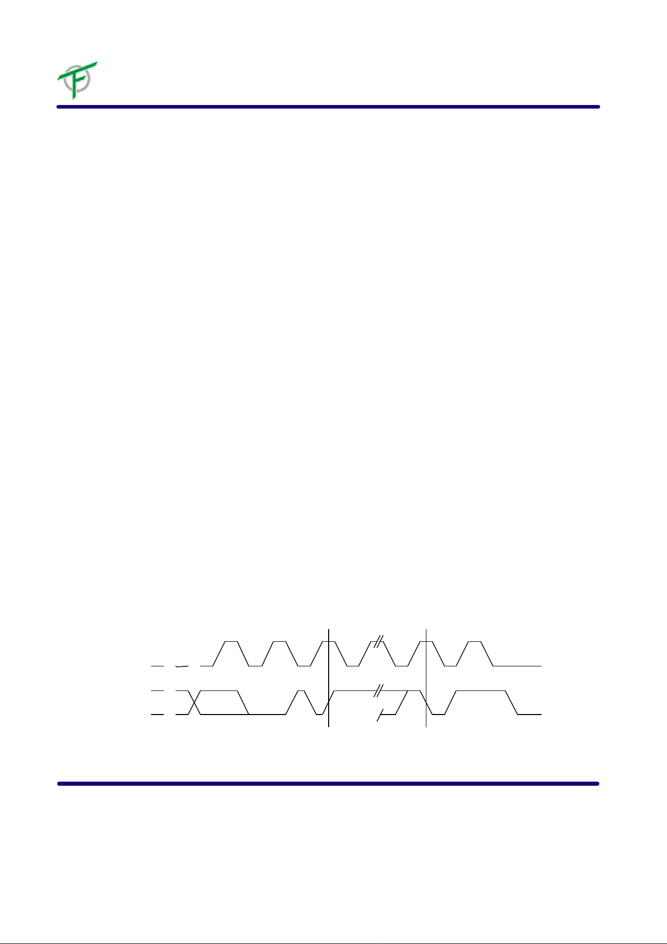
Write Cycle Timing
SCL
SDA
Note: The write cycle time tWC is the time from a valid stop condition of a write sequence to the end of the internal clear / write cycle.
深圳市科威創新元器件有限公司 電話:0755-83573495/82975811 傳真:0755-83894721 2
8th BIT ACK
WORD n
STOP START
tWC
CONDITION CONDITION
Page 3
Data Valid
SDA
SCL
SCL
DATA OUT
Start and Stop Definition
24LC16
SDA
SCL
DATA STABLE DATA STABLE
DATA
CHANGE
Output Acknowledge
DATA IN
START STOP
1 89
ACKNOWLEDGE START
深圳市科威創新元器件有限公司 電話:0755-83573495/82975811 傳真:0755-83894721 3
Page 4

24LC16
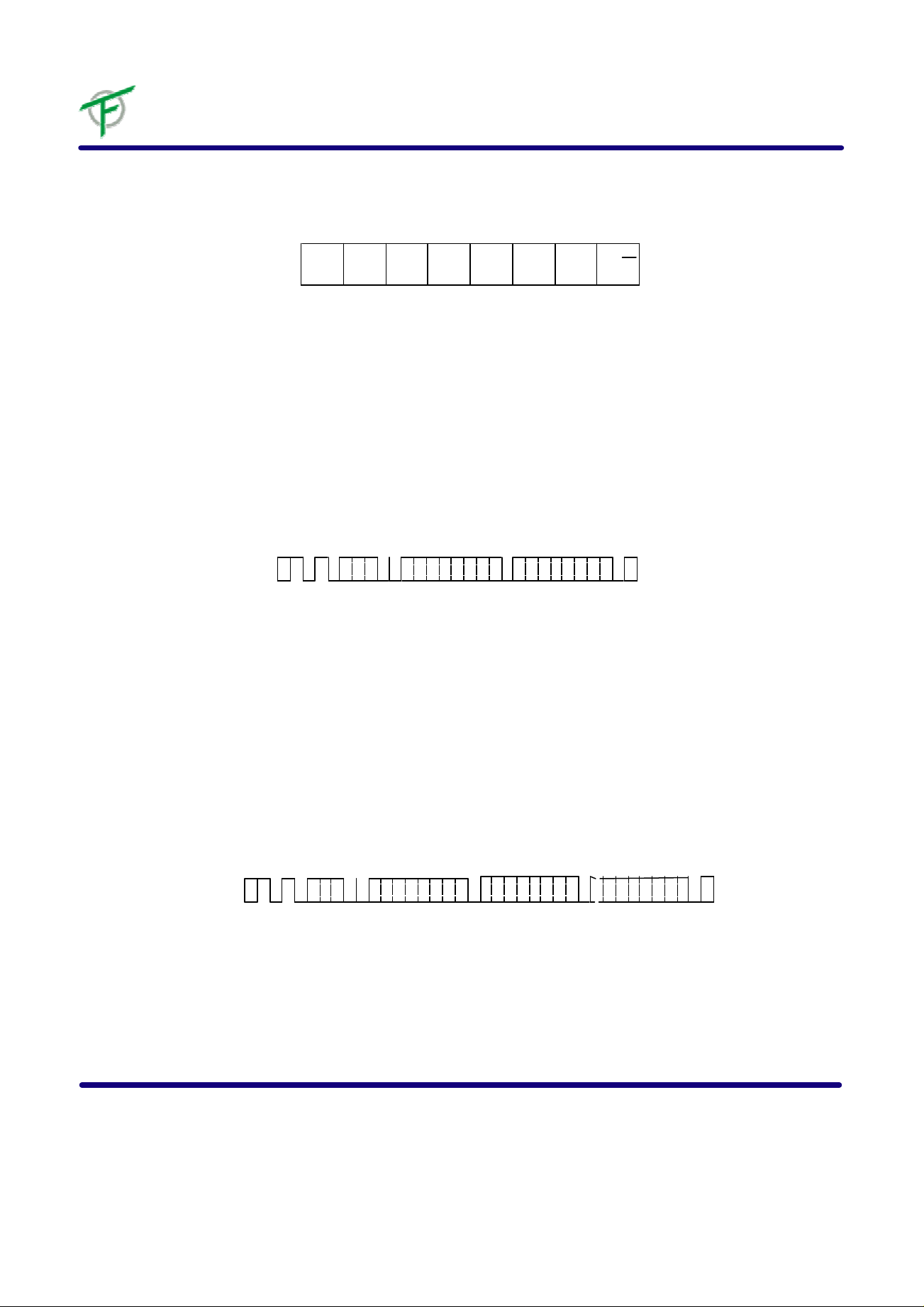
DEVICE ADDRESSING:
Following the start condition, the master will issue a device
address byte consisting of 1010 (B10) (B9) (B8) (R/W) to
access the selected IC 24LC16 for a read or write operation. The B[10:8] bits are the 3 most significant bits of the
memory address. The (R/W) bit is a high (1) for read and low
(0) for write.
DATA INPUT DURING WRITE OPERATION:
During the write operation, the IC 24LC16 latches the
SDA bus signal on the rising edge of the SCL clock.
DATA OUTPUT DURING READ OPERATION:
During the read operation, the IC 24LC16 serially shifts
the data onto the SDA bus on the falling edge of the SCL
clock.
MEMORY ADDRESSING:
The memory address is sent by the master in the form of 2
bytes. Memory address bits B[10:8], are included in the device address byte. The remaining memory address bits B[7:0]
are included in the second byte. The memory address byte
can only be sent as part of a write operation.
BYTE WRITE OPERATION:
The master initiates the byte write operation by issuing a
start condition, followed by the device address byte 1010
(B10) (B9) (B8) 0, followed by the memory address byte,
followed by one data byte, followed by an acknowledge, then
a stop condition. After each byte transfer, the IC 24LC16
acknowledges the successful data transmission by pulling
the SDA bus low. The stop condition starts the internal
EEPROM write cycle, and all inputs are disabled until the
completion of the write cycle. If the WP pin is high (1) and the
memory address is within the upper half (400-7FFH) of
memory, then the stop condition does not start the internal
write cycle and the IC 24LC16 is immediately ready for
the next command.
upper half (400-7FFH) of memory, then the stop condition
does not start the internal write cycle, and the IC 24LC16
is immediately ready for the next command.
POLLING ACKNOWLEDGE:
During the internal write cycle of a write operation in the
IC 24LC16, the completion of the write cycle can be detected
by polling acknowledge. The master starts acknowledge polling by issuing a start condition, then followed by the device
address byte 1010 (B10) (B9) (B8) 0. If the internal write
cycle is finished, the IC 24LC16 acknowledges by pulling the SDA bus low. If the internal write cycle is still ongoing,
the IC 24LC16 does not acknowledge because it's inputs are disabled. Therefore, the device will not respond to
any command. By using polling acknowledge, the system
delay for write operations can be reduced. Otherwise, the
system needs to wait for the maximum internal write cycle
time, tWC, given in the spec.
POWER ON RESET:
The IC 24LC16 has a Power On Reset circuit (POR) to
prevent data corruption and accidental write operations during power up. On power up, the internal reset signal is on
and the IC 24LC16 will not respond to any command
until the VCC voltage has reached the POR threshold value.
PAGE WRITE OPERATION:
The master initiates the page write operation by issuing a
start condition, followed by the device address byte 1010
(B10) (B9) (B8) 0, followed by the memory address byte,
followed by up to 16 data bytes, followed by an acknowledge,
then a stop condition. After each byte transfer, the IC
24LC16 acknowledges the successful dat a transmission by
pulling SDA low. After each data byte transfer, the memory
address counter is automatically incremented by one. The
stop condition starts the internal EEPROM write cycle only if
the stop condition occurs in the clock cycle immediately following the acknowledge (10th clock cycle). All inputs are dis abled until the completion of the write cycle. If the WP pin is
high (1) and the memory address is within the
深圳市科威創新元器件有限公司 電話:0755-83573495/82975811 傳真:0755-83894721 4
Page 5
Device Address
Byte Write
24LC16
1 0 1 0 B10 B9 B8 R/W
MSB LSB
S
T
A
DEVICE
R
ADDRESS WORD ADDRESS DATA
T
W
R
I
T
E
S
T
O
P
Page Write
SDA LINE
SDA LINE
M
S
B
S
T
A
DEVICE
R
ADDRESS WORD ADDRESS DATA (n)
T
M
S
B
W
R
I
T
E
L R A
S / C
B W K
L R A
S / C
B W K
A
C
K
A
C
K
A
C
K
DATA (n + x)
//
A
C
K
S
T
O
P //
A
C
K
深圳市科威創新元器件有限公司 電話:0755-83573495/82975811 傳真:0755-83894721 5
Page 6

24LC16
M
The internal memory address counter of the IC 24LC16
contains the last memory address accessed during the previous read or write operation, incremented by one. To start
the current address read operation, the master issues a start
condition, followed by the device address byte 1010 (B10)
(B9) (B8) 1. The IC 24LC16 responds with an acknowledge by pulling the SDA bus low, and then serially shifts out
the data byte accessed from memory at the location corresponding to the memory address counter. The master does
not acknowledge, then sends a stop condition to terminate
the read operation. It is noted that the memory address
counter is incremented by one after the data byte is shifted
out.
RANDOM ADDRESS READ:
The master starts with a dummy write operation (one with no
data bytes) to load the internal memory address counter by
first issuing a start condition, followed by the device address
byte 1010 (B10) (B9) (B8) 0, followed by the memory address bytes. Following the acknowledge from the IC
24LC16, the master starts the current read operation by issuing a start condition, followed by the device address byte
1010 (B10) (B9) (B8) 1. The IC 24LC16 responds with
an acknowledge by pulling the SDA bus low, and then serially shifts out the data byte accessed from memory at the
location corresponding to the memory address counter. The
master does not acknowledge, then sends a stop condition
to terminate the read operation. It is noted that the memory
address counter is incremented by one after the data byte is
shifted out.
SEQUENTIAL READ:
The sequential read is initiated by either a current address
read or random address read. After the IC 24LC16 serially shifts out the first data byte, the master acknowledges
by pulling the SDA bus low, indicating that it requires additional data bytes. After the data byte is shifted out, the
IC 24LC16 increments the memory address counter by one.
Then the IC 24LC16 shifts out the next data byte. The
sequential reads continues for as long as the master keeps
acknowledging. When the memory address counter is at the
last memory location, the counter will 'roll-over' when
incremented by one to the first location in memory (address
zero). The master terminates the sequential read operation
by not acknowledging, then sends a stop condition.
Current Address Read
Random Read
CURRENT ADDRESS READ:
SDA LINE
S
T
A
DEVICE
R
ADDRESS
T
M
S
B
SDA LINE
W
R
I
T
E
L R
S /
B W
DUMMY WRITE
S
T
A
R
DEVICE
T
ADDRESS
S
B
ADDRESS N
A
C
K
WORD
//
//
R
E
A
D DATA
L R A
S / C
B W K
A
C
K
DEVICE
R
E
A
D
N
O
A
C
K
A
C
K
S
T
O
P
S
T
DATA n ADDRESS
O
P
N
O
A
C
K
深圳市科威創新元器件有限公司 電話:0755-83573495/82975811 傳真:0755-83894721 6
Page 7
Sequential Read
S
T
A
DEVICE
R
ADDRESS DATA n DATA n +1 DATA n + 2 DATA n+3
T
SDA LINE
M
S
B
ABSOLUTE MAXIMUM RATINGS
R
E
A
D
L R
S /
B W
A
C
K
24LC16
A
C
K
A
C
K
A
C
K
S
T
O
P
N
O
A
C
K
TEMPERATURE
Storage: - 65?_ C to 150?_ C
Under Bias: -55?_ C to 125?_ C
ALL INPUT OR OUTPUT VOLTAGES
with respect to Vss +6 V to - 0.3 V
* "Absolute Maximum Ratings" may cause permanent damage to the device. This is a stress rating only and functional operation of the device at
these or any other conditions above those indicated in the operation section of this specification is not implied. Exposure to absolute maximum
rating conditions for extended periods may affect device reliability.
RECOMMENDED OPERATING CONDITIONS
Temperature Range: Commercial: 0? _ C to 70?_ C
Vcc Supply Voltage: 2.7 to 5.5 Volts
Endurance: 1,000,000 Cycles/Byte (Typical)
Data Retention: 100 Years
D.C. CHARACTERISTICS
Symbol Parameter Condition Min Max Units
Icc1 Active Vcc Current READ at 100 KHZ 0.4 1.0 mA
Icc2 Active Vcc Current WRITE at 100 KHZ
Isb Standby Current Vcc = 2.7 v
Vcc = 5.5 v 2.0 uA
Iil Input Leakage Current Vin=Vcc Max
Iol Output Leakage Current
Vil Input Low Voltage
Vih Input High Voltage
Vol2 Output Low
Vol1 Output Low
Vcc=3.0v Iol=2.1 mA 0.4 V
Vcc=2.7v Iol=-0.15 mA 0.25 V
-1.0 0.8 V
Vccx0.7 Vcc+0.5 V
3.0 mA
0.5 uA
3 uA
3 uA
深圳市科威創新元器件有限公司 電話:0755-83573495/82975811 傳真:0755-83894721 7
Page 8
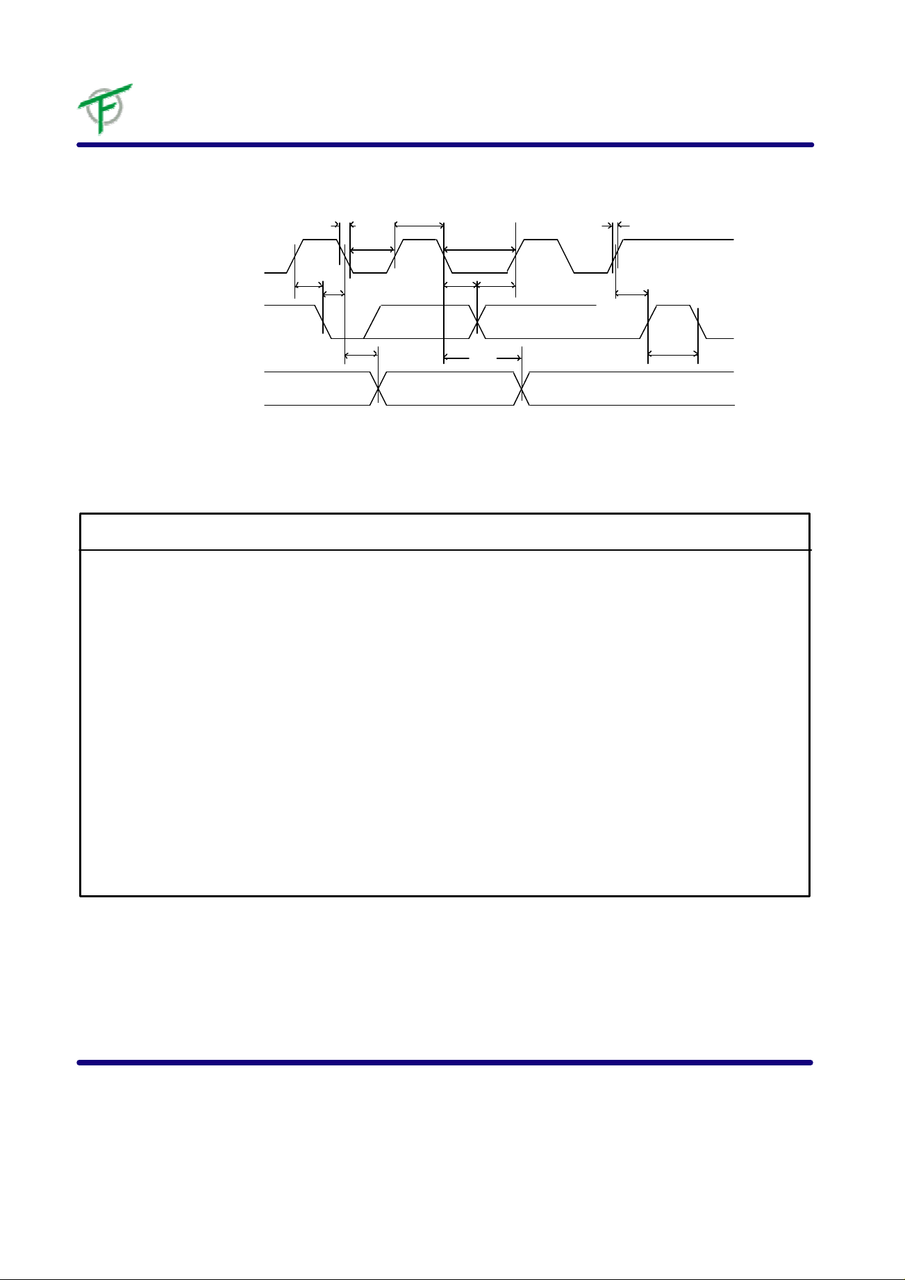
Bus Timing
Symbol Parameter 2.7 volt
24LC16
tHIGH
tLOW
tHD.DAT tSU.DAT
SCL
tF
tLOW
tSU.STA tHD.STA
SDA IN
tDH
SDA OUT
A.C. CHARACTERISTICS
5.5 volt
Min Max Min Max Units
SCL SCL Clock Frequency 100 400 kHZ
T Noise Suppression Time (1) 100 100 ns
tLOW Clock Low Period
tHIGH Clock High Period
tAA SCL Low to SDA Data Out 0.1 4.5 0.1 0.9 us
tBUF Bus Free to New Start (1) 4.7 1.2 us
tHD.STA Start Hold Time
tSU.STA Start Set-up Time
tHD.DAT Data-in Hold Time
tSU.DAT Data-in Set-up Time
tR SCL and SDA Rise Time (1) 1.0 0.3 us
tF SCL and SDA Fall Time (1) 300 300 ns
tSU.STO Stop Set-up Time
tDH Data-out Hold Time
tWC Write Cycle Time
4.7 1.2 us
4.0 0.6 us
4.0 0.6 us
4.7 0.6 us
0 0 us
200 100 ns
4.7 0.6 us
100 50 ns
10 10 ms
tR
tSU.STO
tBUF tAA
Note: 1 This parameter is characterized and not 100% tested.
深圳市科威創新元器件有限公司 電話:0755-83573495/82975811 傳真:0755-83894721 8
 Loading...