

Page 1
20SQ045-3G
Pb
E
L
V
W
E
E
E
R
o
H
S
Halogen
FREE
Type
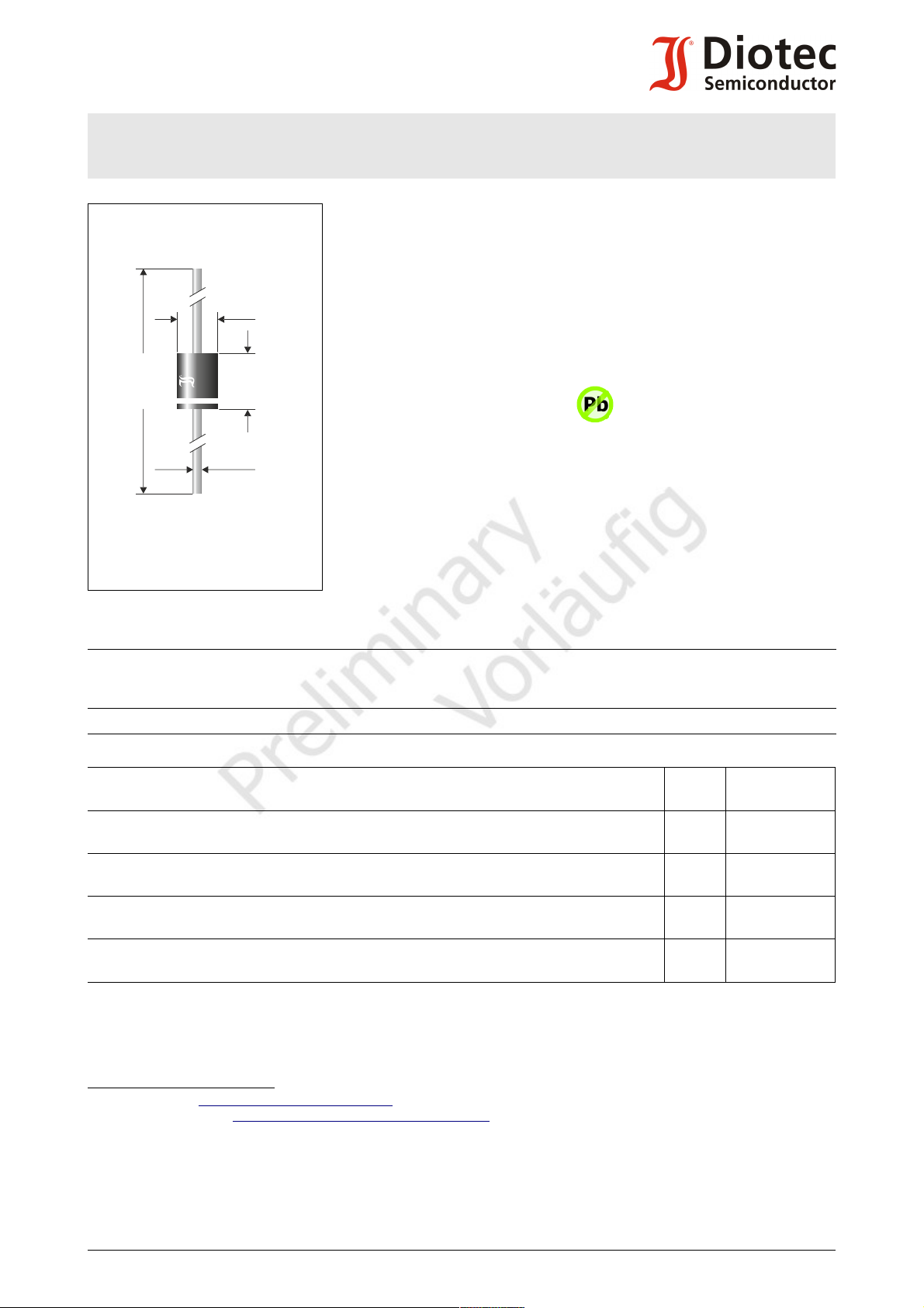
Ø 1.2
±0.05
Ø 5.4
±0.1
62.5
±0.5
7.5
±0.1
Schottky Barrier Rectifier Diodes 3rd Generation
Schottky-Gleichrichterdioden 3. Generation
Version 2018-09-27
Ø 5.4 x 7.5
Dimensions - Maße [mm]
20SQ045-3G
I
V
T
Typical Applications
Solar Bypass Diodes, Polarity
Protection, Free-wheeling diodes,
Output Rectification in DC/DC
Converters
Commercial grade 1)
Features
Best trade-off between VF and IR 2)
Much smaller package outline
than industry standard
Compliant to RoHS, REACH,
Conflict Minerals 1)
FAV
F@5A
jmax
= 20 A
< 0.43 V
= 150°C
Optimale Auswahl von VF und IR 2)
V
= 45 V
RRM
I
= 310/350 A
FSM
V
~ 0.25 V @ 5 A
F125
Typische Anwendungen
Solar-Bypassdioden,
Verpolschutz, Freilaufdioden,
Ausgangsgleichrichtung in
Gleichstromwandlern
Standardausführung 1)
Besonderheiten
Gehäusegröße sehr viel kleiner
als Industriestandard
Konform zu RoHS, REACH,
Konfliktmineralien 1)
Mechanical Data 1) Mechanische Daten 1)
Taped in ammo pack
On request: on 13” reel
500
1000
Gegurtet in Ammo-Pack
Auf Anfrage: auf 13” Rolle
Weight approx. 1.7 g Gewicht ca.
Case material UL 94V-0 Gehäusematerial
Solder & assembly conditions 260°C/10s Löt- und Einbaubedingungen
MSL N/A
Maximum ratings 3) Grenzwerte 3)
Type
Typ
Repetitive peak reverse voltage
Periodische Spitzensperrspannung
V
[V]
RRM
Surge peak reverse voltage
Stoßspitzensperrspannung
V
[V]
RSM
20SQ045-3G 45 45
Max. average forward rectified current
Dauergrenzstrom in Einwegschaltung
Peak forward surge current
Stoßstrom in Fluss-Richtung
Rating for fusing
Grenzlastintegral
Junction temperature – Sperrschichttemperatur
in DC forward mode – bei Gleichstrom-Durchlassbetrieb
Storage temperature
Lagerungstemperatur
Half sine-wave
Sinus-Halbwelle
TA = 50°C I
50 Hz (10 ms)
60 Hz (8.3 ms)
FAV
I
FSM
20 A 4)
310 A
350 A
t < 10 ms i2t 480 A2s
T
j
T
j
T
S
-50...+150°C
≤ 200°C
2,5
-50...+150°C
)
1 Please note the detailed information on our website or at the beginning of the data book
Bitte beachten Sie die detaillierten Hinweise auf unserer Internetseite bzw. am Anfang des Datenbuches
2 For more details, ask for the Diotec Application Note “Reliability of Bypass Diodes”
Weitere Infos in der Diotec Applikationsschrift „Reliability of Bypass Diodes”
3 TA = 25°C unless otherwise specified – TA = 25°C wenn nicht anders angegeben
4 Valid, if leads are kept at ambient temperature at a distance of 10 mm from case
Gültig, wenn die Anschlussdrähte in 10 mm Abstand vom Gehäuse auf Umgebungstemperatur gehalten werden
5 Meets the Requirements of IEC 61215 bypass diode thermal test
Erfüllt die Anforderungen des IEC 61215 Bypass-Diodentests
© Diotec Semiconductor AG http://www.diotec.com/ 1
Page 2

20SQ045-3G
Forward characteristics (typical values)
Durchlasskennlinien (typische Werte)
10
10
1
10
10
2
-1
-2
[A]
I
F
0
V
F
0.4 0.6
[V]
1.0
T = 25°C
j
T = 125°C
j
120
100
80
60
40
20
0
[%]
I
FAV
Rated forward current versus ambient temperature )
Zul. Richtstrom in Abh. von der Umgebungstemp. )
1
1
[°C]
T
A
150100
50
0
10
2
10
1
1
10
-1
10
-2
[mA]
I
R
0
V
RRM
40 60 80 100
[%]
Typ. i nstantan eous leak ag e cu rren t v s. rev. v oltage
Typ. S p errstrom ( Au genb li ckswert) ü . Sp errsp an nu n g
T = 2 5 °C
j
T = 1 0 0 °C
j
T = 1 2 5 °C
j
T = 7 5°C
j
T = 5 0°C
j
T = 1 5 0 °C
j
Characteristics Kennwerte
Type
Typ
20SQ045-3G
typ. 0.25
Forward voltage
Durchlass-Spannung
VF [V] @ IF [A] @ T
< 0.43
5
25°C
125°C
Forward voltage
Durchlass-Spannung
j
VF [V] @ IF [A] @ T
j
< 0.55 20 25°C
Leakage current
Sperrstrom
Tj = 25°C
Tj = 100°C
VR = V
RRM
Typical junction capacitance – Typische Sperrschichtkapazität VR = 4 V C
Typical thermal resistance junction to ambient
Typischer Wärmewiderstand Sperrschicht-Umgebung
Typical thermal resistance junction to lead (at the case)
Typischer Wärmewiderstand Sperrschicht-Anschlussdraht (am Gehäuse)
R
R
I
R
j
thA
thL
< 200 µA
typ. 10 mA
720 pF
12 K/W 1)
2.5 K/W 2)
1 Valid, if leads are kept at ambient temperature at a distance of 10 mm from case
Gültig, wenn die Anschlussdrähte in 10 mm Abstand vom Gehäuse auf Umgebungstemperatur gehalten werden
2 Valid, if leads are kept at ambient temperature at a distance of 3 mm from case
Gültig, wenn die Anschlussdrähte in 3 mm Abstand vom Gehäuse auf Umgebungstemperatur gehalten werden
2 http://www.diotec.com/ © Diotec Semiconductor AG
Disclaimer: See data book page 2 or website
Haftungssauschluss: Siehe Datenbuch Seite 2 oder Internet
 Loading...