

Datasheet 2085-6017-00, 2085-6016-00, 2085-6015-00, 2085-6014-00, 2085-6013-00 Datasheet (M A COM manufacturer of RF)
...Page 1
Back Diode Detector
2085 Series
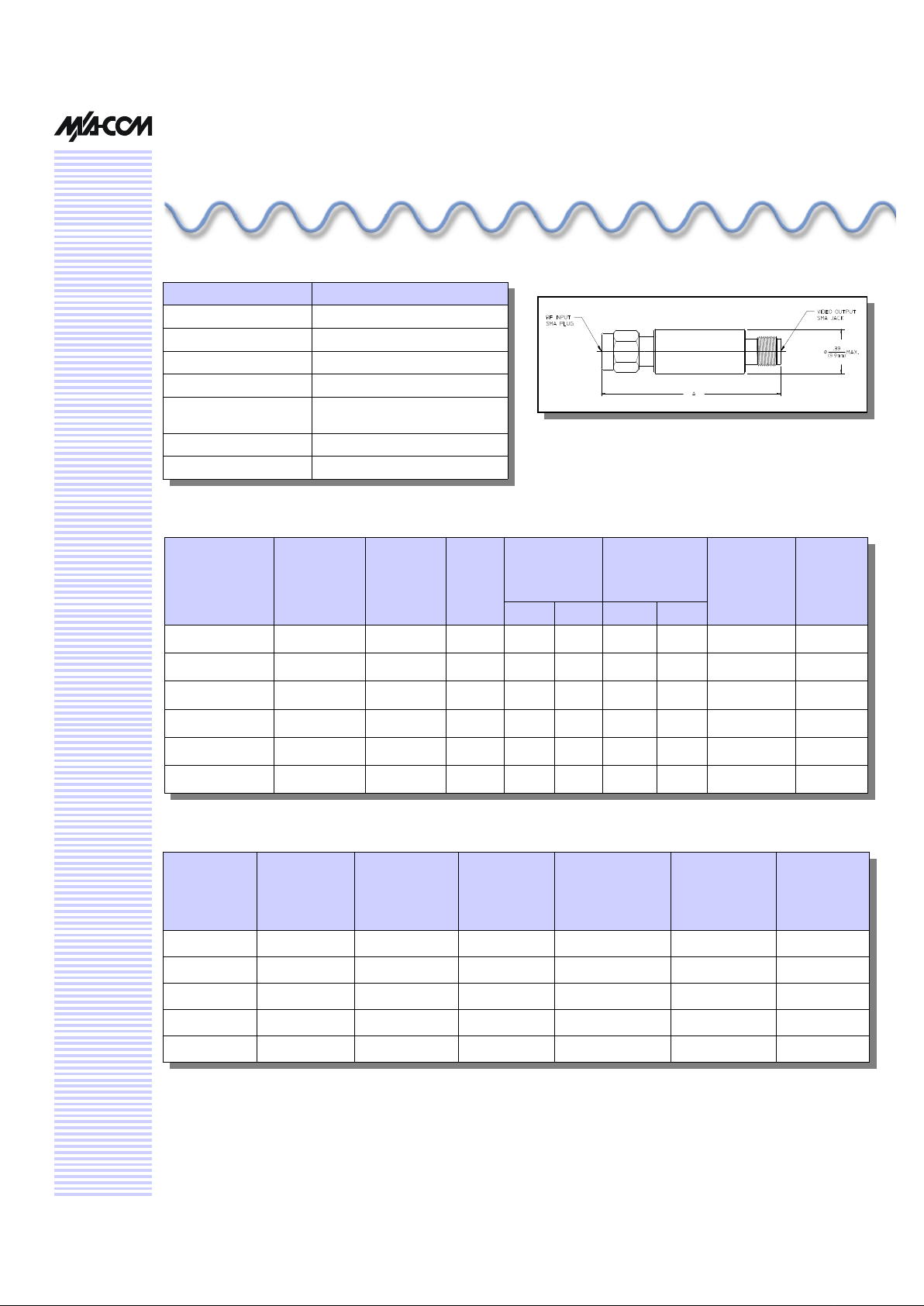
Mechanical Outline Drawing
V 3.00
Specifications
Detector
Part Number
Frequency
Range (GHz)
Flatness1
Typical
(± dB)
VSWR1
Typical
Open
Circuit
Sensitivity2
(mV/mW)
Tangential
Sensitivity
3
(-dBm)
Output
Capacitance
Typical (pF)
Typ. Min Typ. Min.
2085-6010-00 1.0 - 18.0 1.5 4.0 500 400 47.0 46.0 12
2085-6013-00 1.0 - 2.0 0.2 2.5 780 700 53.0 52.0 18
2085-6014-00 2.0 - 4.0 0.3 1.8 840 750 53.5 52.5 18
2085-6015-00 4.0 - 8.0 0.4 2.5 610 525 52.0 51.0 12
2085-6016-00 8.0 - 12.4 0.5 2.0 640 550 52.5 51.5 12
2085-6017-00 12.4 - 18.0 0.5 2.5 600 500 52.0 51.0 9
Dim. A
Inches
(mm)
1.35 (34.3)
1.35 (34.3)
1.55 (39.4)
1.55 (39.4)
1.55 (39.4)
1.55 (39.4)
Parameter Specification
Bias Current 0
Output Polarity Negative 4
Video Resistance 80 Ohms Nominal 2
Maximum Power 40 mW CW or 3 erg spike
Temperature Stability ± 1 dB over operating range
of –65°C to +100°C
Temperature Range -65°C to +100°C
Finish Passivated Stainless Steel
Detector
Part Number
Frequency
Range (GHz)
Flatness1
Typical
(± dB)
VSWR1
Typical
Open
Circuit
Sensitivity2
(mV/mW)
Typical
Tangential
Sensitivity
3
(-dBm)
Output
Capacitance
Typical (pF)
2085-6013-00 0.85 - 6.0 1.0 3:1 500 50.0 18
2085-6014-00 1.4 - 5.0 1.0 3:1 500 50.0 18
2085-6015-00 3.9 - 9.5 1.0 3:1 500 50.0 12
2085-6016-00 6.5 - 14.0 1.0 3:1 400 49.0 12
2085-6017-00 2.7 - 18.5 1.0 3:1 400 49.0 9
Typical Extended Band Performance
1. For RF Power levels below -20 dBm, and with 1,000 ohm load.
2. For RF power levels below -20 dBm.
3. With video amplifier of 1 MHz bandwidth, and 2 dB noise figure.
4. For Positive Output change suffix to -13.
 Loading...