

Page 1
*RoHS Directive 2002/95/EC Jan 27 2003 including Annex
Specifications are subject to change without notice.
Customers should verify actual device performance in their specific applications.
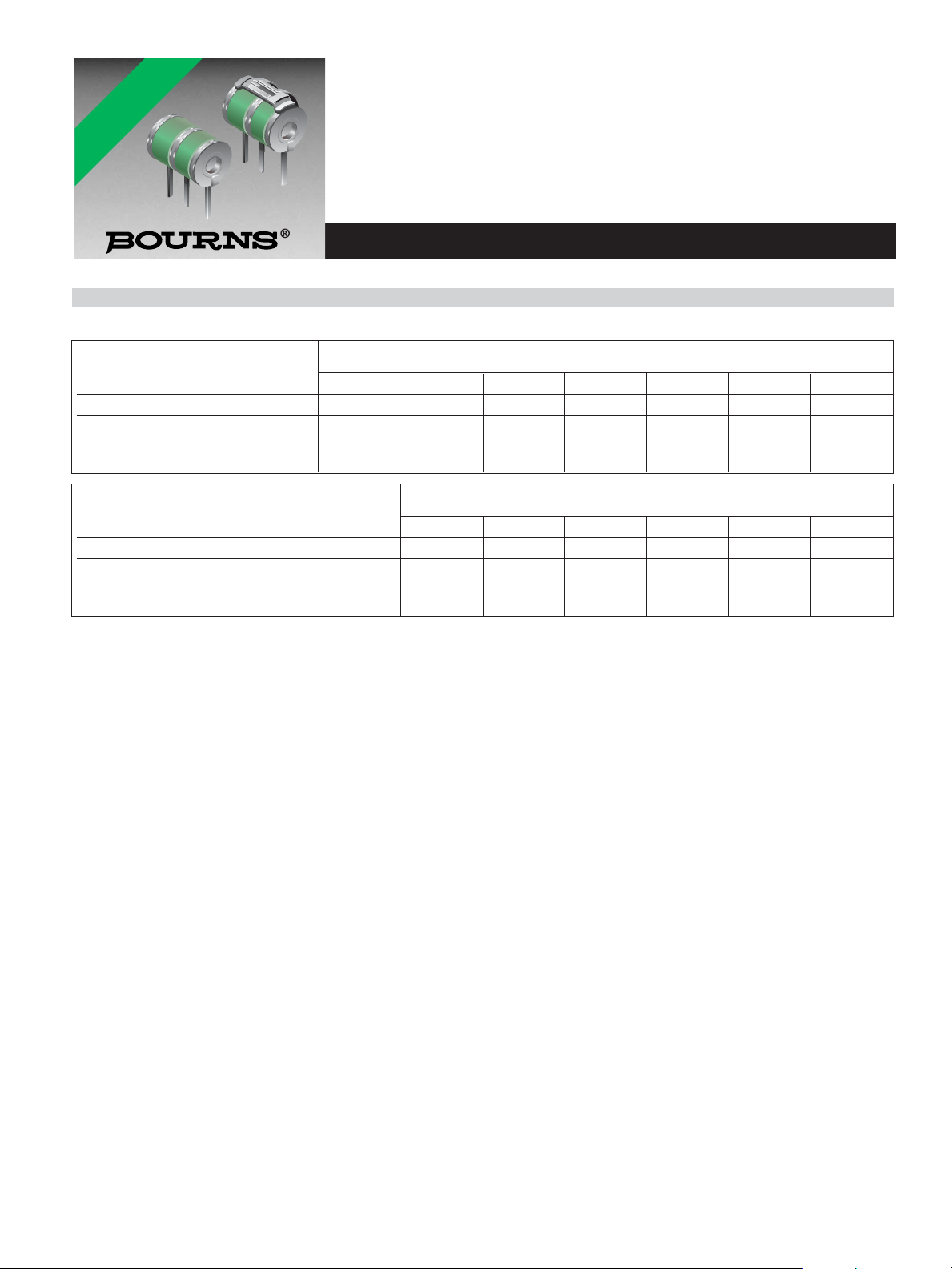
2026 Series - 3-Pole Gas Discharge Tube
Features
■ Balanced TRIGARD
®
■ Approximately 8 mm diameter, 11 mm long
■ UL recognized
■ Custom configurations available
■ High surge current rating
■ Stable breakdown throughout life
■ RoHS compliant* version available
Applications
■ Telecommunications
■ Industrial electronics
■ Commercial electronics
■ Consumer electronics
■ Automotive, aircraft, military electronics
Impulse Transverse Delay ......................................1000 V/µs.....................................................................< 75 ns
Insulation Resistance.............................................100 V (50 V for Model 2026–07 & 2026-09).................> 10
10
Ω
Glow Voltage..........................................................10 mA...........................................................................~ 70 V
Arc Voltage.............................................................1A.................................................................................~ 10 V
Glow-Arc Transition Current........................................................................................................................< 0.5 A
Capacitance...........................................................1 MHz...........................................................................< 2 pF
DC Holdover Voltage
2
...........................................>135 V, (52 V for Model 2026-07 & 2026-09,...............< 150 ms
80 V for Model 2026-15)
Impulse Discharge Current ....................................40000 A, 8/20 µs
3
......................................................... 1 operation minimum
20000 A, 8/20 µs..........................................................> 10 operations
1000 A, 10/1000 µs .....................................................> 400 operations
Alternating Discharge Current................................130 Arms, 11 cycles
3
................................................... 1 operation minimum
20 Arms, 1 s.................................................................> 10 operations
Operation and Storage Temperature, Climatic Category (IEC 60068-1) 40/ 90/ 21.................................... -40 to +90 °C
Optional Switch-Grade Fail-short device available.
Notes:
• UL recognized component, UL File E153537.
• Model number marking on tube: 26-xxx V.
• The rated discharge current for TRIGARD
¤
Gas Discharge Tubes is the total current equally divided between each line to ground.
• Sparkover limits after life ±25 %, IR >10
8
Ω (-25 %,+30 % for Model 2026-07, 2026-09 and 2026-60).
• Line to Line voltage is approximately 1.8 to 2 times the stated Line to Ground breakdown voltage.
• At delivery AQL 0.65 Level II, DIN ISO 2859
1
Tube meets BT requirement Type 14 A/1 (210-310 V).
2
Network applied.
3
DC Sparkover may exceed ±25 % after discharge, but will continue to protect without venting.
Characteristics
Test Methods per ITU-T (CCITT) K.12, IEEE C62.31, RUS PE-80, Telcordia GR 1361
*RoHS COMPLIANT
VERSIONS
AVAILABLE
Characteristic
Model No.
2026-07 2026-09 2026-15 2026-20 2026-23 2026-25 2026-26
DC Sparkover ±20 % @ 100 V/s 75 V 90 V 150 V 200 V 230 V 250 V 260V
1
Impulse Sparkover
100 V/µs 275 V 275 V 350 V 425 V 450 V 475 V 475 V
1000 V/µs 700 V 600 V 575 V 625 V 650 V 700 V 700 V
Characteristic
Model No.
2026-30 2026-35 2026-40 2026-42 2026-47 2026-60
DC Sparkover ±20 % @ 100 V/s 300 V 350 V 400 V 420 V 470 V 600 V
Impulse Sparkover
100 V/µs 500 V 625 V 675 V 725 V 800 V 925 V
1000 V/µs 775 V 875 V 925 V 1000 V 1100 V 1250 V
Page 2
Specifications are subject to change without notice.
Customers should verify actual device performance in their specific applications.
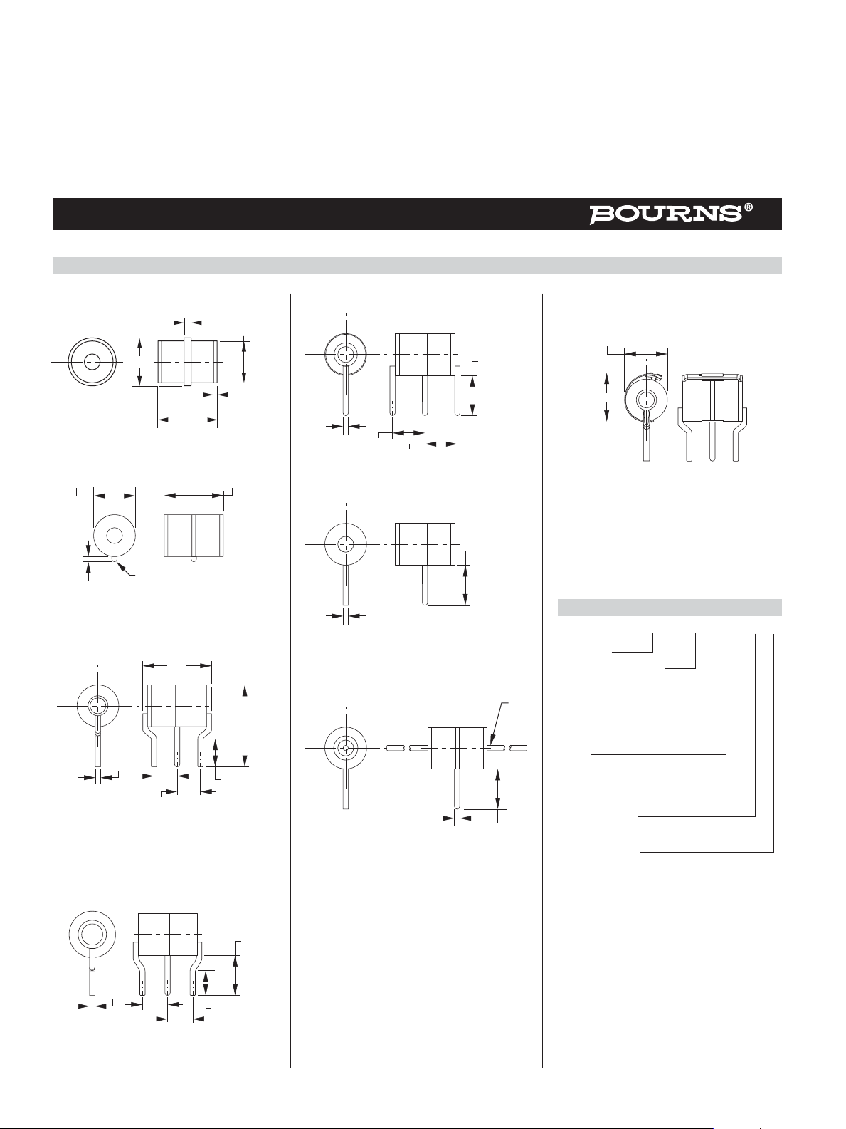
DIMENSIONS: MILLIMETERS
UNITS WITH LEADS ARE BASED ON THE
2026-XX-A1 BODY.
2026 Series - 3-Pole Gas Discharge Tube
Product Dimensions (additional lead form configurations available upon request)
2026-XX-A
2026-XX-A1
2026-XX-C2
2026-XX-C3
2026-XX-C4
2026-XX-C8
2026-XX-C
1.0 mm dia. lead wire
1.0 DIA.
30
LONG
2 PLCS.
7.5
FAIL-SHORT CONFIGURATION
2026-XX-C2F SHOWN
How To Order
2026 - nn - x n F LF
Model Number
Designator
Voltage (Divided by 10)
07 = 75 V 30 = 300 V
09 = 90 V 35 = 350 V
15 = 150 V 40 = 400 V
20 = 200 V 42 = 420 V
23 = 230 V 47 = 470 V
25 = 250 V 60 = 600 V
26 = 260 V
Leads
A = None
C = 1 mm
Lead Shape
(See Product Dimension Drawings)
Fail-Short Option
Blank = Standard Product
F = With Fail-Short Mechanism
Lead Free Option
Blank = Standard Product
LF = Lead Free/RoHS Compliant Product
0.7 - 1.0
1.0 DIA.
6.1
6.1
8.1
7.5
9.6
1.6
9.0
11.7
7.8
0.6
7.9
11.2 REF.
1.0 DIA.
4.4
1.0 DIA.
7.5
1.0 DIA.
13.0
MAX.
15.4
4.5
4.4
1.0 DIA.
4.75
4.75
7.5
4.4
Page 3
REV. 04/09
Specifications are subject to change without notice.
Customers should verify actual device performance in their specific applications.
2026 Series - 3-Pole Gas Discharge Tube
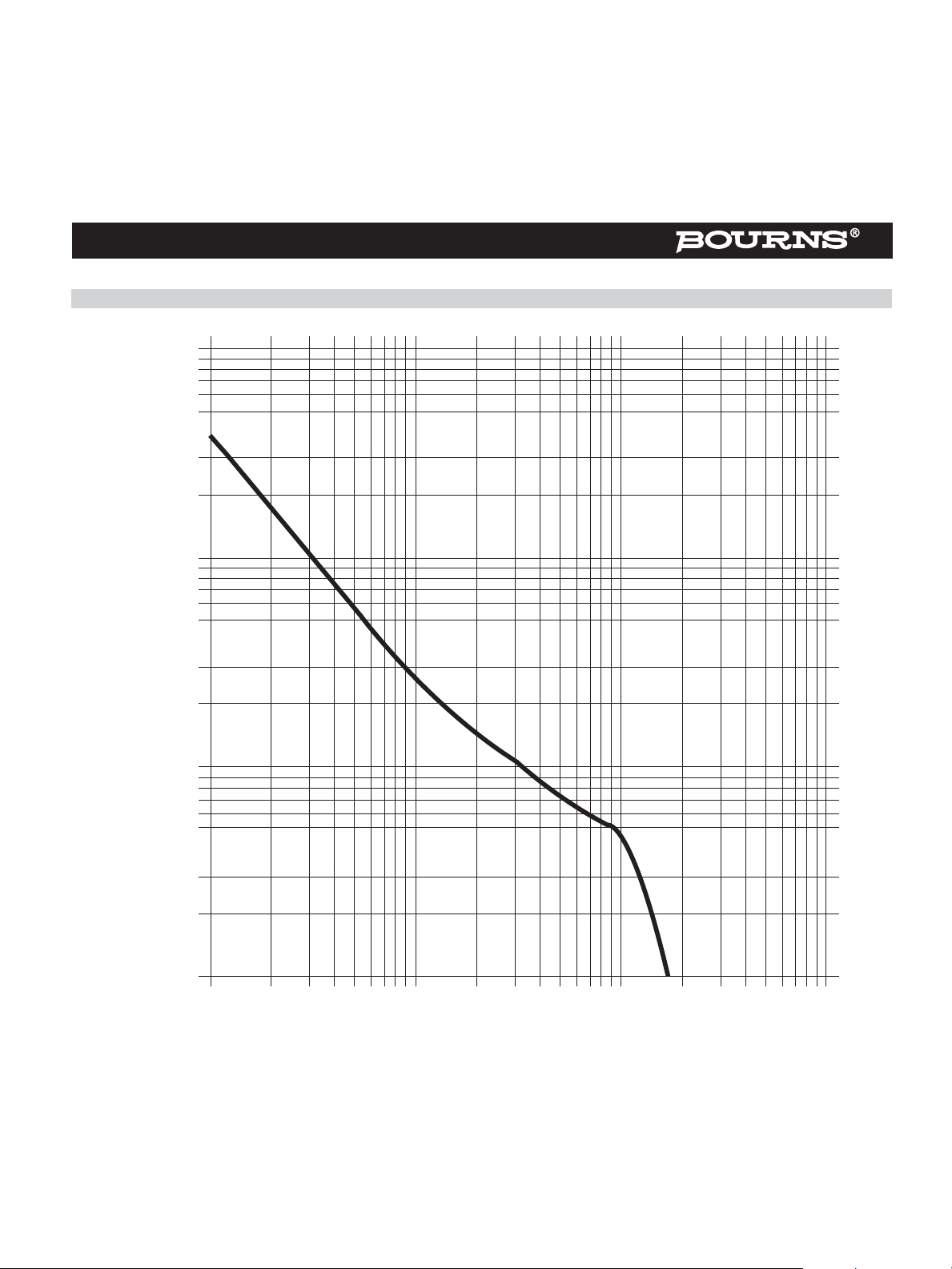
Switch-Grade Fail-short Device Shorting Curve 2026-XX-XF
30.0
20.0
10.0
5.0
Current (A) (ELTGS)
1.0
0.5
0.1
1
ELTGS = Each Line to Ground Simultaneously
NOTE: When using a GDT fail-short device, it is imperative that all components associated and
connected to the GDT with failsafe be tested in their respective completely integrated environment
(finished product) to assure desired operation.
10 100
1000
Seconds
 Loading...