

Page 1
—1—
E99220-TE
Sony reserves the right to change products and specifications without prior notice. This information does not convey any license by
any implication or otherwise under any patents or other right. Application circuits shown, if any, are typical examples illustrating the
operation of the devices. Sony cannot assume responsibility for any problems arising out of the use of these circuits.
Absolute Maximum Ratings (Ta=25 °C)
• Reverse voltage VR 15 V
• Operating temperature Topr –20 to +75 °C
• Storage temperature Tstg –65 to +150 °C
Description
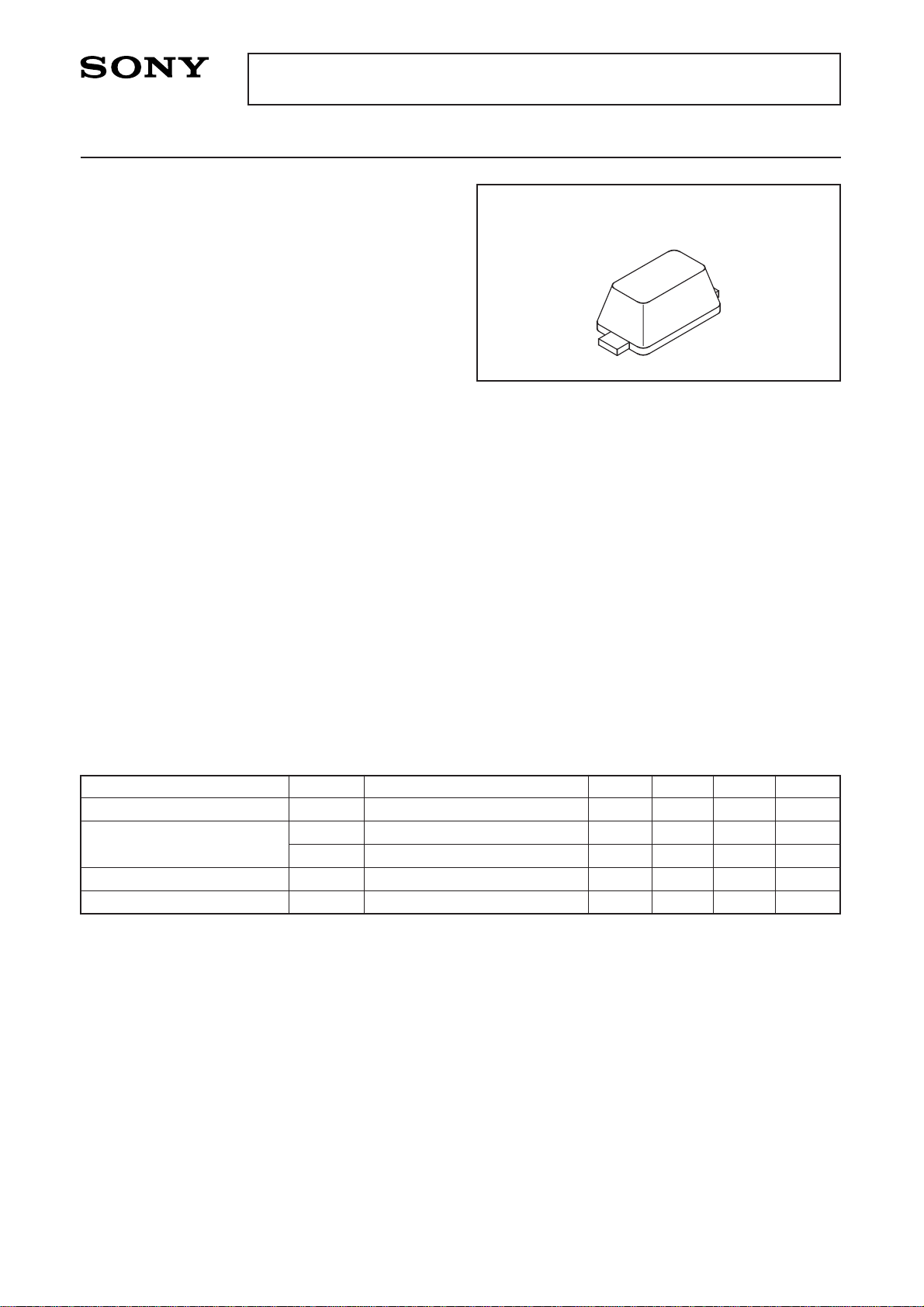
The 1T413 is a variable capacitance diode
designed for the digital cellular phone VCO using a
super-small-miniature flat package (SSVC).
Features
• Super-small-miniature flat package
• Low series resistance: 0.40 Ω Max. (f=470 MHz)
• Large capacitance ratio: 2.90 Typ. (C1/C4)
• Small leakage current: 10 nA Max. (VR=15 V)
Applications
Digital cellular phone VCO
Structure
Silicon epitaxial planar type diode
Variable Capacitance Diode
M-290
1T413
Electrical Characteristics (Ta=25 °C)
Item
Reverse current
Diode capacitance
Capacitance ratio
Series resistance
Symbol
IR
C1
C4
C1/C4
rs
Conditions
VR=15 V
VR=1 V, f=1 MHz
VR=4 V, f=1 MHz
VR=1 V, f=470 MHz
Min. Typ. Max. Unit
10.0 nA
15.0 17.5 pF
5.1 6.1 pF
2.5 2.9
0.40 Ω
Page 2
—2—
1T413
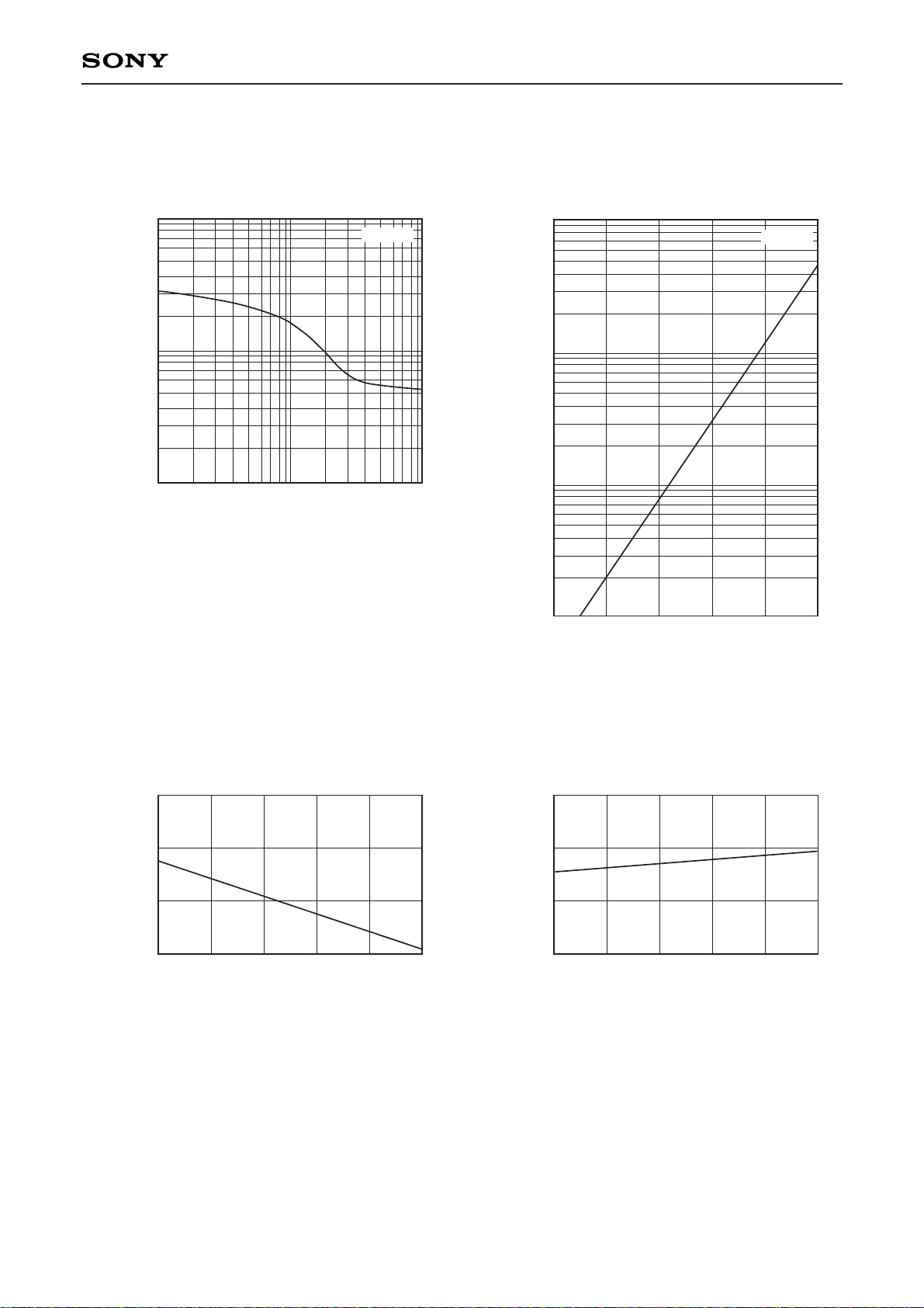
Example of Representative Characteristics
100
10
1
C-Diode capacitance (pF)
VR-Reverse voltage (V)
0.1 1
Forward voltage vs. Ambient temperature
0.80
0.90
0.70
0.60
–20
VF-Forward voltage (V)
Ta-Ambient temperature (°C)
I
F=1mA
0 20406080
Reverse current vs. Ambient temperatureDiode capacitance vs. Reverse voltage
IR-Reverse current (pA)
Ta-Ambient temperature (°C)
–20 0 20 40 60 80
Reverse voltage vs. Ambient temperature
30
35
25
20
–20
VR-Reverse voltage (V)
Ta-Ambient temperature (°C)
I
R=10µA
0 20406080
5
20
50
2
0.2 0.5 2 5 10
10
1
0.1
VR=15V
Ta=25°C
Page 3
—3—
1T413
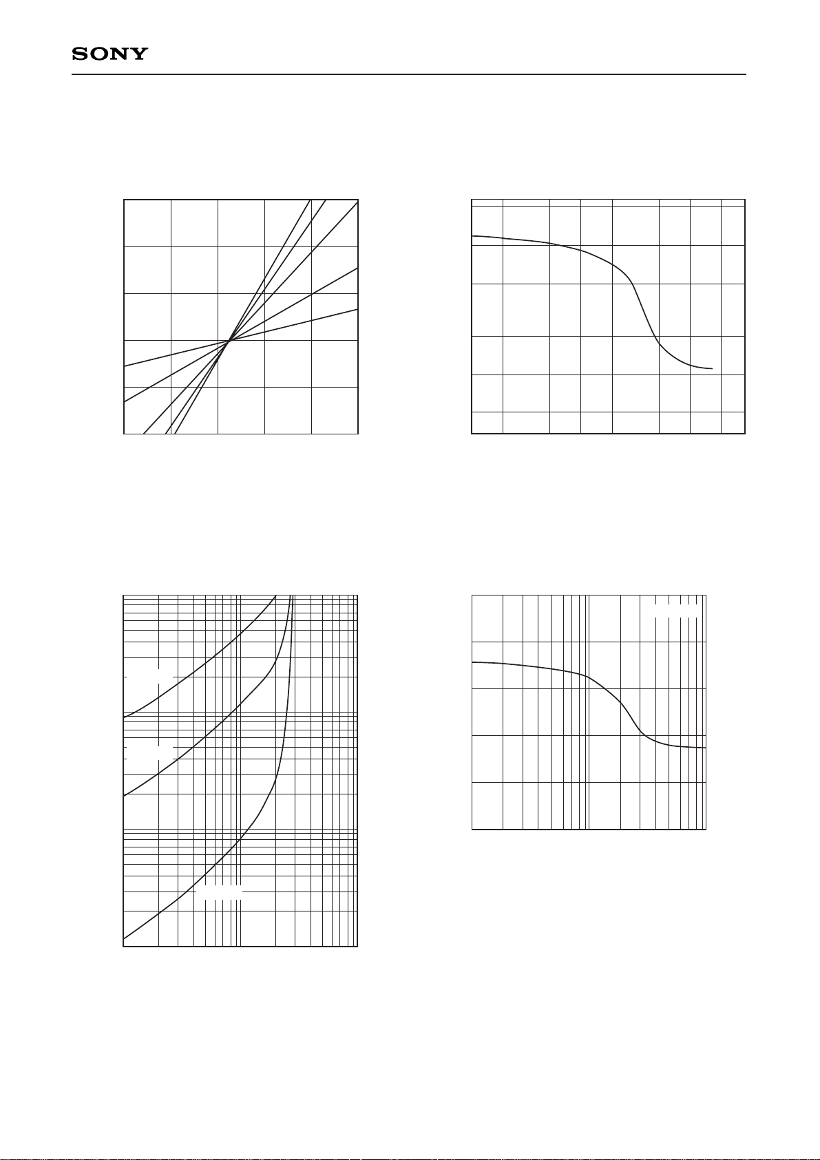
Diode capacitance vs. Ambient temperature
1.03
1.02
1.00
1.01
0.99
0.98
Ta-Ambient temperature (°C)
–20020406080
C (Ta)/C (25°C)-Diode capacitance
Reverse current vs. Reverse voltage
100
10
1
0.1
V
R-Reverse voltage (V)
1 3 10 30
IR-Reverse current (pA)
VR=2VVR=1V
V
R=3V
V
R=10V
V
R=4V
Temperature coefficient of diode capacitance
1000
2000
200
500
30
50
100
V
R-Reverse voltage (V)
0.1 0.5 1.00.2 2.0 5.0 10.0 20.0
Temperature coefficient (ppm/°C)
Ta=80°C
Ta=60°C
Ta=25°C
0.5
0.3
0.0
rs-Series resistance (Ω)
VR-Reverse voltage (V)
0.1 1
Series resistance vs. Reverse voltage
f=470MHz
0.2
0.4
0.1
10
Page 4
SONY CODE
EIAJ CODE
JEDEC CODE
PACKAGE MATERIAL
LEAD TREATMENT
LEAD MATERIAL
PACKAGE WEIGHT
EPOXY RESIN
SOLDER PLATING
COPPER
b
1.7 ± 0.1
10° MAX
c
0.8 ± 0.1
10° MAX
0.7 ± 0.1
c
b
0.11 ± 0.005
0.3 ± 0.025
BASE METAL
0.11
–
0.01
0.3
– 0.02
WITH PLATING
+ 0.05
+ 0.05
M-290
0.2 ± 0.05
0.002g
M-290
1.3 ± 0.1
M
A
0.2
A
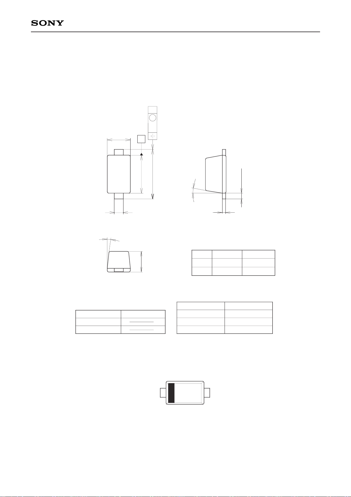
Package Outline Unit : mm
1T413
—4—
Mark
X3
1
2
1 FCathode
2 FAnode
 Loading...