

Page 1
Surface Mount Switching Diode
Lead(Pb)-Free
P b
1
1SS355
SWITCHING DIODE
100m AMPERES
100VOLTS
S
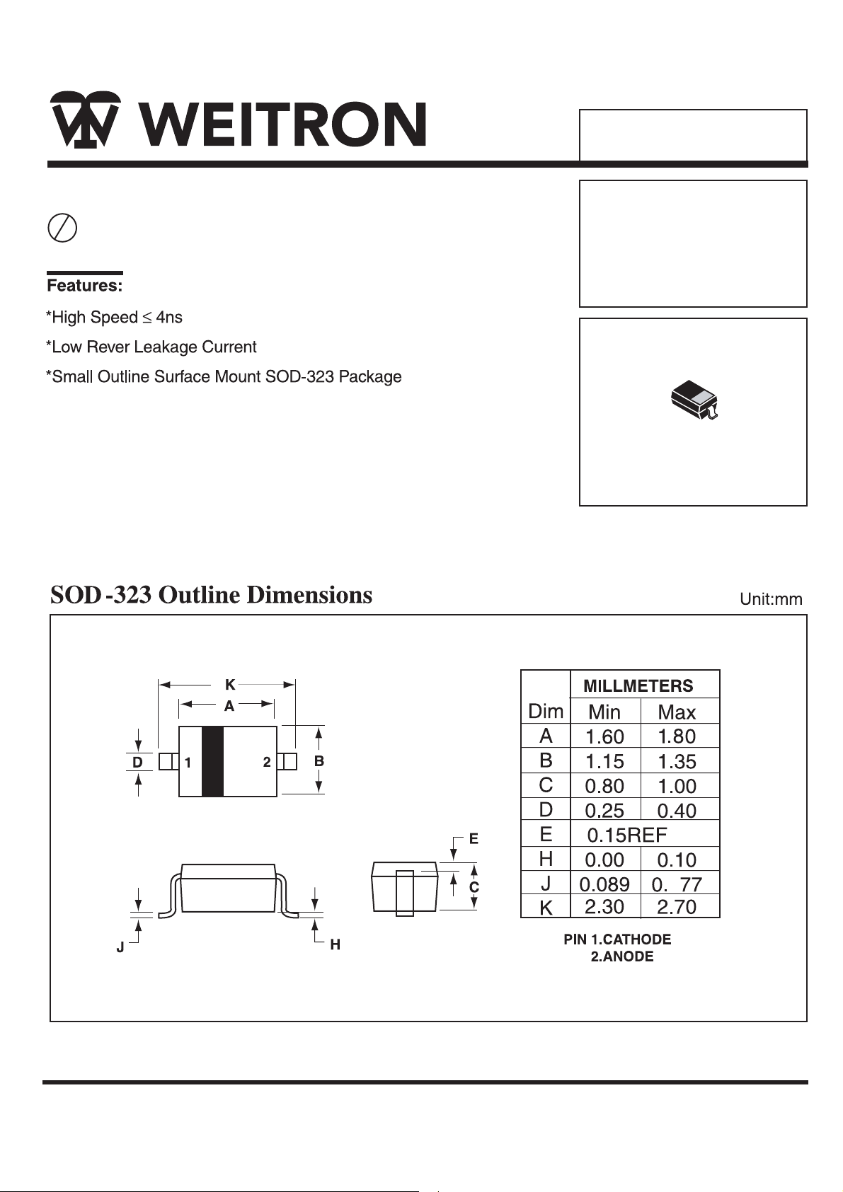
OD-323
WEITRON
http://www.weitron.com.tw
Page 2
1SS 355
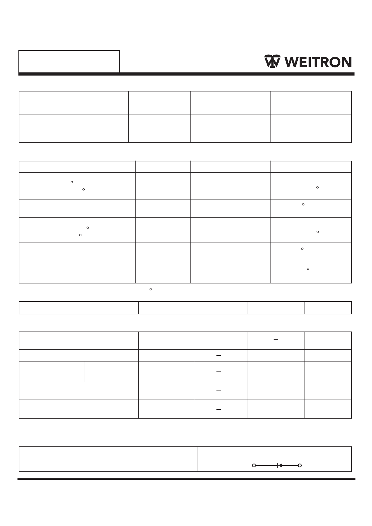
Maximum Ratings
Rating Symbol Value Unit
Reverse Voltage
Forward Current
Peak Forward Surge Current
Thermal Characteristics
Characterictics Symbol Max Unit
Total Device Dissipation FR-5
Board TA=25 C
Derate Above 25 C
Thermal Resistance, Junction
to Ambient
Total Device Dissipation Alumina
Substrate,
Derate Above 25 C
Thermal Resistance, Junction to
Ambient
Junction and Storage
Temperature
(2)
TA=25 C
VR
IF
IFM(Surge)
PD
q
R JA
PD
q
R JA
TJ, Tstg
100
100
500
225
1.8
556
300
2.4
417
-55 to + 150
Vdc
mAdc
mAdc
mW
mW/ C
C/W
mW
mW/ C
C/W
C
Electrical Characteristics
Characterictics Symbol Max Unit
(TA=25 C Unless Otherwise note)
Min
Off Characteristics
Reverse Breakdown Votalge
(IR=100µAdc)
Forward Voltage(IF=100mAdc)
Reverse Voltage
Leakage Current
Diode Capacitance
(VR=0.5V, f=1.0MHz)
Revarse Recover Time
(IF=IR=10mAdc)
1. FR-5=1.0x0.75x0.062 in 2.Alumina=0.4x0.3x0.024 in. 99.5% alumina.
(VR=80Vdc)
V(BR)
VF
IR
CT
trr
100
1200
0.1
3.5
4.0
Device Marking
Item Marking Eqivalent Circuitdiagram
1SS 355 5D
1
Vcc
mV dc
µAdc
pF
ns
2
WEITRON
http://www.weitron.com.tw
Page 3

1SS 355
820
+10V
0.1µF
2.0K
100 µH
I
t
I
F
0.1µF
t
p
r
10%
t
F
t
rr
t
50 OUTPUT
PULSE
GENERATOR
1000
100
10
, FORWARD CURRENT (mA)
1
F
I
D.U.T.
50 INPUT
SAMPLING
OSCILLOSCOPE
Notes:1. A 2.0 k variable resistor for a Forward Current (IF) 0f 10 mA
2. Input pules is adjusted so IR(peak) is equal to 10 mA
3. t
»
t
p
rr
V
R
90%
INPUT SIGNAL
Figure 1. Recovery Time Equivalent Test Circuit
120
100
Scattering Limit
80
60
40
, REVERSE CURRENT (nA)
R
I
Scattering Limit
20
I
=1.0mA
I
R
R(REC)
OUTPUT PULSE
(IF=IR=10mA, MEASURED
AT I
R(REC)
=1.0mA
0.1
0.2 0.4 0.6 0.8 1.0 1.2 1.4 1.6 1.8 2.00
VF, FORWARD VOLTAGE (VOLTS)
Figure 2. Forward Voltage
WEITRON
http://www.weitron.com.tw
0
1.2
)
1.0
0.8
0.6
0.4
, DIODE CAPACITANCE (pF
D
0.2
C
0
0 2 4 6 8 10
VR, REVERSE VOLTAGE (VOLTS)
f=1MHZ
Tj=25
Figure 4. Capacitance
10 20 30 50 70 100
VR, REVERSE VOLTAGE (VOLTS)
Figure 3. Leakage Current
C
Page 4

 Loading...