

Page 1
DISCRETE SEMICONDUCTORS
DATA SH EET
ook, halfpage
M3D130
1N4728A to 1N4749A
Voltage regulator diodes
Product specification
Supersedes data of April 1992
1996 Apr 26
Page 2
Philips Semiconductors Product specification
Voltage regulator diodes 1N4728A to 1N4749A
FEATURES
• Total power dissipation:
max. 1000 mW
DESCRIPTION
Low voltage regulator diodes in hermetically sealed SOD66 (DO-41) packages.
The series consists of 22 types with nominal working voltages from 3.3 to 24 V.
• Tolerance series: ±5%
• Working voltage range:
nom. 3.3 to 24 V.
APPLICATIONS
• Low voltage stabilizers.
The diodes are type branded.
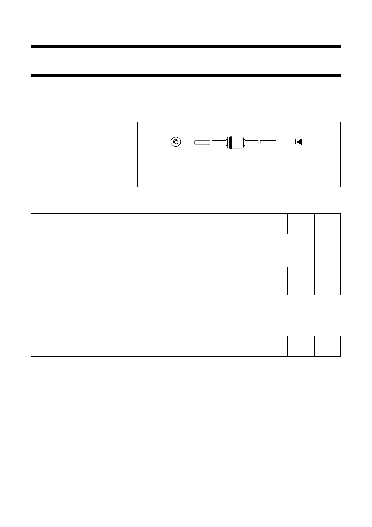
handbook, halfpage
ka
MAM241
Fig.1 Simplified outline (SOD66; DO-41) and symbol.
LIMITING VALUES
In accordance with the Absolute Maximum Rating System (IEC 134).
SYMBOL PARAMETER CONDITIONS MIN. MAX. UNIT
I
F
I
ZM
continuous forward current − 500 mA
working current see Table
“Per type”
I
ZSM
non-repetitive peak reverse current see Table
“Per type”
P
tot
T
stg
T
j
total power dissipation T
=50°C − 1000 mW
amb
storage temperature −65 +200 °C
junction temperature −65 +200 °C
ELECTRICAL CHARACTERISTICS
Total series
T
=25°C; unless otherwise specified.
j
SYMBOL PARAMETER CONDITIONS MIN. MAX. UNIT
V
F
forward voltage IF= 200 mA; see Fig.3 − 1.2 V
1996 Apr 26 2
Page 3
1996 Apr 26 3
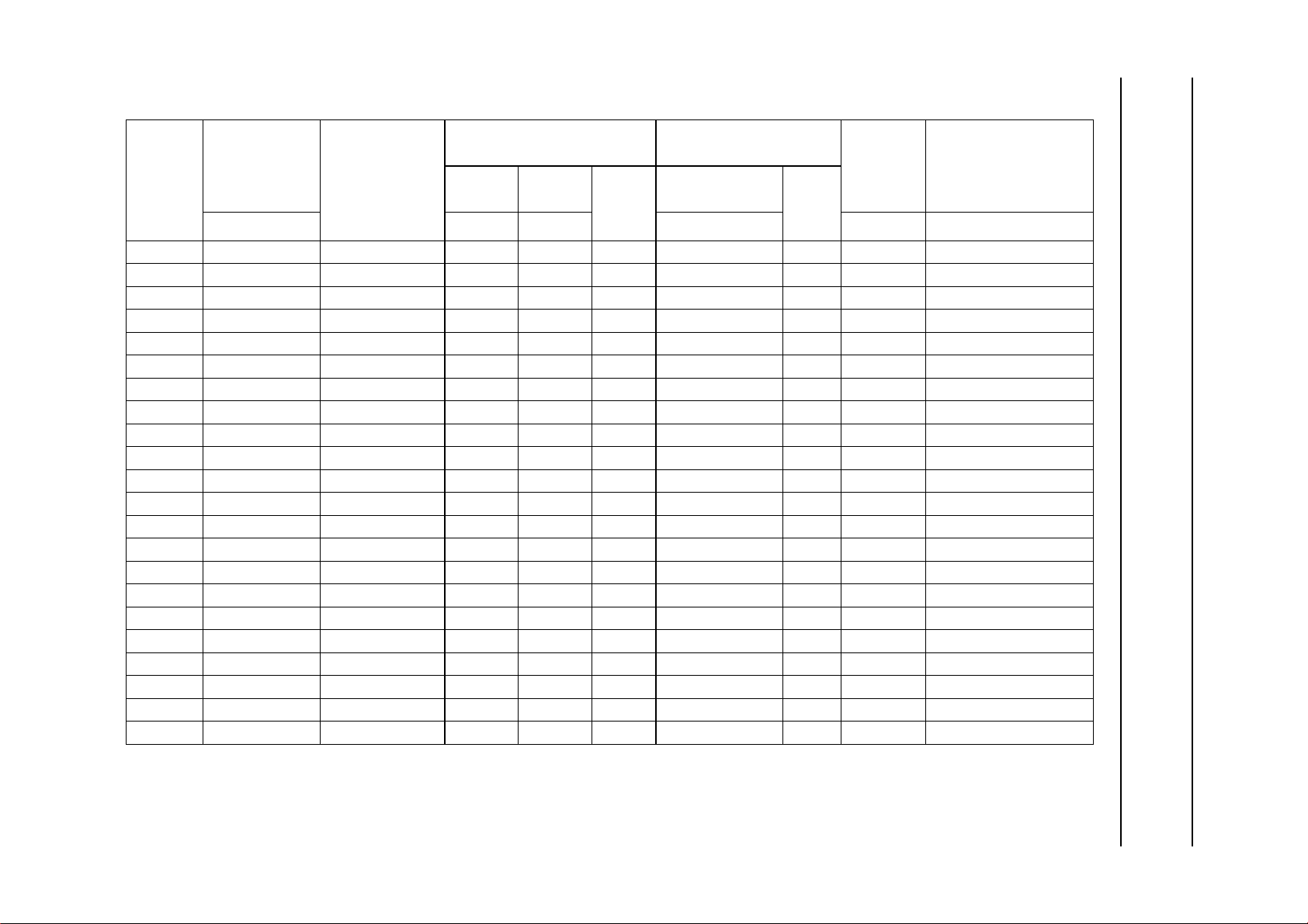
Per type
=25°C; unless otherwise specified.
T
j
Philips Semiconductors Product specification
Voltage regulator diodes 1N4728A to 1N4749A
TYPE No.
WORKING
VOLTAGE
(1)
(V)
V
Z
at I
Ztest
NOM.
TEST CURRENT
(mA)
I
Ztest
DIFFERENTIAL
RESISTANCE
r
dif
at I
(Ω)
Ztest
r
dif
at I
(Ω)
Z
I
Z
(mA)
MAX. MAX. MAX. MAX. MAX.
REVERSE CURRENT
at REVERSE VOLTAGE
I
(µA)
R
(V)
V
R
WORKING
CURRENT
IZM (mA)
NON-REPETITIVE
PEAK REVERSE
1N4728A 3.3 76 10 400 1 100 1 276 1380
1N4729A 3.6 69 10 400 1 100 1 252 1260
1N4730A 3.9 64 9 400 1 50 1 234 1190
1N4731A 4.3 58 9 400 1 10 1 217 1070
1N4732A 4.7 53 8 500 1 10 1 193 970
1N4733A 5.1 49 7 550 1 10 1 178 890
1N4734A 5.6 45 5 600 1 10 2 162 810
1N4735A 6.2 41 2 700 1 10 3 146 730
1N4736A 6.8 37 3.5 700 1 10 4 133 660
1N4737A 7.5 34 4 700 0.5 10 5 121 605
1N4738A 8.2 31 4.5 700 0.5 10 6 110 550
1N4739A 9.1 28 5 700 0.5 10 7 100 500
1N4740A 10 25 7 700 0.25 10 7.6 91 454
1N4741A 11 23 8 700 0.25 5 8.4 83 414
1N4742A 12 21 9 700 0.25 5 9.1 76 380
1N4743A 13 19 10 700 0.25 5 9.9 69 344
1N4744A 15 17 14 700 0.25 5 11.4 61 304
1N4745A 16 15.5 16 700 0.25 5 12.2 57 285
1N4746A 18 14 20 750 0.25 5 13.7 50 250
1N4747A 20 12.5 22 750 0.25 5 15.2 45 225
1N4748A 22 11.5 23 750 0.25 5 16.7 41 205
1N4749A 24 10.5 25 750 0.25 5 18.2 38 190
CURRENT
I
(mA)
ZSM
(2)
Notes
1. V
is measured with device at thermal equilibrium while held in clips at 10 mm from body in still air at 25 °C.
Z
2. Half square wave or equivalent sinewave pulse1⁄
second duration superimposed on I
120
Ztest
.
Page 4

Philips Semiconductors Product specification
Voltage regulator diodes 1N4728A to 1N4749A
THERMAL CHARACTERISTICS
SYMBOL PARAMETER CONDITIONS VALUE UNIT
R
th j-tp
thermal resistance from junction to tie-point lead length 4 mm; see Fig.2 110 K/W
1996 Apr 26 4
Page 5

Philips Semiconductors Product specification
Voltage regulator diodes 1N4728A to 1N4749A
GRAPHICAL DATA
3
10
handbook, full pagewidth
R
th j-tp
(K/W)
2
10
10
1
−1
10
δ = 1
0.75
0.50
0.33
0.20
0.10
0.05
0.02
0.01
0
11010
2103
Fig.2 Thermal resistance from junction to tie-point; lead length 4 mm.
MBG928
t
p
T
4
10
δ =
tp (ms)
t
p
T
5
10
300
handbook, halfpage
I
F
(mA)
200
100
0
0 1.0
(1) Tj= 200°C; typical values.
(2) Tj=25°C; typical values.
0.5
Fig.3 Forward current as a function of
forward voltage.
MBG925
(1) (2)
VF (V)
1996 Apr 26 5
Page 6
Philips Semiconductors Product specification
Voltage regulator diodes 1N4728A to 1N4749A
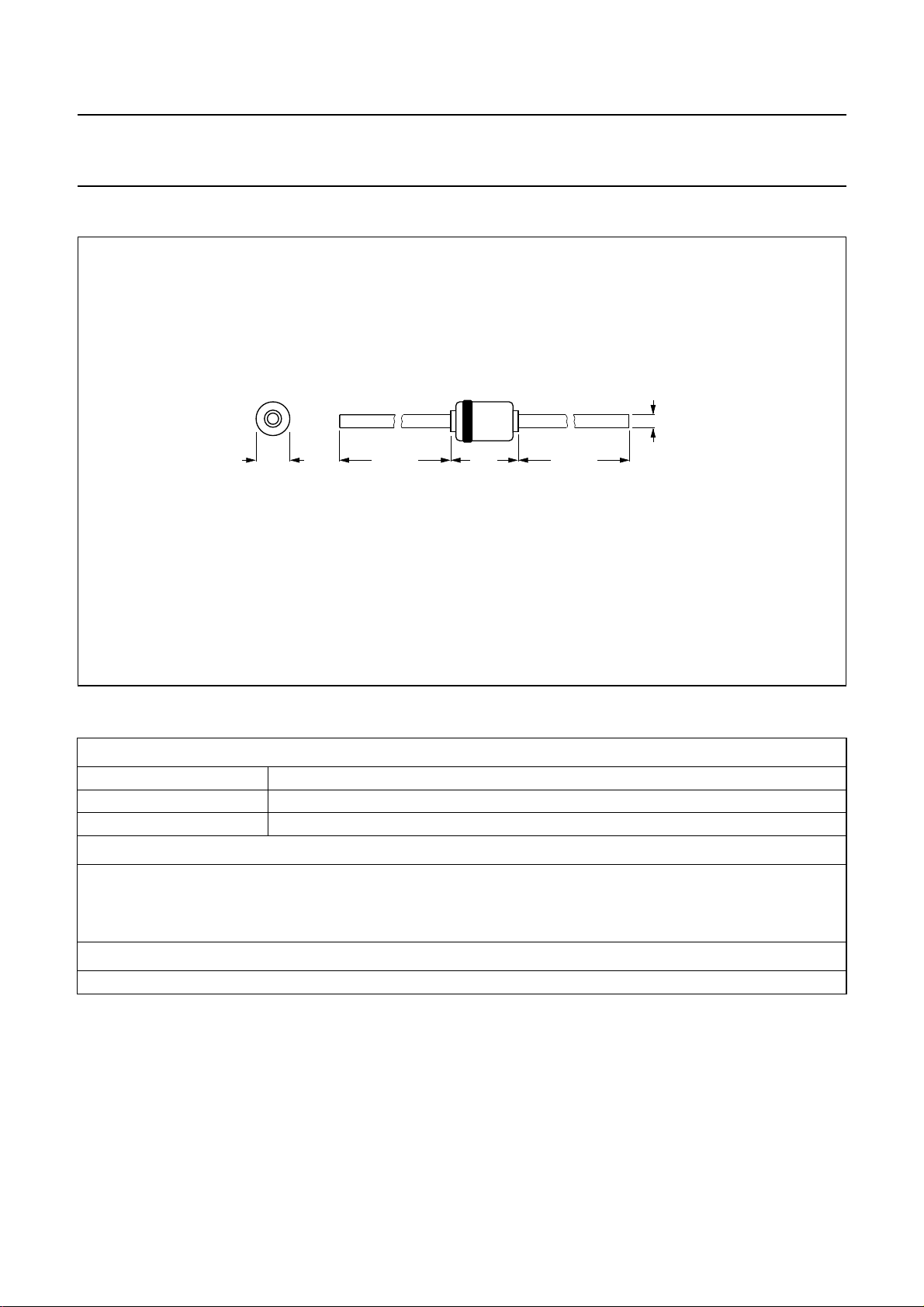
PACKAGE OUTLINE
handbook, full pagewidth
Dimensions in mm.
2.6
max
k
28 min 28 min
4.8
max
a
0.81
max
MBC894
Fig.4 SOD66 (DO-41).
DEFINITIONS
Data sheet status
Objective specification This data sheet contains target or goal specifications for product development.
Preliminary specification This data sheet contains preliminary data; supplementary data may be published later.
Product specification This data sheet contains final product specifications.
Limiting values
Limiting values given are in accordance with the Absolute Maximum Rating System (IEC 134). Stress above one or
more of the limiting values may cause permanent damage to the device. These are stress ratings only and operation
of the device at these or at any other conditions above those given in the Characteristics sections of the specification
is not implied. Exposure to limiting values for extended periods may affect device reliability.
Application information
Where application information is given, it is advisory and does not form part of the specification.
LIFE SUPPORT APPLICATIONS
These products are not designed for use in life support appliances, devices, or systems where malfunction of these
products can reasonably be expected to result in personal injury. Philips customers using or selling these products for
use in such applications do so at their own risk and agree to fully indemnify Philips for any damages resulting from such
improper use or sale.
1996 Apr 26 6
 Loading...