

Page 1
1N2804 thru 1N2846B and
557 thru
1N4
1N4564B
50 Watt Zener Diodes
These high power 50 W Zener diodes represented by the JEDEC registered
SCOTTSDALE DIVISION
DESCRIPTION
1N2804 thru 1N2846B and 1N4557 thru 1N4564B series provide voltage
regulation in a selection over a 3.9 V to 200 V broad range of voltages. They
may be operated up to 50 W with adequate mounting and heat sinking with
their low thermal resistance. These Zeners are also available in JAN,
JANTX, JANTXV military qualifications. Microsemi also offers numerous
other Zener products to meet higher and lower power applications.
IMPORTANT: For the most current data, consult MICROSEMI’s website: http://www.microsemi.com
• JEDEC registered 1N2804 thru 1N2846B and
1N4557 thru 1N4564B
• Internal solder bond construction
• Hermetically sealed (welded)
• Zener Voltage 3.9V to 200V.
• Also available in JAN, JANTX, and JANTXV
qualifications per MIL-PRF-19500/114 by adding the
JAN, JANTX, or JANTXV prefixes to part numbers
for desired level of screening; (e.g.
JANTX1N2804B, etc.
• Standard polarity is anode to case
• Reverse polarity with cathode to case by designating
R suffix in part number, e.g. 1N2804RB, etc.
• Consult factory for surface mount equivalents
FEATURES
• Regulates voltage over a broad operating
current and temperature range
• Standard voltage tolerances are +/- 5% with B
• Consult factory for +/-2% or +/-1% with a C or D
• Reverse polarity available
• Nonsensitive to ESD per MIL-STD-750 Method
• Inherently radiation hard as described in
APPLICATIONS / BENEFITS
suffix, +/-10% with an A suffix, and +/-20% with no
suffix
suffix respectively
1020
Microsemi MicroNote 050
• Junction Temperatures: -65
• Storage Temperatures: -65
• DC Power Dissipation: 50 watts at T
• Power Derating: 0.5W/
• Forward Voltage @ 10 A: 1.5 Volts
• THERMAL RESISTANCE: 2.0
junction to base (1.5
• Solder temperatures: 260
MAXIMUM RATINGS
o
C above 75oC
o
C/W typical)
o
C to +175oC
o
C to +200oC
< 75 oC
C
o
C/W maximum
o
C for 10 s (max)
MECHANICAL AND PACKAGING
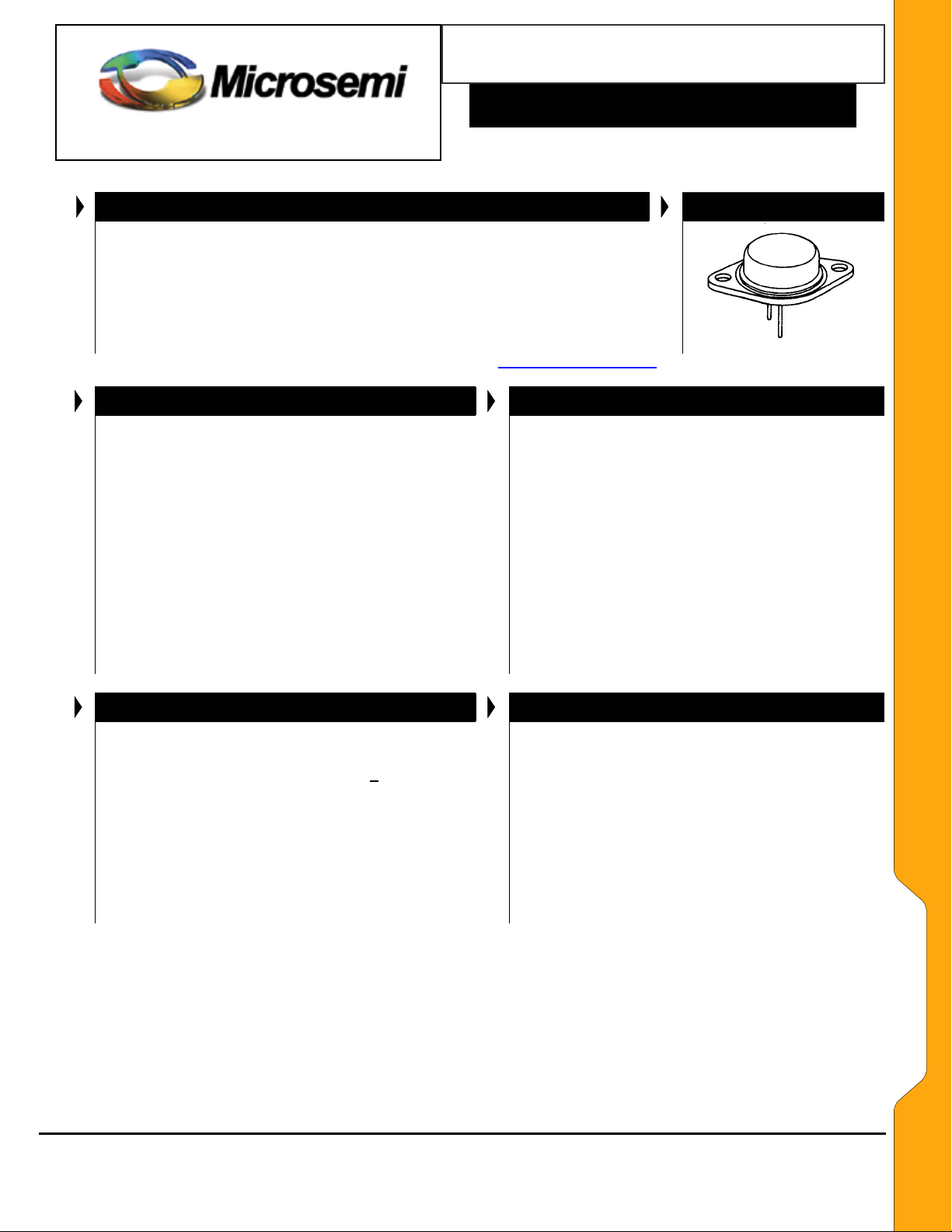
• CASE: Industry Standard TO-3 (TO-204AD),
hermetically sealed, 0.052 inch diameter pins.
• FINISH: All external surfaces are corrosion
resistant and terminal solderable.
• POLARITY: Standard Polarity units are connected
anode to case. Reverse polarity (cathode to case)
is indicated by Suffix R in part number
• WEIGHT: 15 grams.
• MOUNTING HARDWARE: Consult factory for
optional insulator and sheet metal screws
• See package dimensions on last page
Copyright 2003
11-12-2003 REV A
8700 E. Thomas Rd. PO Box 1390, Scottsdale, AZ 85252 USA, (480) 941-6300, Fax: (480) 947-1503
Microsemi
Scottsdale Division
APPEARANCE
TO-3
(TO-204AD)
Page 1
WWW.
Microsemi
. COM
1N2804 - 46B &
1N4557B – 64B
Page 2
1N2804 thru 1N2846B and
557 thru
1N4
1N4564B
SCOTTSDALE DIVISION
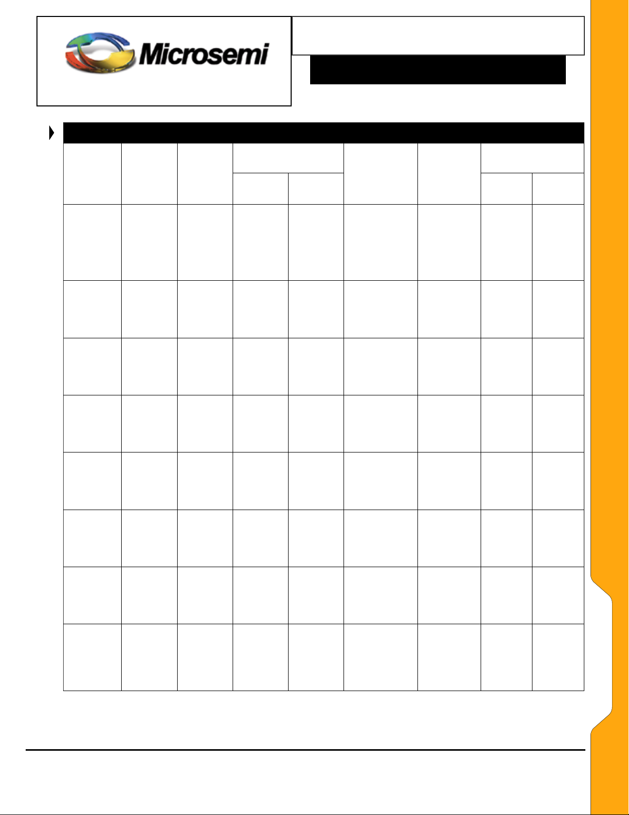
ELECTRICAL CHARACTERISTICS @ 25oC
*
JEDEC
TYPE NO.
(Note 1)
†1N4557B
†1N4558B
†1N4559B
†1N4560B
†1N4561B
†1N4562B
1N4563B
1N4564B
†1N2804B
†1N2805B
†1N2806B
†1N2807B
†1N2808B
†1N2809B
†1N2810B
†1N2811B
1N2812B
†1N2813B
†1N2814B
1N2815B
†1N2816B
1N2817B
†1N2818B
†1N2819B
†1N2820B
1N2821B
†1N2822B
†1N2823B
†1N2824B
†1N2825B
†1N2826B
†1N2827B
1N2828B
†1N2829B
1N2830B
†1N2831B
†1N2832B
†1N2833B
†1N2834B
†1N2835B
†1N2836B
†1N2837B
†1N2838B
1N2839B
†1N2840B
†1N2841B
†1N2842B
†1N2843B
†1N2844B
†1N2845B
†1N2846B
NOMINAL
ZENER
VOLTAGE
VZ @ IZT
(Note 2)
Volts
3.9
4.3
4.7
5.1
5.6
6.2
6.8
7.5
6.8
7.5
8.2
9.1
10
11
12
13
14
15
16
17
18
19
20
22
24
25
27
30
33
36
39
43
45
47
50
51
56
62
68
75
82
91
100
105
110
120
130
150
160
180
200
ZENER
TEST
CURRENT
(IZT)
mA
3200
2900
2650
2450
2250
2000
1850
1650
1850
1700
1500
1370
1200
1100
1000
960
890
830
780
740
700
660
630
570
520
500
460
420
380
350
320
290
280
270
250
245
220
200
180
170
150
140
120
120
110
100
95
85
80
68
65
*JEDEC Registered Data. **Not JEDEC Data.
†Have JAN, JANTX and JANTXV Qualifications to MIL-S-19500/114.
S
Copyright 2003
11-12-2003 REV A
ee further notes on following page
8700 E. Thomas Rd. PO Box 1390, Scottsdale, AZ 85252 USA, (480) 941-6300, Fax: (480) 947-1503
MAX. ZENER
IMPEDANCE
(Note 3)
ZZT @ IZT
OHMS
0.16
0.16
0.12
0.12
0.12
0.14
0.16
0.24
0.2
0.3
0.4
0.5
0.6
0.8
1.0
1.1
1.2
1.4
1.6
1.8
2.0
2.2
2.4
2.5
2.6
2.7
2.8
3.0
3.2
3.5
4.0
4.5
4.5
5.0
5.0
5.2
6
7
8
9
11
15
20
25
30
40
50
75
80
90
100
Microsemi
Scottsdale Division
Z
ZK
5mA
OHMS
400
500
600
650
900
1000
200
100
100
100
100
100
110
120
140
150
160
180
200
210
220
240
275
400
450
525
600
70
70
70
70
80
80
80
80
80
80
80
80
80
80
80
80
80
90
90
90
90
90
90
90
@
(IZK)
MAX. DC ZENER
CURRENT
(
IZM
Case Temp.
50 Watt Zener Diodes
MAXIMUM LEAKAGE
µA V
150
150
100
150
100
@ 75oC
(Note 4)
mA
11,900
10,650
9,700
8,900
8,100
7,300
6,650
6,050
7,400
6,600
5,800
5,300
4,800
4,300
4,000
3,700
3,400
3,100
2,950
2,750
2,550
2,450
2,350
2,100
1,950
1,850
1,650
1,550
1,450
1,300
1,175
1,075
1,030
980
935
925
825
735
670
600
550
470
450
430
410
375
345
300
285
250
220
TYPICAL
ZENER
VOLTAGE
Temp. Coeff.
α
VZ
o
%/
C
-0.046
-0.033
-0.015
+/-0.010
+0.03
+0.049
+0.053
+0.057
.040
.045
.048
.050
.055
.060
.065
.065
.070
.070
.070
.075
.075
.075
.075
.080
.080
.080
.085
.085
.085
.085
.090
.090
.090
.090
.090
.090
.090
.090
.090
.090
.090
.090
.090
.095
.095
.095
.095
.095
.095
.095
.100
CURRENT**
IR @ VR
20
20
20
10
10
50
25
25
10
10
10
10
10
10
10
10
10
10
10
10
10
10
10
10
10
10
10
10
10
10
10
10
10
10
10
10
10
10
10
10
10
10
10
10
10
10
0.5
0.5
1
1
1
2
2
3
4.5
5
5.4
6.1
6.7
8.4
9.1
9.9
10.6
11.4
12.2
13.0
13.7
14.4
15.2
16.7
18.2
19
20.6
22.8
25.1
27.4
29.7
32.7
34.2
35.8
38
38.8
42.6
47.1
51.7
56
62.2
69.2
76
79.8
83.6
91.2
98.8
114.0
121.6
136.8
152.0
Page 2
WWW.
Microsemi
. COM
1N2804 - 46B &
1N4557B – 64B
Page 3

1N2804 thru 1N2846B and
557 thru
1N4
1N4564B
SCOTTSDALE DIVISION
NOTES:
1. The JEDEC type numbers shown (B suffix) have a +/- 5% tolerance on nominal zener voltage. The suffix A is used to identify +/-10%
tolerance; no suffix indicates +/-20% tolerance. If tighter tolerance is required, consult factory. Standard polarity units have the anode
connected to the case. Reverse polarity (cathode-to-case) units are available and are indicated by suffix R in the part number.
2. Zener Voltage (V
so that at nominal voltages the dissipation is a constant 12.5 watts. This results in a nominal junction temperature rise of 18.75oC .
3. The zener impedance is derived from the 60 cycle ac voltage, which results when an ac current having an rms value equal to 10% of the dc
zener current (IZT or IZK) is superimposed on IZT or IZK. Zener impedance is measured at 2 points to ensure a sharp knee on the breakdown
curve and to eliminate unstable units. A curve showing the variation of zener impedance vs. zener current for six representative types is
shown in Figure 3. Also see MicroNote 202 for further information.
4. The values of I
above VZT that results from zener impedance and the increase in junction temperature as power dissipation approaches 50 watts. In the
case of individual diodes, I
) is measured with junction in thermal equilibrium with 30oC base temperature. The test currents (IZT) have been selected
Z
are calculated for a +/-5% tolerance on nominal zener voltage. Allowance has been made for the rise in zener voltage
ZM
is that value of current that results in a dissipation of 50 watts.
ZM
GRAPHS AND CIRCUITS
50 Watt Zener Diodes
Typical circuit connections for anode-to-case and
cathode-to-case polarities (standard and reverse
polarities, respectively).
WWW.
Microsemi
. COM
Rated Power Dissipation - Watts
Case Temperature
FIGURE 2
o
C
POWER DERATING CURVE
1N2804 - 46B &
1N4557B – 64B
FIGURE GROUP 3
TYPICAL ZENER IMPEDANCE vs. ZENER CURRENT FOR TYPES SHOWN
Copyright 2003
11-12-2003 REV A
8700 E. Thomas Rd. PO Box 1390, Scottsdale, AZ 85252 USA, (480) 941-6300, Fax: (480) 947-1503
Microsemi
Scottsdale Division
Page 3
Page 4

1N2804 thru 1N2846B and
557 thru
1N4
1N4564B
SCOTTSDALE DIVISION
PACKAGE DIMENSIONS
50 Watt Zener Diodes
WWW.
Microsemi
. COM
1N2804 - 46B &
1N4557B – 64B
Copyright 2003
11-12-2003 REV A
Microsemi
Scottsdale Division
8700 E. Thomas Rd. PO Box 1390, Scottsdale, AZ 85252 USA, (480) 941-6300, Fax: (480) 947-1503
Page 4
 Loading...