

Page 1
RECTRON
Back
SEMICONDUCTOR
TECHNICAL SPECIFICA TION
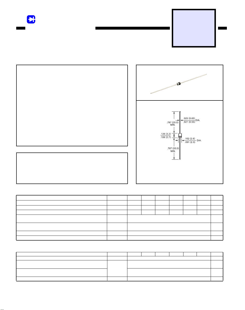
FAST RECOVERY RECTIFIER
VOLTAGE RANGE 1000 to 1800 Volts CURRENT 1.0 Ampere
FEATURES
* Fast switching
* Low leakage
* Low forward voltage drop
* High current capability
* High currenf surge
* High reliability
MECHANICAL DATA
* Case: Molded plastic
* Epoxy: UL 94V-O rate flame retardant
* Lead: MIL-STD-202E method 208C guaranteed
* Mounting position: Any
* Weight: 0.19 gram
1F10
THRU
1F18
R-1
MAXIMUM RATINGS AND ELECTRICAL CHARACTERISTICS
Ratings at 25 oC ambient temperature unless otherwise specified.
Single phase, half wave, 60 Hz, resistive or inductive load.
For capacitive load, derate current by 20%.
MAXIMUM RATINGS
Maximum Recurrent Peak Reverse Voltage
Maximum RMS Voltage
Maximum DC Blocking Voltage
Maximum Average Forward Rectified Current
at TA = 25oC
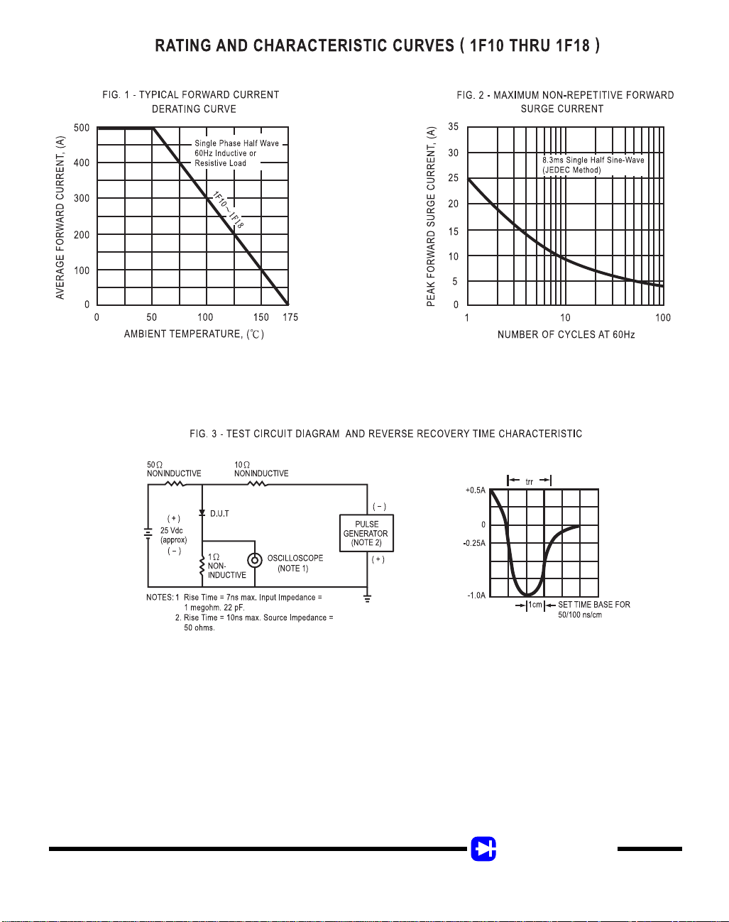
Peak Forward Surge Current 8.3 ms single half sine-wave
superimposed on rated load (JEDEC method)
Typical Junction Capacitance (Note 2)
Operating and Storage Temperature Range
ELECTRICAL CHARACTERISTICS
Maximum Instantaneous Forward Voltage at 0.5A DC
Maximum DC Reverse Current
at Rated DC Blocking Voltage TA = 25oC
Maximum Full Load Reverse Current Full Cycle Average,
.375” (9.5mm) lead length at TL = 55oC
Maximum Reverse Recovery Time (Note 1)
NOTES : 1. Reverse Recovery Test Conditions: IF = 0.5A, IR = 1.0A, IRR = 0.25A
2. Measured at 1 MHZ and applied reverse voltage of 4.0 volts
(At TA = 25oC unless otherwise noted)
RATINGS
(At TA = 25oC unless otherwise noted)
CHARACTERISTICS
SYMBOL
V
RRM
V
RMS
V
DC
I
O
I
FSM
C
J
TJ, T
STG
SYMBOL
V
F
I
R
trr
Dimensions in inches and (millimeters)
1F10
1F12
1F14
1000
1200
840
1200
1400
980
1400
25
15
-65 to + 150
1.8
5.0
100
300
700
1000
1F10 1F12 1F14 1F15 1F16 1F18 UNITS
1F15
1500
1050
1500
1F16
1600
1120
1600
1F18
1800
1260
1800
UNITS
Volts
Volts
Volts
Amps0.5
Amps
pF
0
C
Volts
uAmps
uAmps
nSec
1998-8
Page 2
RECTRON
 Loading...