

Page 1
PRODUCT INFORMATION
Europe: Tel (46) 8 58 02 45 00 Fax (46) 8 58 02 01 10
Tel (44) 1291 436180 Fax (44) 1291 436771
America: Tel 1-800-96MITEL Fax (613) 592-6909
Asia: Tel (65) 293 5312 Fax (65) 293 8527
PRODUCT INFORMATION
11865.11 1994-09-20
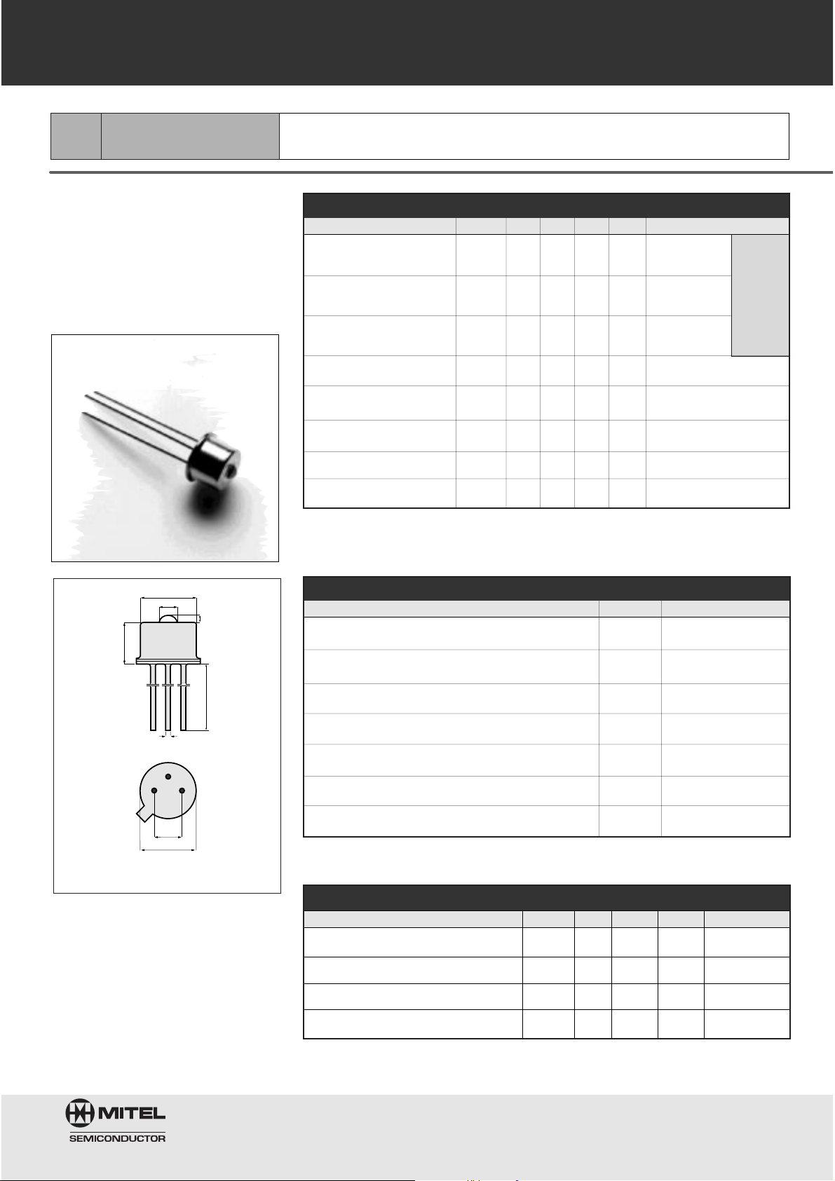
860nm
1A194
High-Performance LED
Datacom, General Purpose
0.6
14
Ø1.5
Ø4.7
3.7
0.4
5.4
2.5
CASE
ANODE
CATHODE
BOTTOM VIEW
The diode chip is isolated from the case.
TO-46 Package With Lens
All dimensions in mm
This device is designed for Ethernet
and general applications and offers
an excellent price/performance ratio
for cost-effective solutions. Its double-lens optical system results in
optimum coupling of power into the
fiber.
Fiber:
50/125mm
Graded
Index
NA=0.20
Optical and Electrical Characteristics
(25°C Case Temperature)
Thermal Characteristics
Absolute Maximum Ratings
Note 1: Measured at the exit of 100 meters of fiber.
PARAMETER SYMBOL MIN. TYP. MAX. UNIT TEST CONDITION
Fiber-Coupled Power P
fiber
25 45 mW IF=60 mA
(Fig.1,2,&3) (Table1) (Note 1)
Rise and Fall Time tr,t
f
57nsI
F
=60 mA
(10-90%) (no bias)
Bandwidth f
c
70 MHz IF=60 mA
(3dBel)
Peak Wavelength l
p
840 860 880 nm IF=60 mA
Spectral Width (FWHM) Dl 50 nm IF=60 mA
Forward Voltage (Fig.5) V
F
1.7 1.9 V IF=60 mA
Reverse Current I
R
20 mA VR=1V
Capacitance C 250 pF VR=0V, f=1MHz
PARAMETER SYMBOL MIN. TYP. MAX. UNIT
Thermal Resistance- Infinite Heat Sink R
thjc
200 8C/W
Thermal Resistance- No Heat Sink R
thja
500 8C/W
Temperature Coefficient- Optical Power dP/dT
j
-0.5 %/8C
Temperature Coefficient-Wavelength dl/dT
j
0.3 nm/8C
PARAMETER SYMBOL LIMIT
Storage Temperature T
stg
-55 to +1258C
Operating Temperature (derating: Fig.4) Top -55 to +1258C
Electrical Power Dissipation(derating: Fig.4) P
tot
160 mW
Continuous Forward Current (f<10 kHz) I
F
80 mA
Peak Forward Current (duty cycle<50%, f>1 MHz) I
FRM
130 mA
Reverse Voltage V
R
1.5 V
Soldering Temperature (2mm from the case for 10 sec) T
sld
2608C
Page 2
860nm
1A194
High-Performance LED
Core Diameter/Cladding Diameter
Numerical Aperture
50/125mm 62.5/125mm 100/140mm 200/230 m m
0.20 0.275 0.29 0.37
Table 1
Typical Fiber-Coupled Power
45mW 95 mW 210mW 440mW
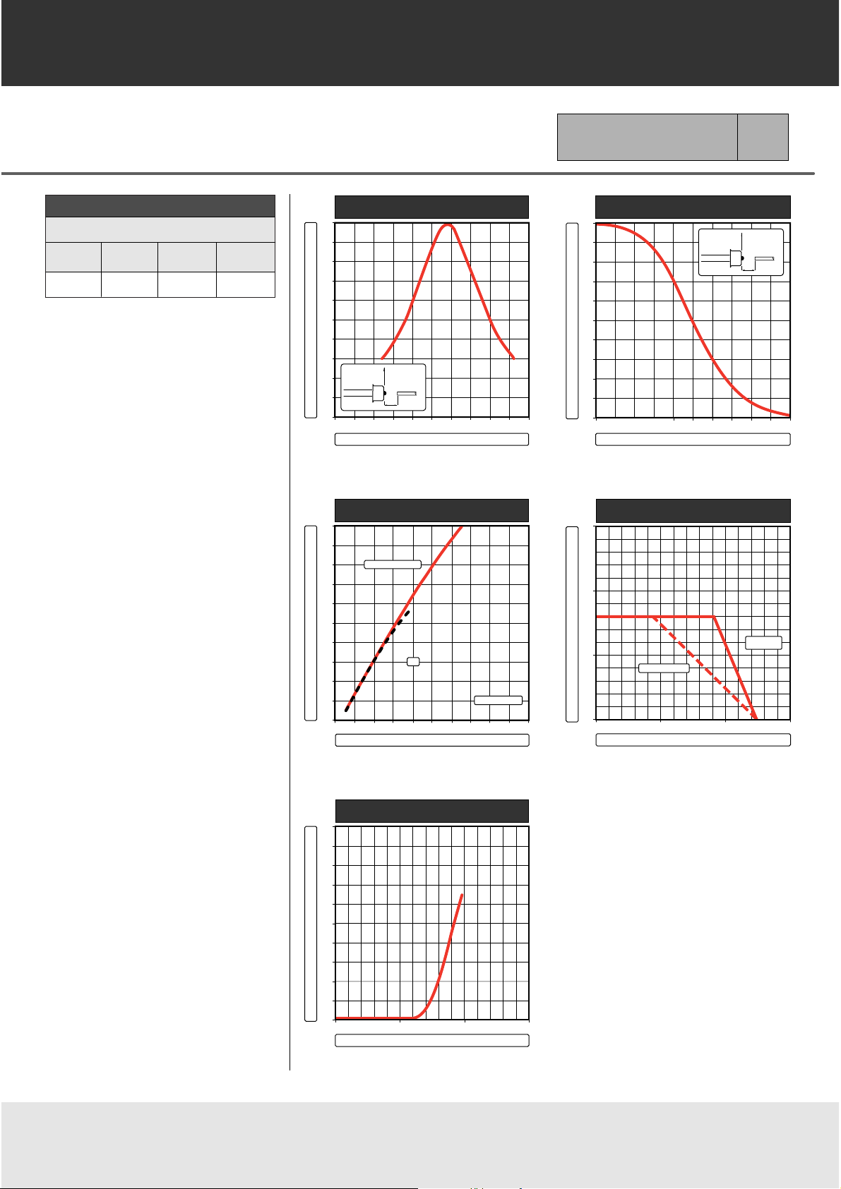
z - AXIAL DISPLACEMENT OF FIBER
0
20
40
60
80
100
%
0.5
1.0 1.5
2.0
2.5
3.0
mm
RELATIVE FIBER-COUPLED POWER
r
r = opt.
Øc = 50 µm
z
FIGURE 1
r - RADIAL DISPLACEMENT OF FIBER
0
20
40
60
80
100
%
0
20 40
60
80
100
m
RELATIVE FIBER-COUPLED POWER
r
z = opt.
Øc = 50 µm
z
FIGURE 2
FORWARD CURRENT
0
20
40
60
80
100
%
0
40 80
120
160
200 mA
RELATIVE FIBER-COUPLED POWER
50% DUTY CYCLE
DC
HEAT SINKED
FIGURE 3
FORWARD VOLTAGE
FORWARD CURRENT
mA
200
100
0
0
1 2
3
V
FIGURE 5
mW
300
200
100
0
0 50 100
150
¡C
NO HEAT SINK
OPERATING TEMPERATURE
MAX. ELECTRICAL POWER DISSIPATION
FIGURE 4
INFINITE
HEAT SINK
Page 3
5.6000
3.3000
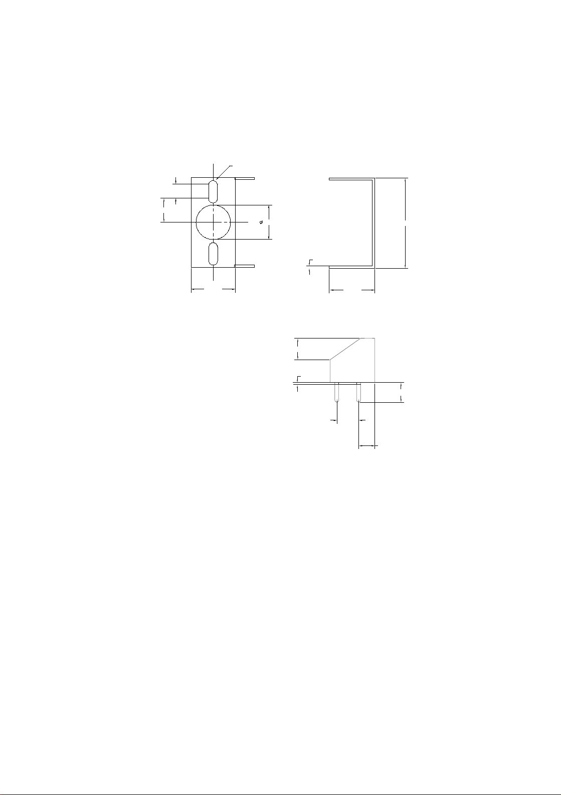
Clip for SC-2A
R 1.00
80,000
0.5000
20.8200
10,2500
10.3000
4.9500
0.5000
4.5000
5.0800
3.6450
Page 4

Clip for Pigtail-3A
0.50
10.70
10.25
10.30
4.95
0.50
4.50
0.85
5.08
3.65
Page 5

PRODUCT INFORMATION
Europe: Tel (46) 8 58 02 45 00 Fax (46) 8 58 02 01 10
Tel (44) 1291 436180 Fax (44) 1291 436771
America: Tel 1-800-96MITEL Fax (613) 592-6909
Asia: Tel (65) 293 5312 Fax (65) 293 8527
103326 1994-09-20
ST-2A
Package
Emitter or Detector in ST®Package
Mitel emitters and detectors can be
provided in this low-profile ST
®
package. The device is electrically
isolated from the ST
®
receptacle to
facilitate electrical connection. And
optimum fiber-coupled power or
responsivity is ensured by active
alignment against the fiber.
Mechanical Outline of Diode in ST-2A Housing
(ST is a registered trademark of AT&T)
All Dimensions in mm
*The fiber-coupled power/responsivity is guaranteed to meet the LED/PIN data sheet - provided a ferrule meeting this specification is used.
Absolute Maximum Ratings
Thermal Characteristics
Note 2: Add R
thjc
for emitter or detector to estimate the total thermal resistance.
Note 1: Temperature range can be extended to -55° to +125°C on request.
12.7
MARKING SIDE
SLOT SIDE
9.5
7.89
2-56 UNC - 2B
max.0.5
min.12 20.1
3.9
5.4
7.6
3/8"-32 UNEF
0.006
FIBER
END
Ø2.5
Ø2.502
+0.01
0
+0
-0.004
MATING FERRULE*
(not included)
PARAMETER SYMBOL LIMIT
Operating & Storage Temperature T
stg
, T
op
-40 to +858 C
ST-2A (Note 1)
PARAMETER SYMBOL MIN. TYP. MAX. UNIT
Thermal Resistance- Infinite Heat Sink R
thcc
40 8C/W
(Note 2)
Thermal Resistance- No Heat Sink R
thca
200 8C/W
(Note 2)
Thermal Resistance - On PC Board Rthca 80 8C/W
(Note 2)
Page 6

PRODUCT INFORMATION
Europe: Tel (46) 8 58 02 45 00 Fax (46) 8 58 02 01 10
Tel (44) 1291 436180 Fax (44) 1291 436771
America: Tel 1-800-96MITEL Fax (613) 592-6909
Asia: Tel (65) 293 5312 Fax (65) 293 8527
SMA-2A
Package
Emitter or Detector in SMA Package
103325 1994-09-20
Mitel emitters and detectors can be
provided in this low-profile SMA
package. The device is electrically
isolated from the SMA receptacle to
facilitate electrical connection. And
optimum fiber-coupled power or
responsivity is ensured by active
alignment against the fiber.
MARKING SIDE
9.5
12.7
max.0.5
2-56 UNC - 2B
3.9
5.7
15.2
min.12
7.2
1/4"-36UNS
Ø3.176
+0.01
0
9.8 ± 0.03
FIBER
END
0.006
Ø3.174
+0
-0.004
MATING FERRULE*
(not included)
Mechanical Outline of Diode in SMA-2A Housing
All Dimensions in mm
*
The fiber-coupled power/responsivity is guaranteed to meet the LED/PIN data sheet - provided a ferrule meeting this specification is used.
Absolute Maximum Ratings
Thermal Characteristics
Note 2: Add
R
thjc
for emitter or detector to estimate the total thermal resistance.
Note 1: Temperature range can be extended to -55° to +125°C on request.
PARAMETER SYMBOL MIN. TYP. MAX. UNIT
Thermal Resistance- Infinite Heat Sink R
thcc
40 8C/W
(Note 2)
Thermal Resistance- No Heat Sink R
thca
200 8C/W
(Note 2)
Thermal Resistance - On PC Board Rthca 80 8C/W
(Note 2)
PARAMETER SYMBOL LIMIT
Operating & Storage Temperature
SMA-2A (Note 1)
T
stg
, T
op
-40 to +858 C
Page 7

PRODUCT INFORMATION
Europe: Tel (46) 8 58 02 45 00 Fax (46) 8 58 02 01 10
Tel (44) 1291 436180 Fax (44) 1291 436771
America: Tel 1-800-96MITEL Fax (613) 592-6909
Asia: Tel (65) 293 5312 Fax (65) 293 8527
105967 1994-09-20
Ø2.3
Ø7.5
MARKING / SLOT SIDE
22
8.9
1.4 x 4
18
min. 12
12
2.5
7.95
0.006
FIBER
END
Ø2.5
+0
-0.004
MATING FERRULE*
(not included)
13
18
Mechanical Outline of Diode in SC-2A Housing
All Dimensions in mm * The fiber-coupled power/responsivity is guaranteed to meet the LED/PIN data sheet - provided a ferrule meeting this specification is used.
Mitel emitters and detectors can be
provided in this low-profile SC package. The device is electrically isolated from the SC receptacle to facilitate electrical connection. And optimum fiber-coupled po wer or responsivity is ensured by active alignment
against the fiber..
Absolute Maximum Ratings
Thermal Characteristics
Note 1: Add
R
thjc
for emitter or detector to estimate the total thermal resistance.
PARAMETER SYMBOL MIN. TYP. MAX. UNIT
Thermal Resistance- Infinite Heat Sink R
thcc
40 8C/W
(Note 1)
Thermal Resistance- No Heat Sink R
thca
200 8C/W
(Note 1)
Thermal Resistance - On PC Board Rthca 125 8C/W
(Note 1)
PARAMETER SYMBOL LIMIT
Operating & Storage Temperature T
stg
, T
op
-40 to +858 C
SC-2A
Package
Emitter or Detector in SC Package
Page 8

PRODUCT INFORMATION
Europe: Tel (46) 8 58 02 45 00 Fax (46) 8 58 02 01 10
Tel (44) 1291 436180 Fax (44) 1291 436771
America: Tel 1-800-96MITEL Fax (613) 592-6909
Asia: Tel (65) 293 5312 Fax (65) 293 8527
105429 1997-07-03
Mitel emitters and detectors can be
provided in this pigtail package with
a wide selection of fiber types. The
device is electrically isolated from
the pigtail receptacle to facilitate
electrical connection. And optimum
fiber-coupled power or responsivity
is ensured by active alignment
against the fiber. A special design
maximizes the return loss for detectors in this package.
Note 3: Add
R
thjc
for LED to estimate the total thermal resistance.
Absolute Maximum Ratings
PARAMETER SYMBOL LIMIT
Operating & Storage Temperature
(Note 1 & 2)
T
stg
, T
op
-40 to +858C
Ø 6
min.12
MARKING
13
Ø6.00
Mechanical Outline of Diode in PIGTAIL-3A Housing
Note 1: Temperature range can be extended to -55/+125
8C on request.
Note 2: Temperature range may be limited by the specification of the fiber.
Thermal Characteristics
All Dimensions in mm
Optical Characteristics
PARAMETER SYMBOL MIN. TYP. MAX. UNIT
Thermal Resistance- Infinite Heat Sink R
thcc
25 8C/W
(Note 3)
Thermal Resistance- No Heat Sink R
thca
250 8C/W
(Note 3)
Thermal Resistance- On PC-Board R
thca
120 8C/W
(Note 3)
PARAMETER SYMBOL MIN. TYP. MAX. UNIT
Return Loss 10/125mm fiber RL 40 55 dB
(PIN only)
Pigtail-3A
Package
Emitter or Detector in Pigtail Package
Page 9

PRODUCT INFORMATION
Europe: Tel (46) 8 58 02 45 00 Fax (46) 8 58 02 01 10
Tel (44) 1291 436180 Fax (44) 1291 436771
America: Tel 1-800-96MITEL Fax (613) 592-6909
Asia: Tel (65) 293 5312 Fax (65) 293 8527
105515 1994-09-20
FC-2A
Package
Emitter or Detector in FC Package
19
Ø 2.2
MARKING/ SLOT SIDE
13.4
9.2
M8x0.75 Thread
Ø 2.5
5.50
2.0
5.6min.12
7.95
0.006
FIBER
END
Ø2.5
+0
-0.004
max. 0.5
08
MATING FERRULE*
(not included)
Mitel emitters and detectors can be
provided in this low-profile FC package. The device is electrically isolated from the FC receptacle to facilitate electrical connection. And optimum fiber-coupled power or responsivity is ensured by active alignment
against the fiber.
Mechanical Outline of Diode in FC-2A Housing
Absolute Maximum Ratings
Thermal Characteristics
Note 2: Add
R
thjc
for emitter or detector to estimate the total thermal resistance.
All Dimensions in mm
* The fiber-coupled power/responsivity is guaranteed to meet the LED/PIN data sheet - provided a ferrule meeting this specification is used.
Note 1: Temperature range can be extended to -55° to +125°C on request.
PARAMETER SYMBOL MIN. TYP. MAX. UNIT
Thermal Resistance- Infinite Heat Sink R
thcc
40 8C/W
(Note 2)
Thermal Resistance- No Heat Sink R
thca
200 8C/W
(Note 2)
Thermal Resistance - On PC Board Rthca 80 8C/W
(Note 2)
PARAMETER SYMBOL LIMIT
Operating & Storage Temperature T
stg
, T
op
-40 to +858 C
FC-2A (Note 1)
Page 10

http://www.mitelsemi.com
World Headquarters - Canada
Tel: +1 (613) 592 2122
Fax: +1 (613) 592 6909
North America Asia/Pacific Europe, Middle East,
Tel: +1 (770) 486 0194 Tel: +65 333 6193 and Africa (EMEA)
Fax: +1 (770) 631 8213 Fax: +65 333 6192 Tel: +44 (0) 1793 518528
Fax: +44 (0) 1793 518581
Information relating to products and services furnished herein by Mitel Corporation or its subsidiaries (collectively “Mitel”) is believed to be reliable. However, Mitel assumes no
liability for errors that may appear in this publication, or for liability otherwise arising from the application or use of any such information, product or service or for any infringement of
patents or other intellectual property rights owned by third parties which may result from such application or use. Neither the supply of such information or purchase of product or
service conveys any license, either express or implied, under patents or other intellectual property rights owned by Mitel or licensed from third parties by Mitel, whatsoever.
Purchasers of products are also hereby notified that the use of product in certain ways or in combination with Mitel, or non-Mitel furnished goods or services may infringe patents or
other intellectual property rights owned by Mitel.
This publication is issued to provide information only and (unless agreed by Mitel in writing) may not be used, applied or reproduced for any purpose nor form part of any order or
contract nor to be regarded as a representation relating to the products or services concerned. The products, their specifications, services and other information appearing in this
publication are subject to change by Mitel without notice. No warranty or guarantee express or implied is made regarding the capability, performance or suitability of any product or
service. Information concerning possible methods of use is provided as a guide only and does not constitute any guarantee that such methods of use will be satisfactory in a specific
piece of equipment. It is the user’s responsibility to fully determine the performance and suitability of any equipment using such information and to ensure that any publication or
data used is up to date and has not been superseded. Manufacturing does not necessarily include testing of all functions or parameters. These products are not suitable for use in
any medical products whose failure to perform may result in significant injury or death to the user. All products and materials are sold and services provided subject to Mitel’s
conditions of sale which are available on request.
M Mitel (design) and ST-BUS are registered trademarks of MITEL Cor poration
Mitel Semiconductor is an ISO 9001 Registered Company
Copyright 1999 MITEL Corporation
All Rights Reserved
Printed in CANADA
TECHNICAL DOCUMENTATION - NOT FOR RESALE
 Loading...