

Datasheet 130HF80PV, 130HF80PSV, 130HF80PBV, 130HF80MV, 130HF80MSV Datasheet (International Rectifier)
...Page 1
Features
High current carrying capability
High surge current capability
Types up to 1200V V
RRM
Stud cathode and stud anode version
Standard JEDEC types
Diffused junction
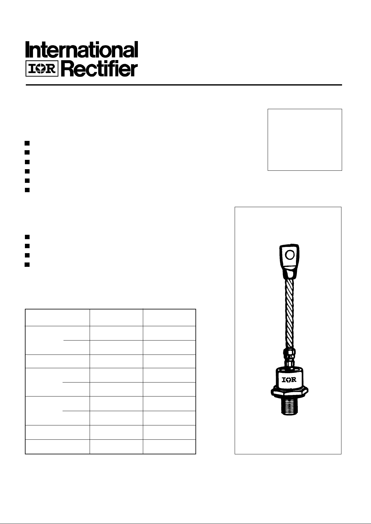
case style
DO-205AC (DO-30)
I
F(AV)
130 A
@ T
C
125 °C
I
F(RMS)
200 A
I
FSM
@ 50Hz 2000 A
@ 60Hz 2100 A
I2t@
50Hz 20 KA2s
@ 60Hz 18 KA2s
V
RRM
range 400 to 1200 V
T
J
-40 to 180 °C
Parameters 130HF(R) Units
Major Ratings and Characteristics
T ypical Applications
Battery chargers
Converters
Power supplies
Machine tool controls
130HF(R) SERIES
Stud V ersionSTANDARD RECOVERY DIODES
130 A
Bulletin I2019/A
Page 2
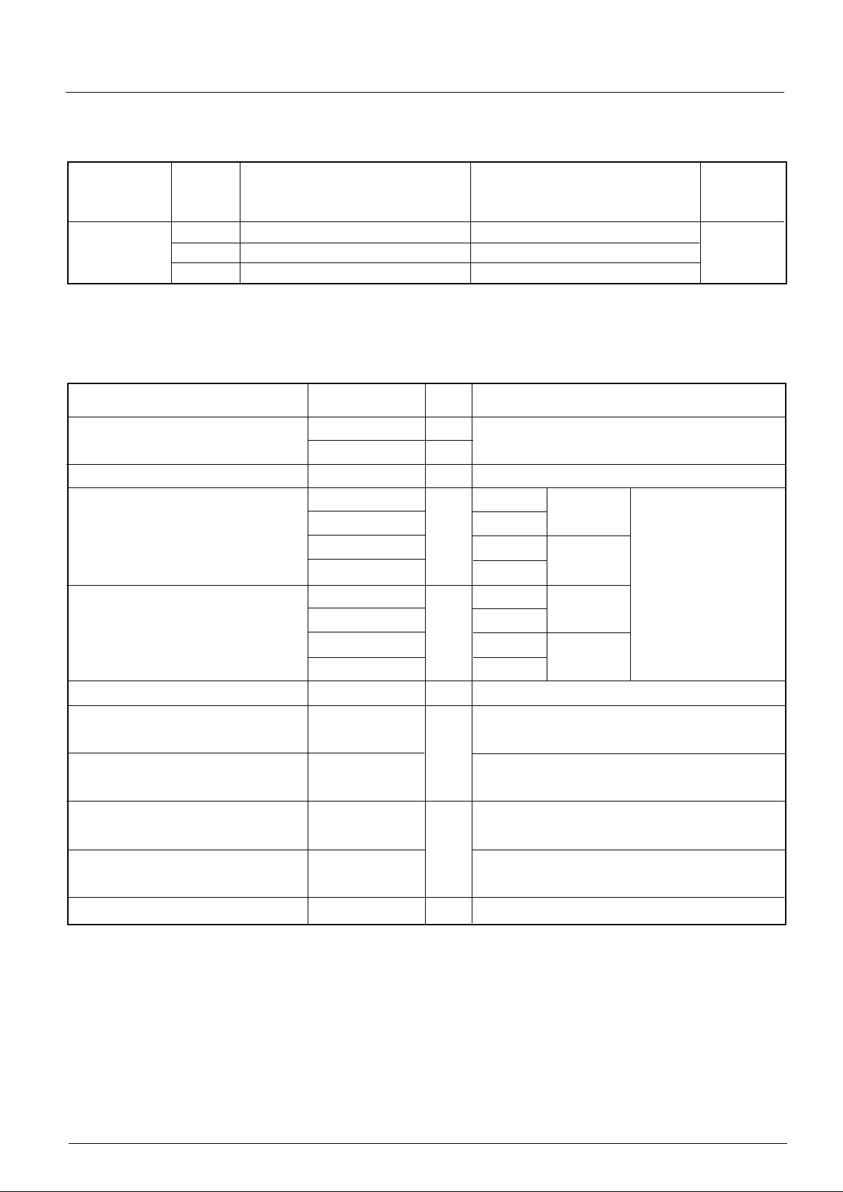
130HF(R) Series
Voltage V
RRM
, maximum repetitive V
RSM
, maximum non- I
RRM
max.
Type number Code peak reverse voltage repetitive peak rev. voltage @ 180°C
VVmA
40 400 500
130HF(R) 80 800 900 15
120 1200 1300
ELECTRICAL SPECIFICATIONS
Voltage Ratings
I
F(AV)
Max. average forward current 130 A 180° conduction, half sine wave
@ Case temperature 125 °C
I
F(RMS)
Max. RMS forward current 200 A DC @ 115°C case temperature
I
FSM
Max. peak, one-cycle forward, 2000 t = 10ms No voltage
non-repetitive surge current 2100 t = 8.3ms reapplied
1680 t = 10ms 100% V
RRM
1760 t = 8.3ms reapplied Sinusoidal half wave,
I
2
t Maximum I2t for fusing 20 t = 10ms No voltage Initial TJ = TJ max
18 t = 8.3ms reapplied
14 t = 10ms 100% V
RRM
13 t = 8.3ms reapplied
I
2
√t Maximum I2√t for fusing 200 KA2√s t = 0.1 to 10ms, no voltage reapplied
V
F(TO)1
Low level value of threshold
voltage
V
F(TO)2
High level value of threshold
voltage
r
f1
Low level value of forward
slope resistance
r
f2
High level value of forward
slope resistance
V
FM
Max. forward voltage drop 1.5 V Ipk= 500A, TJ = 25 °C
Parameter 130HF(R) Units Conditions
Forward Conduction
0.76 (16.7% x π x I
F(AV)
< I < π x I
F(AV)
), TJ = TJ max.
0.95 (I > π x I
F(AV)
), TJ = TJ max.
1.41 (16.7% x π x I
F(AV)
< I < π x I
F(AV)
), TJ = TJ max.
1.02 (I > π x I
F(AV)
), TJ = TJ max.
KA2s
A
V
mΩ
Page 3

D-5
130HF(R) Series
Parameter 130HF(R) Units Conditions
°C
T
J
Max. operating temperature range -40 to 180
T
stg
Max. storage temperature range -55 to 180
R
thJC
Max. thermal resistance, junction to case 0.3 DC operation
R
thCS
Max. thermal resistance, case to heatsink 0.08 Mounting surface, smooth, flat and greased
T Max. allowed mounting torque +0 -20% 11 Not lubricated threads
10 Lubricated threads
wt Approximate weight 120 g
Case style DO-205AC(DO-30) See Outline Table
K/W
Nm
Thermal and Mechanical Specification
∆R
thJC
Conduction
(The following table shows the increment of thermal resistence R
thJC
when devices operate at different conduction angles than DC)
180° 0.052 0.042 T
J
= TJ max.
120° 0.064 0.070
90° 0.083 0.090 K/ W
60° 0.117 0.120
30° 0.177 0.180
Conduction angle Sinusoidal conduction Rectangular conduction Units Conditions
Ordering Information Table
130 HF R 120 P B V
1 234 56
Device Code
1 - Essential Part Number
2 - Diode
3 - None = Stud Normal Polarity (Cathode to Stud)
R = Stud Reverse Polarity (Anode to Stud)
4 - Voltage code: Code x 10 = V
RRM
(See Voltage Ratings table)
5 - P = Stud base DO-205AC(DO-30) 1/2" 20UNF-2A
M= Stud base DO-205AC(DO-30) M12x1.75
6 - B = Flag top terminals (for Cathode/ Anode Leads)
S= Isolated lead with silicone sleeve
(Red = Reverse Polarity; Blue = Normal Polarity)
None = Not isolated lead
7 - V = Glass-metal seal
7
Page 4

130HF(R) Series
Outline Table
DO-205AC (DO-30) Flag
All dimensions in millimeters (inches)
GLASS-METAL SEAL
MAX.
21 (0.82)
MAX.
16.5 (0.65)
6.5 (0.26) MIN.
DIA. 8.5 (0.33) NOM.
157 (6.18)
55 (2.16) MIN.
DIA. 23.5 (0.93) MAX.
24 (0.94)
MAX.
SW 27
* FOR METRIC DEVICE: M12 X 1.75
170 (6.69)
1/2"-20UNF-2A*
12.5 (0.49)
MAX.
C.S. 16mm
2.6 (0.10) MAX.
2
35 (1.38)
MAX.
(0.015 s.i.)
MAX.
GLASS-METAL SEAL
MAX.
21 (0.82)
MAX.
DIA. 23.5 (0.93) MAX.
24 (0.94)
12.5 (0.49)
16.5 (0.65)
5.6 (0.22)
DIA. 5.54 (0.22)
2.4 (0.09)
27 (1.06)
41 (1.61) MAX.
9.5 (0.37)
*FOR METRIC DEVICE. M12 X 1.75
36.5 (1.44)
1/2"-20UNF-2A*
Conforms to JEDEC DO-205AC (DO-30)
All dimensions in millimeters (inches)
Page 5

D-7
130HF(R) Series
110
120
130
140
150
160
170
180
0 20 40 60 80 100 120 140
30°
60°
90°
120°
180°
Average For w ard Current (A )
Conduction Angle
130HF(R ) Series
R (DC) = 0.3 K/W
M axim um Allowable Case Temperature ( °C)
thJC
110
120
130
140
150
160
170
180
0 40 80 120 160 200 240
DC
30°
60°
90°
120°
180°
Conduction P er i od
130HF(R ) S eries
R (DC) = 0 .3 K /W
thJC
M axim um Allowable Case Tem perature ( °C )
Average For w ard Current (A)
Fig. 1 - Current Ratings Characteristics Fig. 2 - Current Ratings Characteristics
0 20 40 60 80 100 120 140 160 180
M axim um Allowable Am bient Temperature (°C)
R
=
0
.
1
K
/
W
-
D
e
l
t
a
R
t
h
S
A
0
.
2
K
/
W
0
.
3
K
/
W
0
.
4
K
/
W
0
.
5
K
/
W
0
.
6
K
/
W
0
.
8
K
/
W
1
K
/
W
1
.
2
K
/
W
0
20
40
60
80
100
120
140
160
180
0 20 40 60 8 0 100 120 140
180°
120°
90°
60°
30°
RMS Limit
Conduction Angle
Maximum Average For w ard Pow e r Loss (W )
Average Forward C urrent (A )
130HF(R) Series
T = 180°C
J
0 20 40 60 80 100 120 140 160 180
Maximum Allowable Amb ient Temperat ure (°C )
R
=
0
.
1
K
/
W
-
D
e
l
t
a
R
t
h
S
A
0
.
2
K
/
W
0
.
3
K
/
W
0
.
4
K
/
W
0
.
6
K
/
W
0
.
8
K
/
W
1
K
/W
1
.
2
K
/
W
0
.5
K/ W
0
40
80
120
160
200
240
0 40 80 120 160 200 240
DC
180°
120°
90°
60°
30°
RM S Limit
Conduction Per iod
M axim um Average Forward Power Loss (W)
Average For w ard Current (A )
130HF(R) Series
T = 180 °C
J
Fig. 3 - Forward Power Loss Characteristics
Fig. 4 - Forward Power Loss Characteristics
Page 6

130HF(R) Series
400
600
800
1000
1200
1400
1600
1800
110100
Number Of Equal Amplitude Half Cycle Current Pulses (N)
Peak Half Sine Wave Forward Curre nt (A)
Initial T = 180 °C
@ 60 H z 0.0083 s
@ 50 H z 0.0100 s
J
130HF(R) Series
At Any Rated Load Condition And With
Rate d V A pplied Following Su rge.
RRM
400
600
800
1000
1200
1400
1600
1800
2000
0.01 0.1 1
Pul se Trai n Dur ation (s)
Peak Half Sine Wave Forward Current (A)
Initial T = 180 °C
No Volt age Reapplied
Rated V Reapplied
RRM
Maxi mu m N on Repetitive Sur ge Cur rent
J
130HF(R) Series
Versus Puls e Train Du r ation.
Fig. 5 - Maximum Non-Repetitive Surge Current Fig. 6 - Maximum Non-Repetitive Surge Current
10
100
1000
10000
012345
T = 25°C
J
In stant aneous For ward Voltage ( V)
Instantaneous For ward Cur r ent (A)
130HF(R) Series
T = 180°C
J
Fig. 7 - Forward Voltage Drop Characteristics
Fig. 8 - Thermal Impedance Z
thJC
Characteristics
0.01
0.1
1
0.001 0.01 0.1 1 10
Square Wave P ulse Du ration (s)
thJC
Transient Thermal Impeda n ce Z (K/W)
Steady State Value :
R = 0. 3 K/W
(DC O per ation)
thJC
130HF(R) Series
 Loading...