

Page 1
0912-45
45 Watts, 50 Volts, Pulsed
Avionics 960 - 1215 MHz
GENERAL DESCRIPTION
The 0912-45 is a COMMON BASE bipolar transistor. It is designed for
pulsed systems in the frequency band 960-1215 MHz. The device has gold
thin-film metallization for proven highest MTTF. The transistor includes
input prematch for broadband capacity. Low thermal resistance package
reduces junction temperature, extends life.
ABSOLUTE MAXIMUM RATINGS
Maximum Power Dissipation @ 25 C 225 Watts
Maximum Voltage and Current
BVces Collector to Base Voltage 60 Volts
BVebo Emitter to Base Voltage 4.0 Volts
Ic Collector Current 4.5 Amps
Ma ximum Temperatures
Storage Temperature - 65 to + 150 C
Operating Junction Temperature + 200 C
ELECTRICAL CHARACTERISTICS @ 25 C
o2
o
o
O
CASE OUTLINE
55CX, STYLE 1
SYMBOL CHARACTERISTICS TEST CONDITIONS MIN TYP MAX UNITS
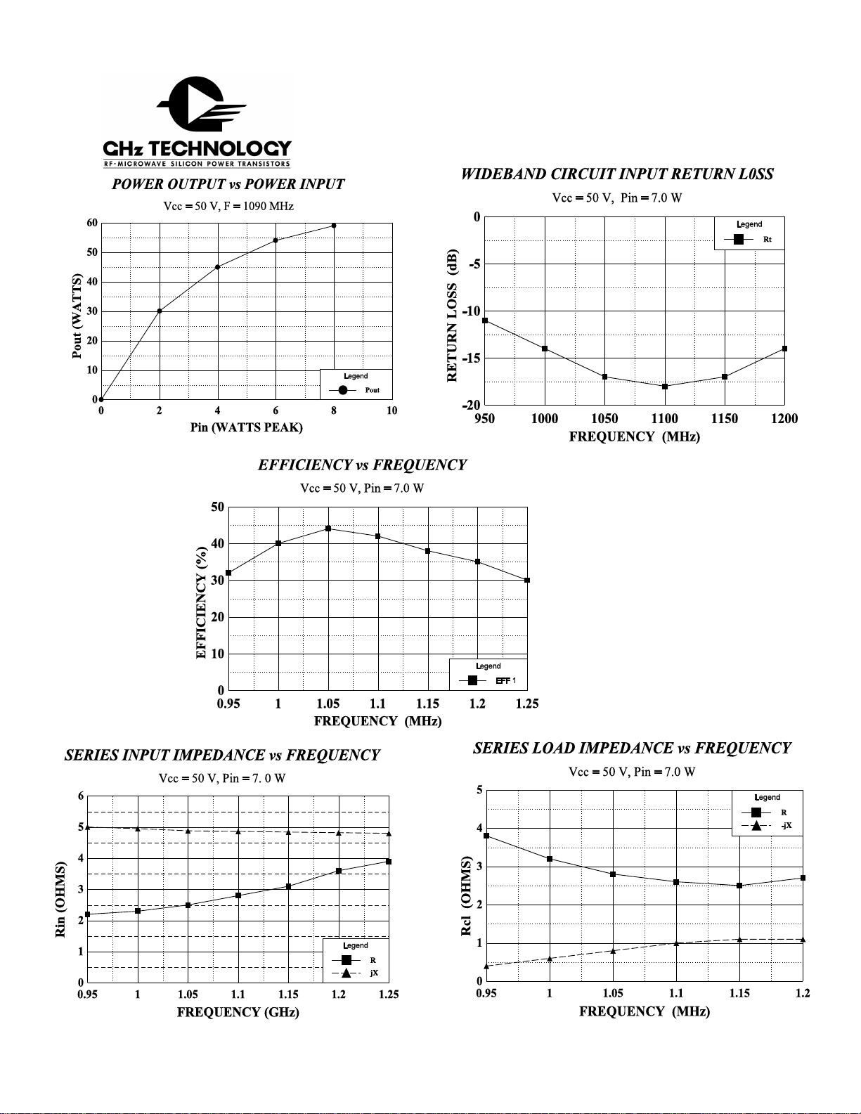
Pout
Pin
2
Pg
2
η
c
VSWR
Power Out
Power Input
Power Gain
2
Collector Efficiency
Load Mismatch Tolerance
F = 960-1215 MHz
Vcc = 50 Volts
PW = 10 µsec
DF = 1%
F = 1090 MHz
45
8.0 9.0
45
7.0
10:1
Watts
Watts
dB
%
BVebo
BVces
Cob
h
FE
2
jc
θ
Emitter to Base Breakdown
Collector to Emitter Breakdown
Capacitance Collector to Base
DC - Current Gain
Thermal Resistance
Ie = 25 mA
Ic = 75 mA
Vcb = 50V
Ic = 300 mA, Vce = 5 V
4.0
60
10
20
0.8
Volts
Volts
pF
o
C/W
Note 1: At rated output power and pulse conditions
2: At rated pulse conditions
Initial Issue June, 1994
GHz TECHNOLOGY INC. RESERVES THE RIGHT TO MAKE CHANGES WITHOUT FURTHER NOTICE. GHz RECOMMENDS THAT
BEFORE THE PRODUCT(S) DESCRIBED HEREIN ARE WRITTEN INTO SPECIFICATIONS, OR USED IN CRITICAL APPLICATIONS,
THAT THE PERFORMANCE CHARACTERISTICS BE VERIFIED BY CONTACTING THE FACTORY.
GHz Technology Inc. 3000 Oakmead Village Drive, Santa Clara, CA 95051-0808 Tel. 408 / 986-8031 Fax 408 / 986-8120
Page 2
0912-45
Page 3

0912-45
Input 50 Ohms
Z1
C3
L1
0912-45 BROADBAND CIRCUIT
Z2
C4
Q1
Z3
C1 C2
50 VDC
R1
L2
C7
Z4 Z5
50 Ohm Output
C6
C5
PC Board Material .010" Dielectric Teflon Fiberglass
Z1=50W, .08l, = .027"w X .59"L
Z2=2.7W, .064l, =.80"w X .44"L
Z3=10W, .062l, =.20"w X .443"L
Z4=3.7W, .08l, =.55"w X .55"L
Z5=50W, .075l, =.027"w X .56"L
L1= Inductor #14 wire, 0.7" long
L2= Inductor #18 wire, 1.5" long
August 1996
C1=Capacitor 100 pF "B" (100mil) ATC
C2=Capacitor 68mfd, 75V Electrolytic
C3, C4, C5, C6= Capacitor .35-3.5pF Piston Trimmer
C4=Capacitor 47pF "B" (100mil) ATC
R1= Resistor, 15WK 1/4W
Q1=GHz Transistor 0912-45
All electrical lengths taken at 1.09 GHz
 Loading...