

Page 1
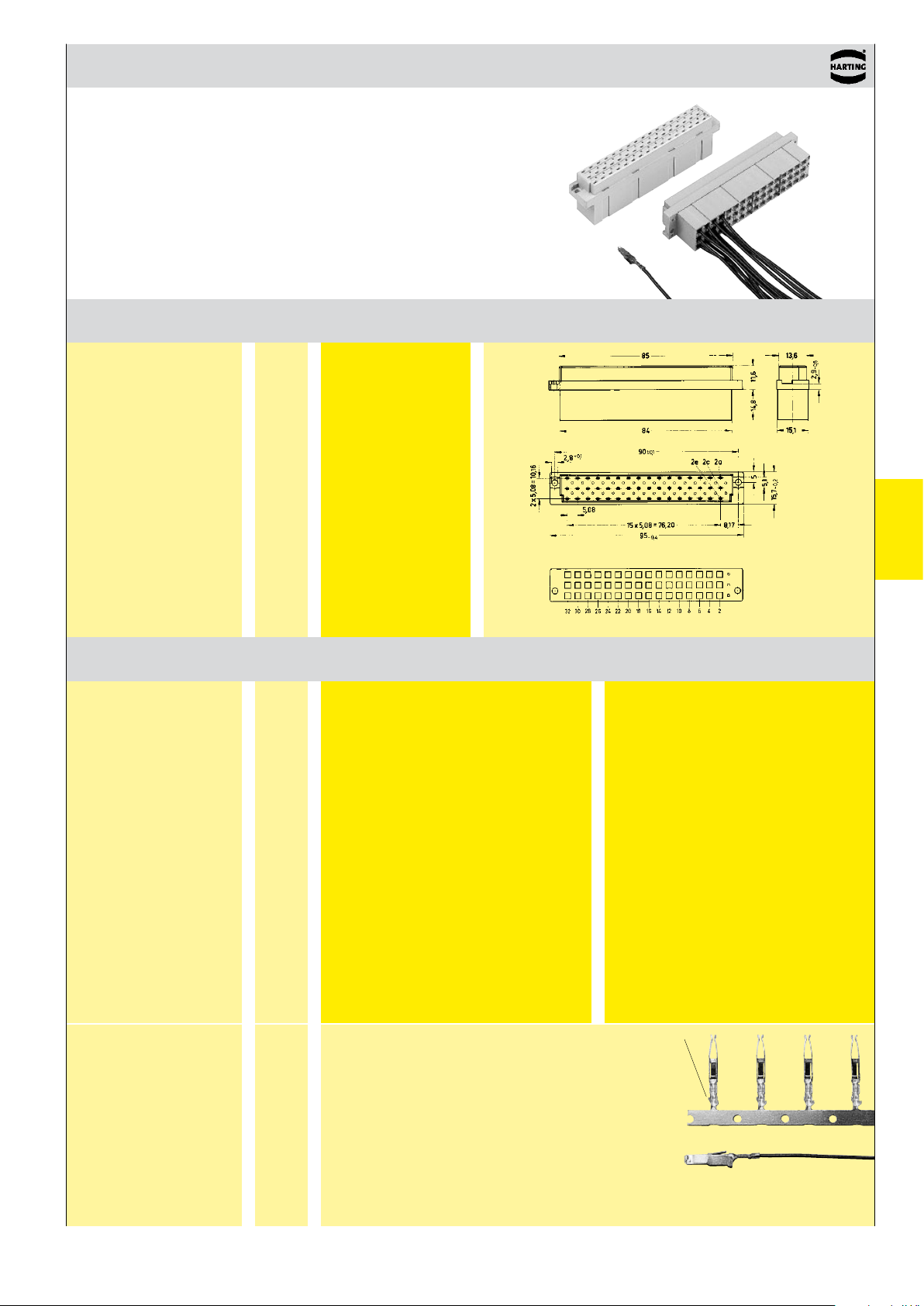
DIN 41 612 · Type E
Number of contacts
max. 48
Female connectors
Number
Identification of contacts Part No. Drawing Dimensions in mm
Female connector
for crimp contacts
Order contacts separately
48 09 05 048 3202
Identification
Identification Wire gauge
Female crimp FC
contacts
Bandoliered contacts
(approx. 2 ,500 pieces)
Bandoliered contacts
(approx. 250 pieces)
Individual contacts
1)
1 09 06 000 6484 09 06 000 6474
2 09 06 000 6481 09 06 000 6471
3 09 06 000 6482 09 06 000 6472
1 09 06 000 7484 09 06 000 7474
2 09 06 000 7481 09 06 000 7471
3 09 06 000 7482 09 06 000 7472
1 09 06 000 8484 09 06 000 8474
2 09 06 000 8481 09 06 000 8471
3 09 06 000 8482 09 06 000 8472
f)
c)
09 05 548 3202
Part No. Performance levels according to IEC 60603-2. Explanation chapter 00
c)
Contact arrangement
Shell housing 09 05 048 0501 see chapter 20
View from termination side
2 1
DIN Power
up to 6 A
Female contacts with
solder lugs
(lockable)
c)
Connectors with coding see chapter 00
f)
Railway classification NFF 16-101, Smoke index: F1,
Flammability class: I2
2)
FC 1
FC 2
FC 3
09 06 000 6420
Wire gauge Insulation ø
mm² AWG mm
1 0.09 - 0.25 28 - 24 0.7 - 1.5
2 0.14 - 0.56 26 - 20 0.8 - 2.0
3 0.5 - 1.5 20 - 16 1.6 - 2.8
3.5 + 0.5 mm of insulation is stripped from the wires
to be crimped
For the fabrication in line with the specification please
use exclusively crimp tools approved by HARTING
(see DIN EN 60 352-2)
Insertion, removal and crimping tools see chapter 30
Identification
Bandoliered
contacts
Individual contacts
1)
Packaging unit 1,000 pieces
2)
Solder contacts must not be used together with shell housing A.
Special contact surface: 2 µm gold.
03
.
17
 Loading...