

Datasheen D316S, D324S User Manual
1

FCC Certifications
This Equipment has been tested and found to comply with the limits for a Class A
digital devi ce, pur suant to part 1 5 of th e FCC Rul es. Th ese li mits a re de signed to
provide reasonable protection against harmful interference when the equipment
is operated in a commercial environment. This equipment generates, uses, and
can radiate radio f requ ency en ergy a nd, if not installed and used in accordance
with the instruction manual, may cause harmful interference to radio
communications.
Operation of this equipment in a residential area is likely to cause harmful
interference in which case the user will be required to correct the interference at
his own expense.
This device complies with Part 15 of the FCC Rules. Operation is subject to the
following two conditions: (1) this device may not cause harmful in terference, and
(2) this device must accept any interference received; including interference that
may cause undesired operation.
CE Mark Warning
This equipment complies with the requirements relating to electromagnetic
compatibility, EN 55022 class A for ITE, the essential protection requirement of
Council Directive 89/336/EEC on the approximation of the laws of the Member
States relating to electromagnetic compatibility.
Company has an on-going policy of upgrading its products and it may be possible
that information in this document is not up-to-date. Please check with your local
distributors for the latest information. No part of this document can be copied or
reproduced in any form without written consent from the company.
Trademarks:
All trade names and trademarks are the properties of their respective companies.
Copyright © 2009, All Rights Reserved.
2

Table of Contents
UNPACKING INFORMATION ....................... 5
INTRODUCTION ............................................. .. 5
ENERAL DESCRIPTION ................................................... 5
G
K
EY FEATURES.............................................................. 5
HE FRONT PANEL ............ ............................................. 6
T
LEDs Definition ....................................................... 6
T
HE REAR PANEL ........................................................... 7
INSTALLATION ................................................. 8
ESKTOP INSTALLATION .................................... .............. 8
D
ACK-MOUNT INSTALLATION ................ ............................. 8
R
NSTALLING NETWORK CABLES........................................... 9
I
FUNCTIONAL DESCRIPTION ..................... 10
LOW CONTROL AND BACK PRESSURE ................ ............... . 10
F
IRROR ....................................... ............................ 10
M
VLAN ..................................................... ................ 10
RUNK (AGGREGATION) ................................ ................ 10
T
Q
UALITY OF SERVICE (QOS) ........................................... 10
MANAGEMENT GUIDE .................................. 11
CCESS THE SWITCH .................................................... 11
A
OMEPAGE ................................................................ 12
H
DMINISTRATOR ......................................... ................ 13
A
Authentication Configuration .................................. 13
System IP configuration ......................................... 13
System ................................................................ 14
3

Load Default Setting ..................................... ........ 14
Firmware Upgrade ................................................ 14
ORT MANAGEMENT .................................................... . 15
P
Port Configuration ..................................... ............ 15
Port Mirroring ....................................................... 16
Bandwidth Control ................................................ 16
Broadcast Storm Control ........................................ 17
VLAN
SETTING .................................................. ........ 18
Group VLAN Setting .............................. .... .... .... ... . 18
Multi to 1 Setting .................................................. 18
RUNK SETTING .......................................................... 19
T
Q
OS SETTING ............................................................ 20
Priority Mode ................................................. ........ 20
Class of Service Configuration .................................... 21
ADDRESS CONFIGURATION ...................................... 21
MAC
C
ONFIGURATION BACKUP/RECOVERY.................................. 22
PRODUCT SPECIFICATIONS ..................... 23
4

Unpacking Information
Thank you for purchasing the D316S 16-Ports/D324S 24-Ports Fast
Ethernet Web Smart Switch. Before you start, please verify that your
package contains the following items:
1. One 16/24-Ports Fast Ethernet Web Smart Switch
2. One power cord
3. Rack-mount brackets and screws (optional)
4. Manual CD
D316S/ D324S Introduction
General Description
Easily managing your LAN, the 16/24-Ports Fast Ethernet Web Smart S witch
provides you 16/24*10/100Mbps ports that allow more efficient
management. With the user-friendly Web-based management interface,
you can easily get the overall information of your LAN.
This device provides sufficient management functions. VLAN reduces the
collisions from widely broadcasting. Port Aggregation enlarges the
bandwidth of backbone connection. QoS is supported to secure the
bandwidth for some bandwidth-demanded applications including VoIP or
videoconference. The 802.3x and backpressure flow control mechanisms
are also supported to ensure t he correctness o f data transmitting. Speed ,
duplex mode auto-detection is also supported for your convenient
installation.
Key Features
16/24 fixed 10/100Mbps Fast Ethernet ports for easy network connecting
application.
Provide 4K MAC address entries and 16/24 groups VLAN table
Support Port Mirror.
Support up to 4 ports and 2 groups port aggregation.
Support QoS for better communication quality.
Support full duplex flow control and half duplex back pressure
Store-and-forward forwarding scheme
Error packet filtering
1.5M bits buffer Memory
Support Web-based management interface.
FCC Class A, CE, VCCI. Meet RoHS.
5
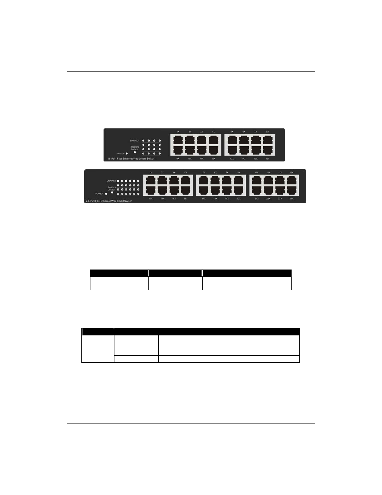
D316S / D324S Front Panel
The front panel consists of LED indicators. Please refer to the following
paragraph for information.
LEDs Definition
LED for the device:
The switch provides a power LED for the device.
LED Status Operation
Power
LED for each port:
LED Status Operation
Green The port is conne cted.
LINK/ACT
Blinking Green
Off No valid link on this port.
Steady Green The switch is powered on
Off The switch is powered off
A valid link is established, and there is data
transmitting/receiving.
Port Operation
The auto-negotiation feature allows those p orts running at one of the
6
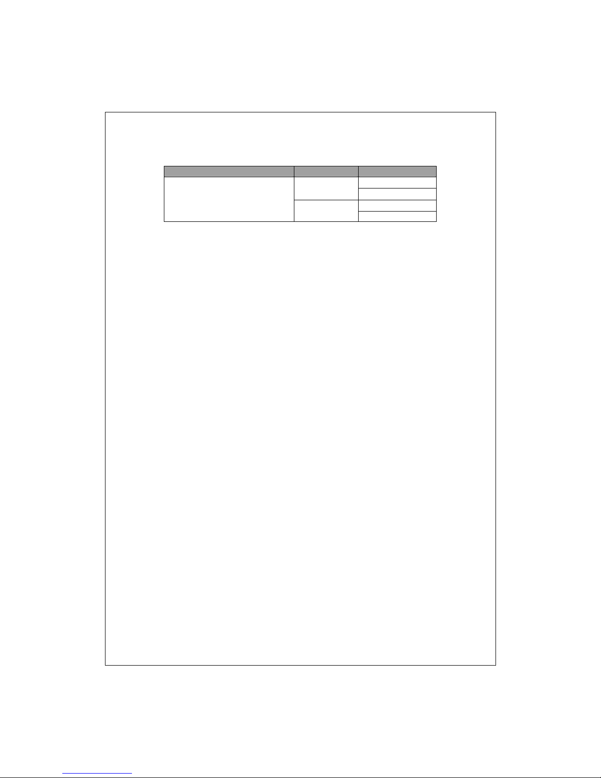
following operation modes:
Media Speed Duplex Mode
10/100Mbps(copper) 10Mbps Full Duplex
Half Duplex
100Mbps
Restore Default Button
You can use this button to reset the switch or restore factory defaul t settings.
To reset the switch, press the button once.
To restore fac tory default settings, press and hold the b utton for three
seconds.
Full Duplex
Half Duplex
The Rear Panel
Power Receptacle
To be compatible with the electric service standards around the world, the
switch is designed to afford the power supply in the range from 100 to
240VAC, 50/60Hz. Please make sure that y our outlet standard to be within
this range.
T o power on the switch, please plug the female end of the power cord firmly
into the receptacle of the switch and the other end into an electric service
outlet. After the power cord installation, please check if the power LED is lit
for a normal power status.
7
 Loading...