

Page 1
1
Page 2

FCC Certifications
This Equipment has been tested and found to comply with the limits for a Class A
digital devi ce, pur suant to part 1 5 of th e FCC Rul es. Th ese li mits a re de signed to
provide reasonable protection against harmful interference when the equipment
is operated in a commercial environment. This equipment generates, uses, and
can radiate radio f requ ency en ergy a nd, if not installed and used in accordance
with the instruction manual, may cause harmful interference to radio
communications.
Operation of this equipment in a residential area is likely to cause harmful
interference in which case the user will be required to correct the interference at
his own expense.
This device complies with Part 15 of the FCC Rules. Operation is subject to the
following two conditions: (1) this device may not cause harmful in terference, and
(2) this device must accept any interference received; including interference that
may cause undesired operation.
CE Mark Warning
This equipment complies with the requirements relating to electromagnetic
compatibility, EN 55022 class A for ITE, the essential protection requirement of
Council Directive 89/336/EEC on the approximation of the laws of the Member
States relating to electromagnetic compatibility.
Company has an on-going policy of upgrading its products and it may be possible
that information in this document is not up-to-date. Please check with your local
distributors for the latest information. No part of this document can be copied or
reproduced in any form without written consent from the company.
Trademarks:
All trade names and trademarks are the properties of their respective companies.
Copyright © 2009, All Rights Reserved.
2
Page 3

Table of Contents
UNPACKING INFORMATION ....................... 5
INTRODUCTION ............................................. .. 5
ENERAL DESCRIPTION ................................................... 5
G
K
EY FEATURES.............................................................. 5
HE FRONT PANEL ............ ............................................. 6
T
LEDs Definition ....................................................... 6
T
HE REAR PANEL ........................................................... 7
INSTALLATION ................................................. 8
ESKTOP INSTALLATION .................................... .............. 8
D
ACK-MOUNT INSTALLATION ................ ............................. 8
R
NSTALLING NETWORK CABLES........................................... 9
I
FUNCTIONAL DESCRIPTION ..................... 10
LOW CONTROL AND BACK PRESSURE ................ ............... . 10
F
IRROR ....................................... ............................ 10
M
VLAN ..................................................... ................ 10
RUNK (AGGREGATION) ................................ ................ 10
T
Q
UALITY OF SERVICE (QOS) ........................................... 10
MANAGEMENT GUIDE .................................. 11
CCESS THE SWITCH .................................................... 11
A
OMEPAGE ................................................................ 12
H
DMINISTRATOR ......................................... ................ 13
A
Authentication Configuration .................................. 13
System IP configuration ......................................... 13
System ................................................................ 14
3
Page 4

Load Default Setting ..................................... ........ 14
Firmware Upgrade ................................................ 14
ORT MANAGEMENT .................................................... . 15
P
Port Configuration ..................................... ............ 15
Port Mirroring ....................................................... 16
Bandwidth Control ................................................ 16
Broadcast Storm Control ........................................ 17
VLAN
SETTING .................................................. ........ 18
Group VLAN Setting .............................. .... .... .... ... . 18
Multi to 1 Setting .................................................. 18
RUNK SETTING .......................................................... 19
T
Q
OS SETTING ............................................................ 20
Priority Mode ................................................. ........ 20
Class of Service Configuration .................................... 21
ADDRESS CONFIGURATION ...................................... 21
MAC
C
ONFIGURATION BACKUP/RECOVERY.................................. 22
PRODUCT SPECIFICATIONS ..................... 23
4
Page 5

Unpacking Information
Thank you for purchasing the D316S 16-Ports/D324S 24-Ports Fast
Ethernet Web Smart Switch. Before you start, please verify that your
package contains the following items:
1. One 16/24-Ports Fast Ethernet Web Smart Switch
2. One power cord
3. Rack-mount brackets and screws (optional)
4. Manual CD
D316S/ D324S Introduction
General Description
Easily managing your LAN, the 16/24-Ports Fast Ethernet Web Smart S witch
provides you 16/24*10/100Mbps ports that allow more efficient
management. With the user-friendly Web-based management interface,
you can easily get the overall information of your LAN.
This device provides sufficient management functions. VLAN reduces the
collisions from widely broadcasting. Port Aggregation enlarges the
bandwidth of backbone connection. QoS is supported to secure the
bandwidth for some bandwidth-demanded applications including VoIP or
videoconference. The 802.3x and backpressure flow control mechanisms
are also supported to ensure t he correctness o f data transmitting. Speed ,
duplex mode auto-detection is also supported for your convenient
installation.
Key Features
16/24 fixed 10/100Mbps Fast Ethernet ports for easy network connecting
application.
Provide 4K MAC address entries and 16/24 groups VLAN table
Support Port Mirror.
Support up to 4 ports and 2 groups port aggregation.
Support QoS for better communication quality.
Support full duplex flow control and half duplex back pressure
Store-and-forward forwarding scheme
Error packet filtering
1.5M bits buffer Memory
Support Web-based management interface.
FCC Class A, CE, VCCI. Meet RoHS.
5
Page 6
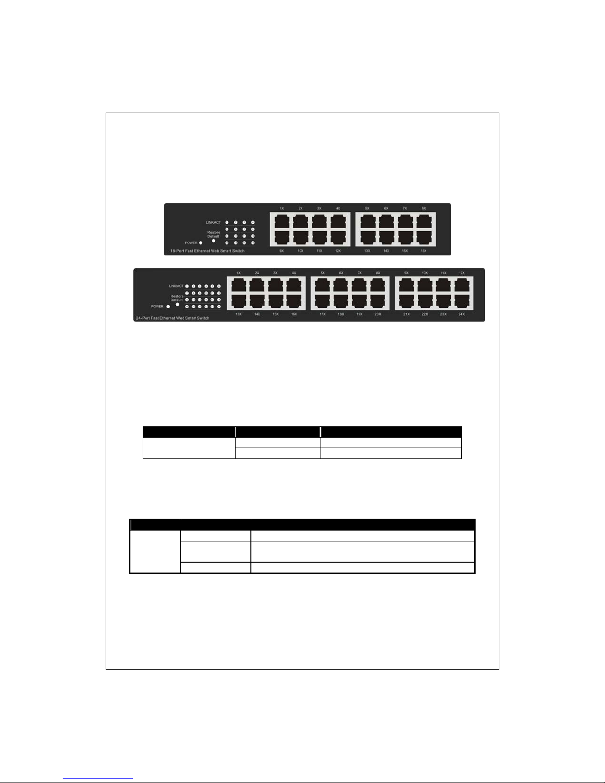
D316S / D324S Front Panel
The front panel consists of LED indicators. Please refer to the following
paragraph for information.
LEDs Definition
LED for the device:
The switch provides a power LED for the device.
LED Status Operation
Power
LED for each port:
LED Status Operation
Green The port is conne cted.
LINK/ACT
Blinking Green
Off No valid link on this port.
Steady Green The switch is powered on
Off The switch is powered off
A valid link is established, and there is data
transmitting/receiving.
Port Operation
The auto-negotiation feature allows those p orts running at one of the
6
Page 7

following operation modes:
Media Speed Duplex Mode
10/100Mbps(copper) 10Mbps Full Duplex
Half Duplex
100Mbps
Restore Default Button
You can use this button to reset the switch or restore factory defaul t settings.
To reset the switch, press the button once.
To restore fac tory default settings, press and hold the b utton for three
seconds.
Full Duplex
Half Duplex
The Rear Panel
Power Receptacle
To be compatible with the electric service standards around the world, the
switch is designed to afford the power supply in the range from 100 to
240VAC, 50/60Hz. Please make sure that y our outlet standard to be within
this range.
T o power on the switch, please plug the female end of the power cord firmly
into the receptacle of the switch and the other end into an electric service
outlet. After the power cord installation, please check if the power LED is lit
for a normal power status.
7
Page 8

Installation
This switch can be placed on your desktop directly, or mounted in a rack.
Please refer to the instructions for installation.
Before installing the switch, we recommend:
1. The switch is placed with appropriate ventilation environment. A
minimum 25mm space around the unit is recommended.
2. The switch and the relevant components are away from sources of
electrical noise such as radios, transmitters and broadband amplifiers
3. The switch is away from environments beyond recommend moisture
Desktop Installation
1. Install the switch on a level surface that can support the weight of the
unit and the relevant components.
2. Plug the switch with the female end of the pro vided power cord and plug
the male end to the power outlet.
Rack-mount Installation
The switch may be standalone, or mounted in a rack. Rack mounting
facilitate to an orderly installation when you are going to install series of
networking devices.
Procedures to Rack-mount the Switch:
1. Disconnect all the cables from the switch before continuing.
2. Place the unit the right way up on a hard, flat surface with the front
facing you.
3. Locate a mounting bracket over the mountin g holes on one side of the
unit.
4. Insert the screws and fully tighten with a suitable screwdriver.
5. Repeat the two previous steps for the other side of the unit.
6. Insert the unit into the rack and secure with suit able screws.
7. Reconnect all the cables.
8
Page 9

Installing Network Cables
1. Crossover or straight-through cable: All the ports on the switch
support Auto-MDI/MDI-X functionality. Both straight-through or
crossover cables can be used as the media to connect the switc h with
PCs as well as other devices like switches, hubs or router.
2. Category 3,4,or 5 cable: To make a valid connection and obtain the
optimal perfor mance. An approp riate cable that corresponds to different
transmitting/receiving speed is required. To choose a suitable cable,
please refer to the following table.
Media Speed Wiring
10/100Mbps copper 10Mbps Category 3,4,5 Utp/STP
100Mbps Category 5 UTP/STP
9
Page 10

Functional Description
Flow Control and Back Pressure
Flow control and Back Pressure both contributes for lower and higher speed
devices to communicate to each oth er hence ensures the correctness of
data transmitting. The 802.3x fl ow co nt rol an d Ba ck Pres sur e me ch an is ms
work respectively for full and half duplex modes. Flow control can be
enabled or disabled on a per-port basis.
Mirror
The Mirror function provid es network admi nistrator to monitor the traf fic. By
forwarding a copy of the packets that transferred by the monitored port, the
sniffer port received all the packets and hence is able to monitor the traffi c
of the specified port.
VLAN
With VLAN supported, the network can be segmented in groups to reduce
the collisions from widely broadcasting. The device supports port-based
VLAN.Port-based VLAN classifies incomi ng packets to VLANs according to
their ingres s p ort.
Trunk (Aggregation)
The Trunk functionality integrates several ports to enlarge the bandwidth
that helps to boost the backbone connectivity. The switch allows the
Maximum 2 group and 4 members for each group.
Quality of Service (QoS)
The QoS service classifies packets into different precedence. The packets
are transmitted and received by t heir classi fied priorit ies. This mec hanism
helps high bandwidth demanded applications such as VoIP to get an
unobstructed connection.
10
Page 11
Management guide
Access the Switch
This section instructs you how to enter and proceed the advanced
management capability, which can be accessed by Telnet session /
Internet Browser over the network (in-band).
To access the Web-based management interface, you should configure the
management station with an IP address and subnet mask that compatible to
your switch.
The factory default value of the switch:
IP: 192.168.1.1
Subnet Mask: 255.255.255.0
Default Gateway: 192.168.1.254
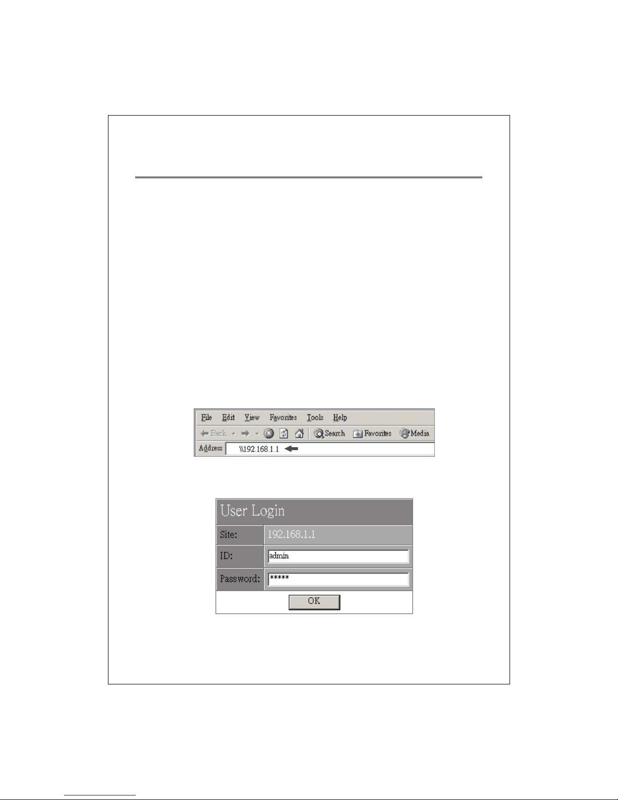
1. Running your Web Browser and ent er the IP address “192.168.1.1” in the
Address field.
2. Key in the us er name and pa sswo rd to pass the authentication. The fac tory
default value of User Name and Password is “admin”.
11
Page 12
Homepage
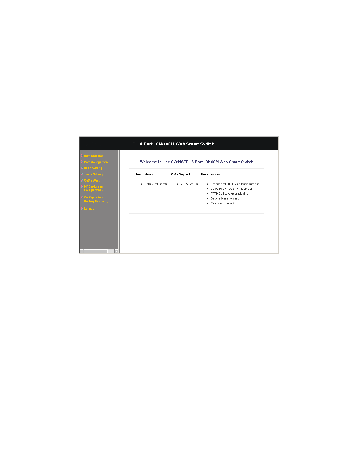
After authentication procedure, the welcome page shows up as the
Homepage. You may click the hyperlinks on the left side of each page to get
access to each management functions.
12
Page 13
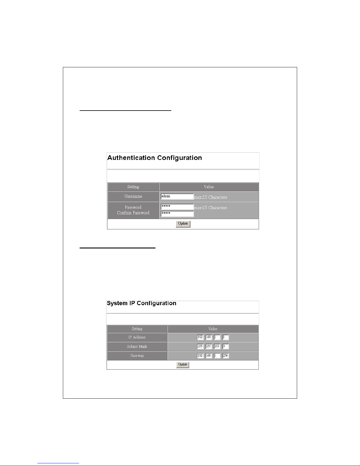
Administrator
Authentication Configuration
Specify the username/password for accessing this Graphic User Interface.
Please fill in your desired username and password in the designated boxes
respectively then click the update button to perform changes.
Note: The default username/ password is admin/ admin.
System IP configurat ion
This page allows users to change the IP addresses of this device. Fill in the
parameters and click Update to change the IP addresses.
Note: The factory default value of the switch:
IP: 192.168.1.1
Subnet Mask: 255.255.255.0
Default Gateway: 192.168.1.254
13
Page 14
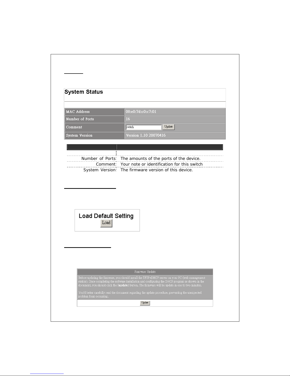
System
The system information of this device
Items Functions
MAC Address The MAC address of this device..
Number of Ports The amounts of the ports of th e device.
Comment Your note or identification for this switch
System Version The firmware version of this device.
Load Default Setting
This page allows users to load the default settings of the device. Please note
that your configurations to this device will be completely removed.
Firmware Upgrade
Use this page to update a new firmware for this device. Please note that you
should install TFTP and DHCP server on your PC first before performing
firmware upgrading.
14
Page 15
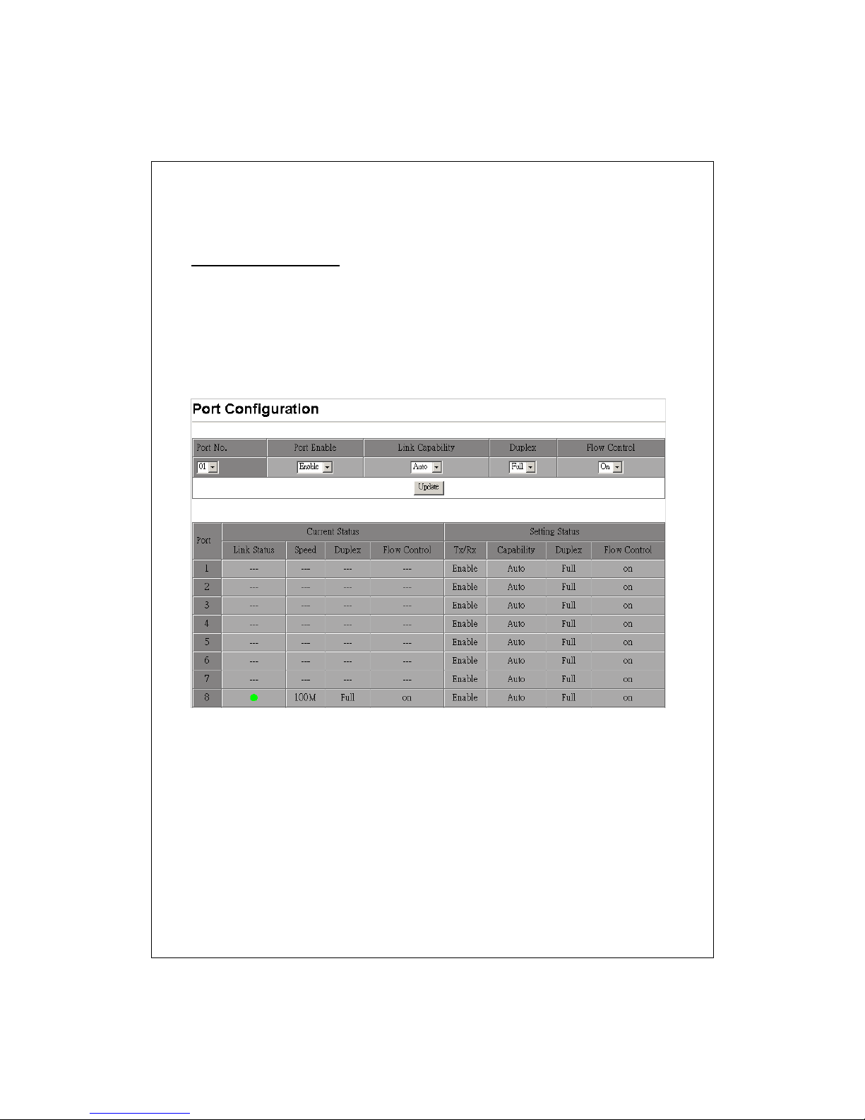
Port Management
Port Configuration
This page shows the status on each port, and provides port properties
configuration. To configure each port:
1. Select the port that you are going to configure on the Port No. drop list.
2. Select each item in drop list.
3. Click the Update button to perform your changes.
15
Page 16
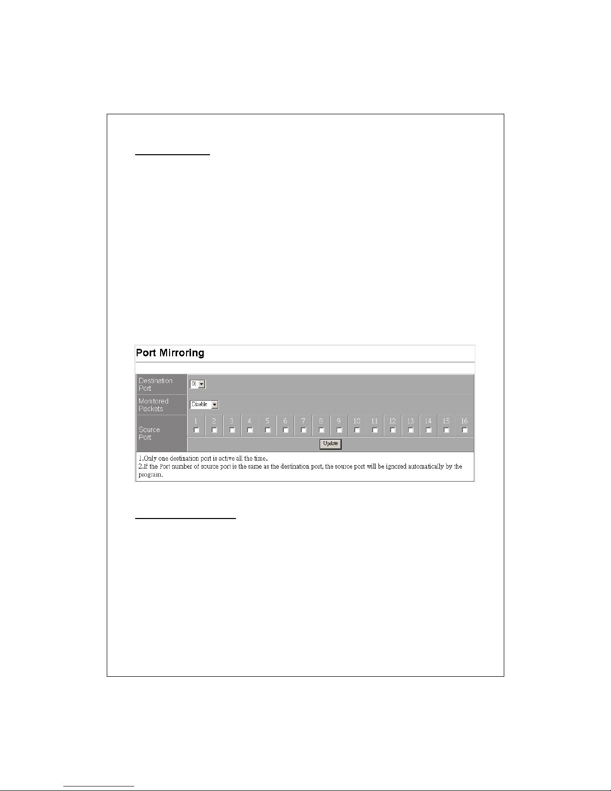
Port Mirroring
The Mirror function copies all the packets that are transmitted by the
source port to the destination port. It allows administrato rs to analyze and
monitor the traffic of the monitored ports.
Mirror Configuration:
1. Select those ports that are going to be monitored by marking the
checkboxes in “Source Port” column.
2. Click the drop list in “Monitored Packets” column. Select the packet
types that are going to be monitored (tr ansferred or received packets or
both).
3. Select a port as the administration port for monitoring those source
ports in the “Destination Port’ drop list.
4. Click “Update” to activate.
Bandwidth Control
This “Bandwidth Control” page allows users to configure the bandwidth
for each port.
To perform speed configuration for each port:
1. Select the port that you are going to configure on the “Port No.” drop list.
2. S elect the allo wed transmitting and rec eiving speed for this port .
3. Click the Update button to perform your changes.
4. You may also click the “LoadDefault” button to restore the factory
default bandwidth setting.
16
Page 17
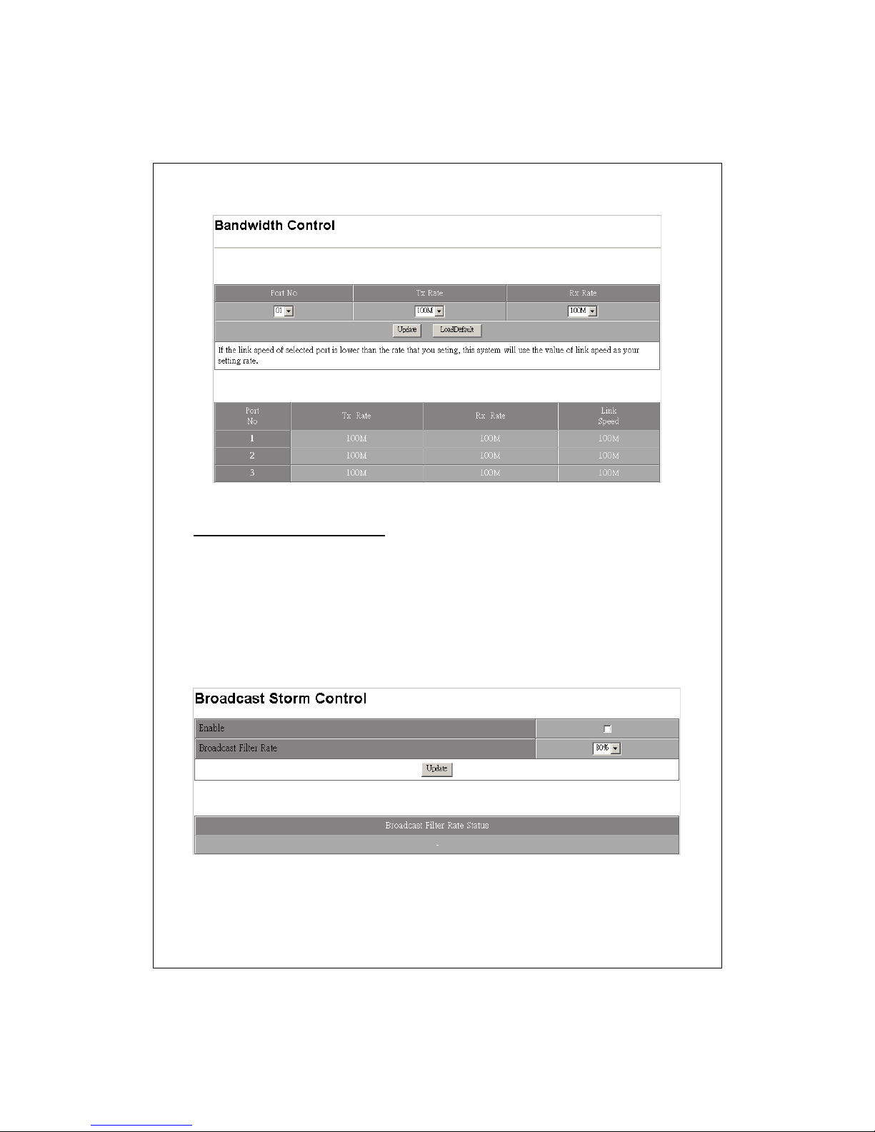
Broadcast Storm Control
This function prevents the bandwidth from overloaded by broadcast pack ets.
To activated this function:
1. Mark the “Enable” checkbox.
2. Select the rate of the broadcast packets that are going to be
dropped by the Broadcast Filter.
3. Click the “Update” button to activate the broadcast filter
function.
17
Page 18
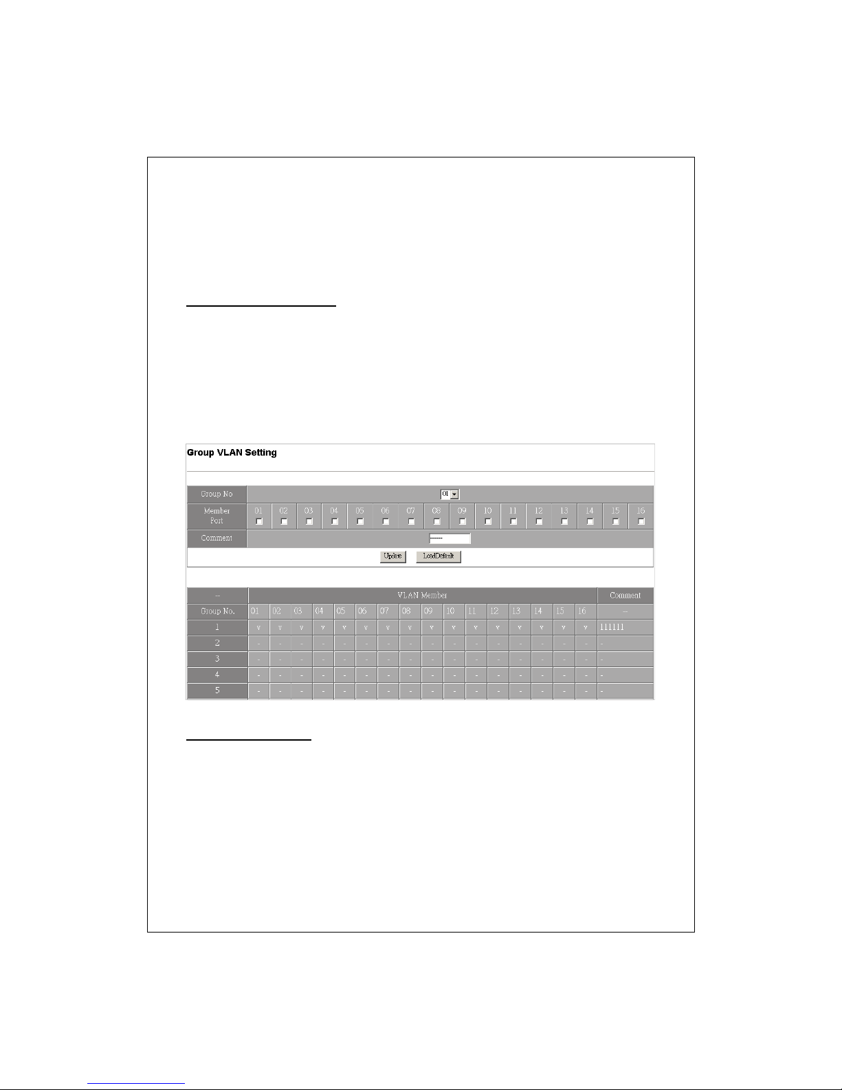
VLAN Setting
VLAN divides the network members into groups to reduce packets collisions
and improve the network efficiency. Please follow the instructions to
configure.
Group VLAN Setting
1. Select a group in the “Group NO” drop list.
2. Select the members of the group by marking the “Member Port”
checkbox.
3. Fill in your note for this group in the “Comment” blank than click the
Update button to create a VLAN group.
4. You could also restore the default settings of VLAN by clicking the
“LoadDefault” button.
Multi to 1 Setting
This function provides users to separate the ports on this device in two
groups quickly. Those selected ports will be banned from connecting with
the destination port.
To start this function:
1. Choose a destination port.
2. Select those ports that are NOT allowed to connect with the destination
port.
18
Page 19
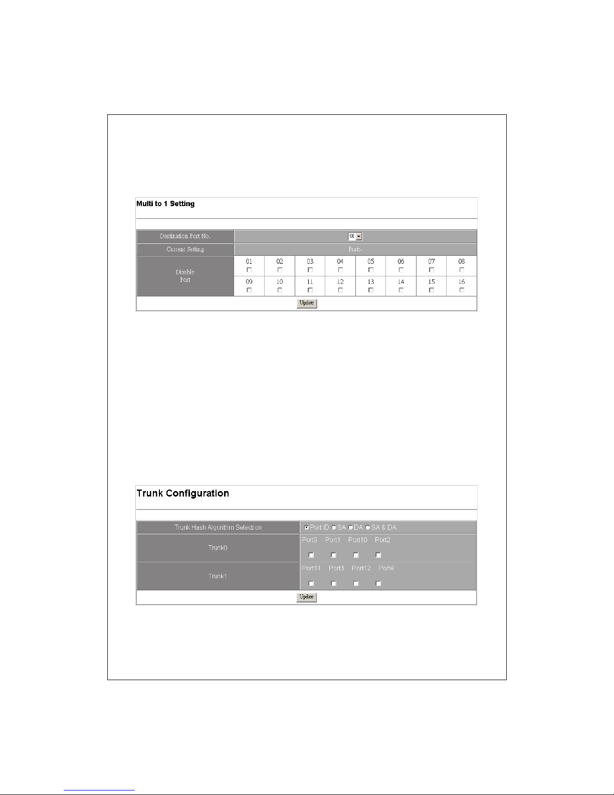
3. Click the Update button to activate.
Note: While the group setting in “Multi to 1” conflicts with “Group VLAN
setting” the system ignore your configuration on “Multi to 1” function.
Trunk Setting
To set up the Port trunk groups:
1. Select a trunk mode in the algorithm selection column. There are three
aggregation modes for you to setup, SA, DA, and SA+D A. SA mode
selects the path of packets according to source MAC Address while
DMAC mode selects path according to destination MAC Address. SA+DA
mode calculates the result of SA and DA mode to decide the path of
packets.
2. Select the members in Trunk 0 or Trunk 1 group .
3. Click the Update button to activate your configuration.
19
Page 20
T
T
g
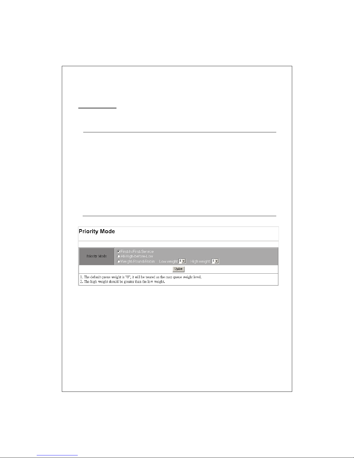
QoS Setting
Priority Mode
This page allows users to designate a QoS mode of this switch. You can
select from three modes:
First-In-First-Service
All-High-Before-Low The QoS function is enabled and the sw itch will deliver
Weight-Round-Robin
he QoS function is disabled. The switch deliver the
packets according to the time that the packets came
in.
low-priority packets only after high-priority packets
are completely delivered.
he QoS function is enabled and the switch deliver
packets according the ratio of high/low packets that
you configured. To set the ratio, click on the Low/High
weight drop list.
Ex, while you configure the Low wei
High weight with 8, the switch will deliver 8
high-priority packets before sending the 2 low-priority
packets.
ht with 2 and
20
Page 21
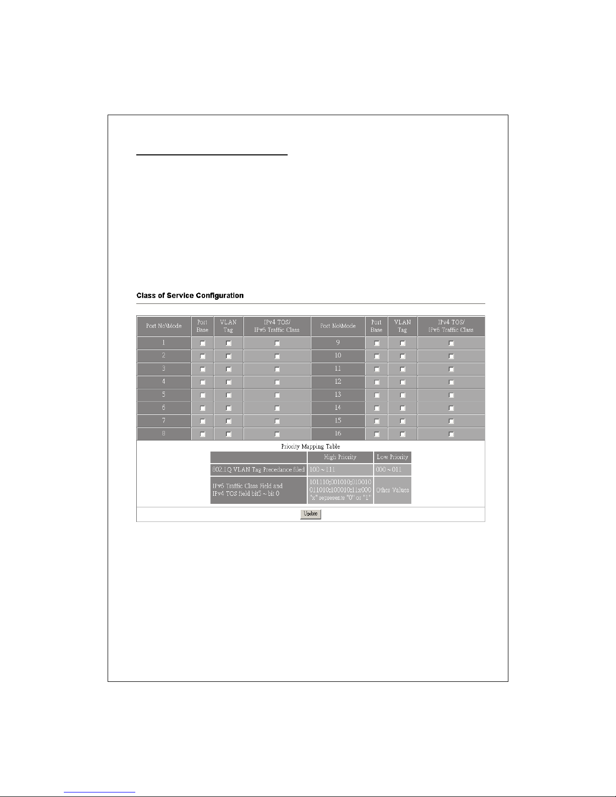
Class of Service Configuration
Use this page to configure the priority level for each port. To set the priority,
please mark the ports that you would like to set as high priority on the “Port
Base”, “VLAN Tag” or Ipv4 TOS/Ipv6 Traffic Class” checkbox.
Note:
1. “Port Base”, “VLAN Tag” and “Ipv4 TOS/Ipv6 Traffic Class” are
mechanisms to identify prioriti es.
2. While there are conflictions on the three modes, the system adapts the Port
Base mode first, then the VLAN tag mode and last with Ipv4 TOS/Ipv6 Traffic
Class mode.
MAC Address Configuration
This page allows users to configure access authority by MAC address. Only the
designated MAC addresses ar e al lowed to access those configur ed ports.
To perform this function:
1. Select Enable in the Port Binding drop list
2. Select a port that you want to configure.
3. Fill in the MAC addresses that are allowed to access this port.
4. Click the Update button to activate.
21
Page 22
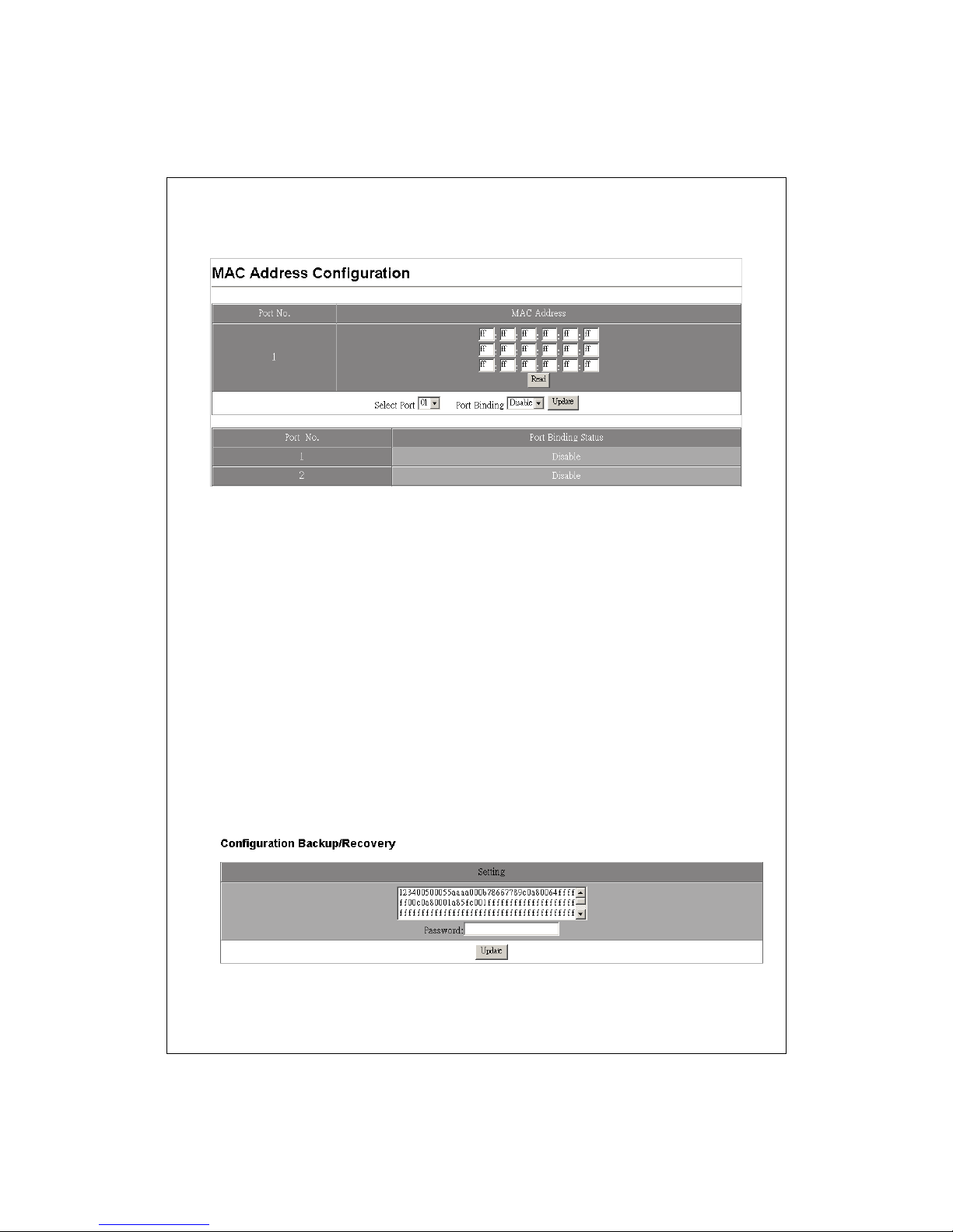
5. To change the MAC addresses, fill in the new addresses and c li ck the Read
Button.
Configuration Backup/Recovery
This function provides a quick applying while a configuration is going to be applied
on several of this product. Ple ase follow the instruction below to Sav e and load a
configuration.
Save your configuration to this product
1. Select the string in the Setting window
2. Right–click the string you selected and select copy.
3. Paste the string in a documentary file. Ex, notepad (*.txt) or Word (*.doc)
Load the configuration to this product
1. Open the file you save this string and select them all.
2. Right-click on the string you selected and s ele ct copy.
3. Enter this configuration page. Delete all th e stri ng in the Setting column.
4. Paste the string tha t you copied, fill in the pa ssword for acce ssing this dev ice
and click the Update button to load your configu ration.
22
Page 23
g
g
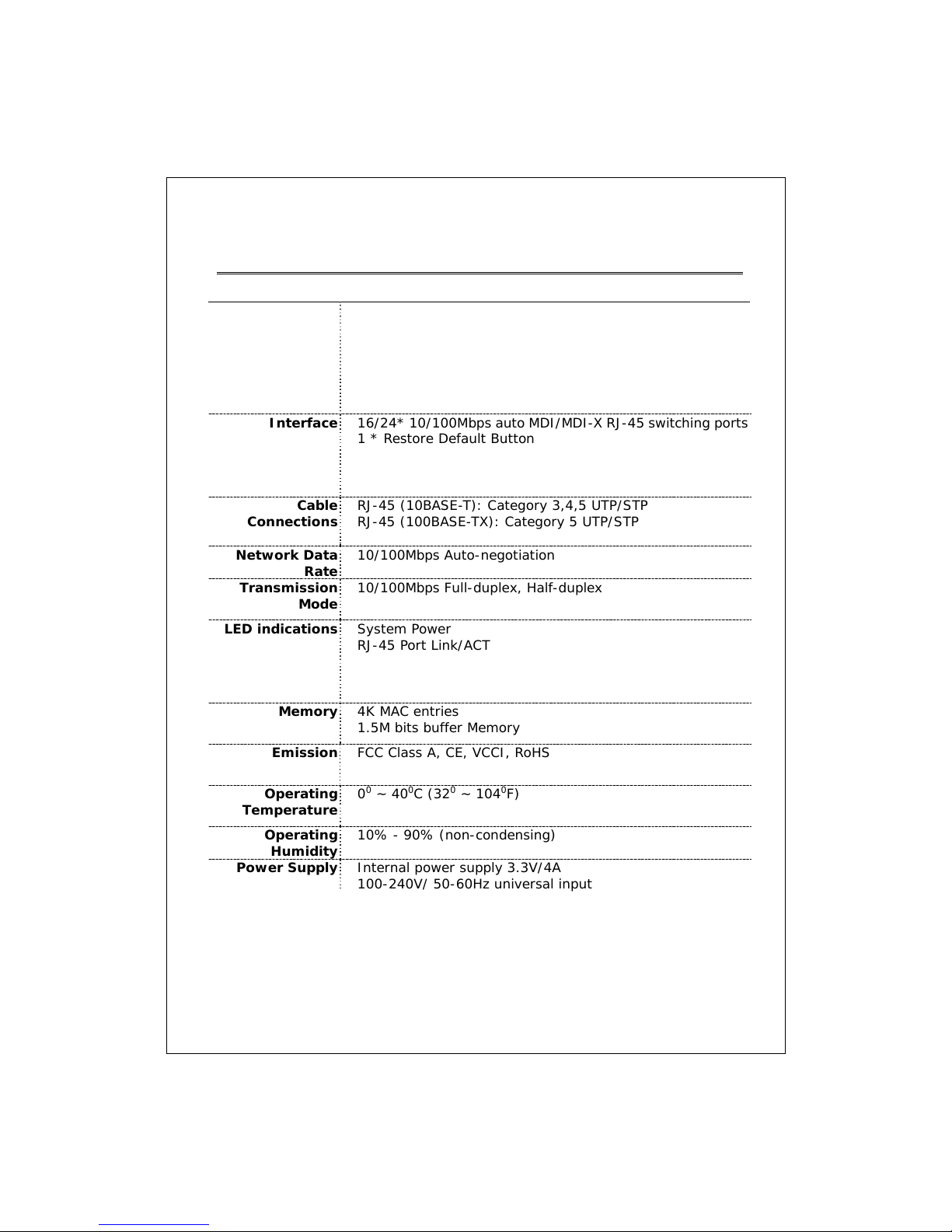
Product Specifications
Standard IEEE802.3 10BASE-T
IEEE802.3u 100BASE-TX
IEEE802.3x full-duplex operation and flow control
IEEE802.3ab/z 1000BASE-T
IEEE802.1Q VLAN interoperability
IEEE802.1p Priority Operation
Interface 16/24* 10/100Mbps auto MDI/MDI- X RJ-45 switching por ts
1 * Restore Default Button
Cable
Connections
Network Data
Rate
Transmission
Mode
LED indications System Power
Memory 4K MAC entries
Emission FCC Class A, CE, VCCI, RoHS
Operatin
Temperature
Operatin
Humidity
Power Supply Internal power supply 3.3V/4A
RJ-45 (10BASE-T): Category 3,4,5 UTP/STP
RJ-45 (100BASE-TX): Category 5 UTP/STP
10/100Mbps Auto-negotiation
10/100Mbps Full-duplex, Half-duplex
RJ-45 Port Link/ACT
1.5M bits buffer Memory
00 ~ 400C (320 ~ 1040F)
10% - 90% (non-condensing)
100-240V/ 50-60Hz universal input
© Datasheen Corporation. 2009. Taiwan
23
 Loading...