

DATASENSOR DS1 Instruction Manual
r
CTi Automation - Phone: 800.894.0412 - Fax: 208.368.0415 - Web: www.ctiautomation.net - Email: info@ctiautomation.net
DS1 SERIES
OUT LED on receiver (RX)
The yellow LED ON indicates the presence of the object into controlled area.
POWER ON LED on receiver (RX)
The green LED ON indicates the optimal device functioning.
The fast blinking of the green LED indicates a critical device alignment.
Please refer to “DIAGNOSTICS” paragraph for other indications.
POWER ON LED on emitter (TX)
The green LED ON indicates the correct device functioning.
Please refer to “DIAGNOSTICS” paragraph for other indications.
General information on device positioning
• Align the two receiver (RX) and emitter (TX) units, verifying that their distance is inside
the device operating distance, in a parallel manner, placing the sensitive sides one in
front of the other, with the connectors oriented on the same side. The critical alignment
of the unit will be signalled by the fast blinking of the green receiver LED.
• Mount the receiver and emitter units on rigid supports which are not subject to strong
vibrations, using specific fixing brackets and /or the holes present on the device lids.
Precautions to respect when choosing and installing the device
• Choose the device according to the minimum object to detect and the maximum
controlled area requested (= operating distance x controlled height);
• In agroindustrial applications, the compatibility of light grid housing material and any
chemical agents used in the production process has to be verified with the assistance
of the DATASENSOR technical sales support department;
• The AREAscan
the safety control of the machines where installed.
Moreover the following points have to be considered:
- avoid installation near very intense and / or blinking light sources, in particular near to
the receiver unit;
- the presence of strong electromagnetic disturbances can condition the correct
functioning of the device; this condition has to be carefully evaluated and checked with
the DATASENSOR technical sales support department;
- the presence of smoke, fog and suspended dust in the working environment can
reduce the operating distance of the device;
- strong and frequent temperature variations, with very low peak temperatures, can
generate a thin condensation layer on the optics surfaces, compromising the correct
functioning of the device;
- reflecting surfaces near the luminous beam of the AREAscan
or lateral) can cause passive reflections able to compromise object detection inside the
controlled area.
if different devices have to be installed in adjacent areas, the emitter of one unit must not
interfere with the receiver of the other unit.
General information relative to object detection and measurement
For a correct object detection and / or measurement, the object has to pass completely
through the controlled area; testing the correct detection before beginning the process is
suggested.
INSTRUCTION MANUAL
CONTROLS
INSTALLATION MODES
TM
light grids are NOT safety devices, and so MUST NOT be used in
TM
device (above, under
CONNECTIONS
EMITTER
(TX):
M12
4-pole connector
NOT USED
0 V
+24 Vdc
1
2
SYNC ( RX)
4
3
ANALOGUE
OUTPUT
RECEIVER
(RX):
M12
5-pole connector
Shielded cables are not foreseen in the standard
2
3
0 V
1 – brown: +24 Vdc 1 – brown: +24 Vdc
2 – white: Analogue output 2 – white: Not used
3 – blue: 0 V 3 – blue: 0 V
4 –black: Switching output 4 – black: SYNC
5 – grey:
5
SYNC
1
4
+24 Vdc
SYNC ( TX)
SWITCHING
OUTPUT
connection.
Ground connection of the two units is not necessary. If
desired, this connection can be accomplished replacing
the screw provided in the packaging with the one
indicated in the drawing, which blocks the lid of the
connector side of each unit.
It is necessary to respect the connection shown in the
drawing if ground connection of the entire system is
requested.
FUNCTIONING AND PERFORMANCES
The beam interruption due to the passage of an object inside the controlled area caused
the closing of the switching output and the variation of the device analogue output signal.
Small objects can be detected (reaching dimensions of only 5 mm) and determine linear
measurements with a ±3 mm error in best cases.
In particular:
The switching output is always activated when at least one beam is obscured. The status
variation is signalled by the yellow receiver LED that turns on.
The analogue output value (0-10 V) is proportional to the number of obscured beams (0V
means that no beam is interrupted, 10V all beams interrupted)
The device does not require calibration; periodical checks of the resolution and / or
measurement are however suggested.
The blinking of the green receiver LED (stability function) signals the critical alignment of
the units and / or the functioning outside or near the maximum operating distance. In
optimal conditions the LED remains on continuously.
The two units are synchronised via cable (SYNC wire); precarious connections or
induced disturbances on the synchronism line can cause device malfunctioning or a
temporary blocking.
The diagrams, given below, show the typical minimum resolution trend of each model, SR
(standard resolution) and HR (high resolution), in according to the operating distance (D).
TECHNICAL DATA
Power supply:
Consumption on emitting unit
(TX):
Consumption on receivingr unit
(RX):
24 Vdc ± 15%
150 mA max.
50 mA max without load
Switching output:: 1 PNP output
Switching output current: 100 mA; short-circuit protection
Output saturation voltage:
≤ 1.5 V at T=25 °C
Analogue output: 0-10V proportional to obscured beams
Analogue output current:
10 mA max. (1KΩ proportional to obscured beams)
Minimum resolution: 5 mm (refer to “Specifications” table)
Measurement precision: ± 3.5 mm (refer to “Specifications” table)
Response time: 1 ms (refer to “Specifications” table)
Indicators:
RX: OUT LED (yellow) / POWER ON LED (green)
TX: POWER ON LED (green)
Operating temperature: 0…+ 55 °C
Storage temperature: -25…+ 70 °C
Operating distance (typical
values):
0.15 - 2.1 m
Emission type: Infrared (880 nm)
Vibrations: 0.5 mm amplitude, 10 … 55 Hz frequency, for every
axis (EN60068-2-6)
Shock resistance: 11 ms (30 G) 6 shock for every axis (EN60068-2-27)
Housing material: Black electro-painted aluminium
Lens material: PMMA
Mechanical protection: IP65 (EN 60529)
Connections: M12 4-pole connector for TX
M12 5-pole connector for RX
Weight: 300 g. (DS1-xx-010-xx)
340 g. (DS1-xx-015-xx)
510 g. (DS1-xx-030-xx)
DIAGNOSTICS
RECEIVING UNIT:
Segnal Status Cause Action
OUT LED
POWER ON
LED
EMITTING UNIT:
Segnal Status Cause Action
POWER ON
LED
ON
OFF
ON
Fast blinking
Slow blinking
OFF
ON
Blinking
OFF
Switching output.
Presence of the object in
the controlled area.
Switching output.
Controlled area free of
objects.
Optimal functioning
Critical alignment of the
unit or/and functioning
closed to maximum
operating distance.
Wrong connections
and/or malfunctioning.
Device is not powered. - Verify the connections.
Normal functioning of
emission unit.
Unit malfunctioning - Switch OFF and switch ON the
Absence of powering
and/or synchronism with
receiver
- Verify the output connections
and any short- circuits
- Switch OFF and switch ON the
device.
- If condition persists, contact
Datasensor.
- If condition persists, contact
Datasensor.
device.
- If condition persists, contact
Datasensor.
- Verify the connections and right
value of power supply.
- If condition persists, contact
Datasensor.
SPECIFICATIONS
Model
DS1-LD-SR-010-xx
DS1-LD-HR-010-xx
DS1-LD-SR-015-xx
DS1-LD-HR-015-xx
DS1-LD-SR-030-xx
Controlled
height
(mm)
100 16 7 0.63
100 32 5 0.31
150 24 7 0.42
150 48 5 0.21
300 48 7 0.21
N°.
beams
Minimum
resolution
(mm)
Output
analogue
sensitivity
(V)
Measurement
precision
(mm)
± 7
± 3.5
± 7
± 3.5
± 7
Response
time
(ms)
1 0.15…2.1
2 0.15…2.1
1.5 0.15…2.1
2.75 0.15…2.1
2.75 0.15…2.1
Operatine
distance
(m)
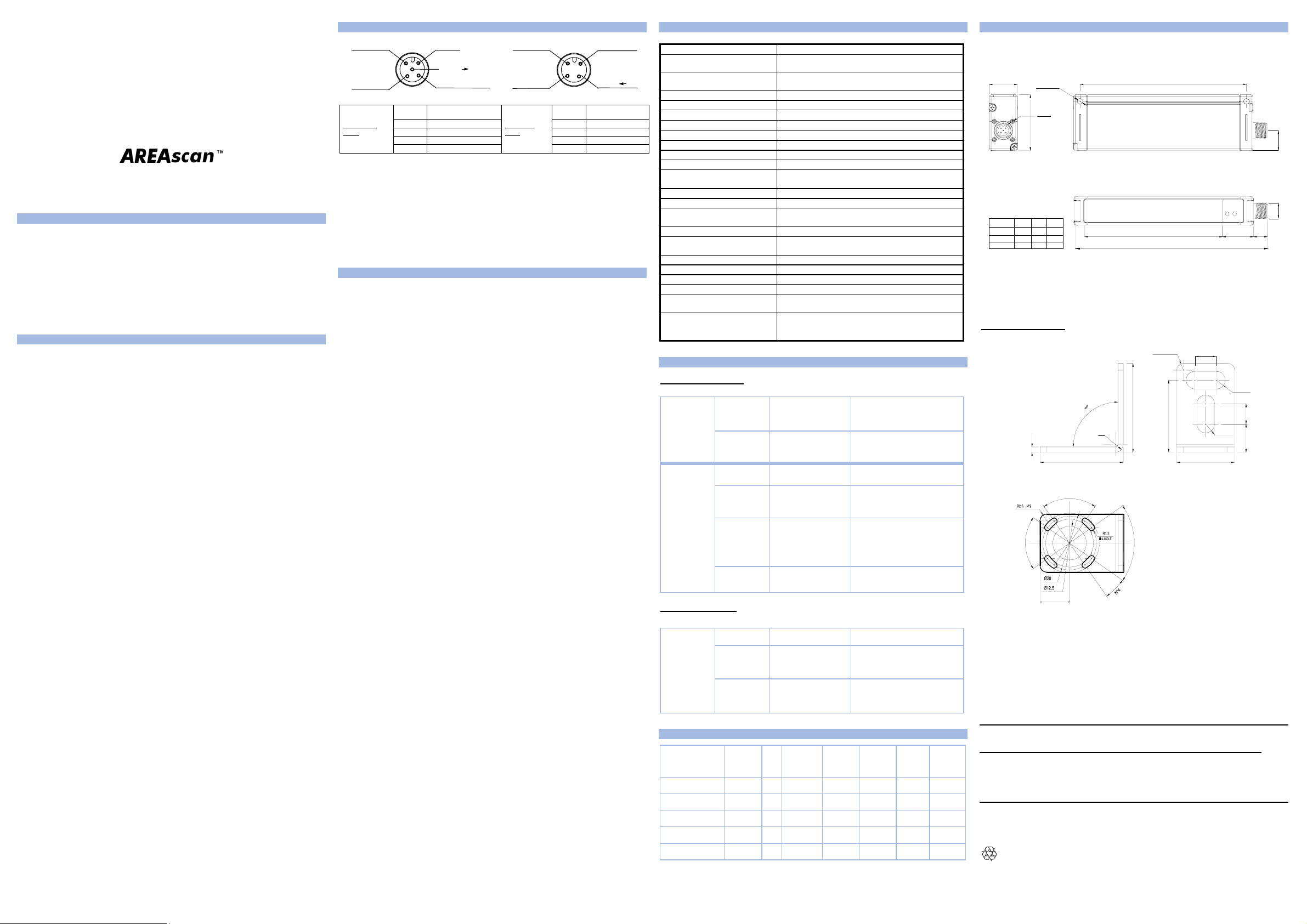
DIMENSIONS
22
DS1-010
DS1-015
DS1-030
L1
150.1
200.1
350.1
Ø4.5 N°2
M2 N°4
43.2
L2 L3
107
157
307
129.1
179.1
329.1
L3
15.5
mm
M12
10.8
24L2
L1
FIXING BRACKET
90
31
70°
R3
°
0
2
826003140 Rev.A
2
70°
11
The fixing bracket is supplied with the product.
DECLARATION OF CONFORMITY
We DATASENSOR S.p.A. declare under our sole responsibility that these products are conform to the
2004/108/CE, 2006/95/CE Directives and successive amendments.
WARRANTY
DATASENSOR S.p.A. warrants its products to be free from defects.
DATASENSOR S.p.A. will repair or replace, free of charge, any product found to be defective during the
warranty period of 36 months from the manufacturing date.
This warranty does not cover damage or liability deriving from the improper application of
DATASENSOR products.
DATASENSOR S.p.A. Via Lavino 265
40050 Monte S. Pietro - Bologna - Italy
Tel: +39 051 6765611 Fax: +39 051 6759324
http://www.datasensor.com e-mail: info@datasensor.com
DATASENSOR S.p.A. cares for the environment: 100% recycled paper.
DATASENSOR S.p.A. reserves the right to make modifications and improvements without prio
notification.
R2.5 N°2
33
33
26.8
70°
8
R3.3
R3.3
10.5 7.5
21.6
 Loading...