

Page 1

OPERATING
INSTRUCTIONS
V:\.:-.-.
ACCUTORR
ACCUTORR
3/ACCUTORR
4/ACCUTORR
Datascopef
3SAT/
4SAT
Page 2
Table
of
Contents
FOREWORD
SAFETY
PRODUCT
CONSIDERATIONS
LIMITATIONS
UNPACKING
SERVICING
10
GENERAL
1.1
General
1.2
Specifications 1-3
INFORMATION
DESCRIPTION
AND
SPECIFICATIONS
Description 1-1
Sa02
NIBP
LCD Display 1-4
Trend
Printer
Mechanical
Power
Environmental
Requirements
Battery 1-5
Agency
Compliancies
Mi
Hi
iv
v
vi
M
1-3
1-3
1-4
1-4
1-4
1-5
1-5
1-5
2.0
CONTROLS
2.1
2.2
3TQ
Front
Rear
Panels
Panel
OPERATION
Abbrievated
Detailed
Operating
3.1 Setting-Up
3.2
Turning
3.3
Initial
3.3.1 View
3.4
Operation
3.4.1
3.4.2
3.4.3
Manual
Automatic
NIBP
Power
Control
Angle
Pressure
Operating
On
Settings
(Contrast)
Initiation
Initiation
AND
INDICATORS
Instructions
Instructions
of
NIBP
of
Limit
Fail
Measurements
NIBP
Measurements
Safe
, . , .
2-1
2-2
2-7
3=1
3-1
3-2
3-2
.3-2
3-3
3-3
3-4
3-4
3-6
3-7
Revised
12/21/89
Page 3

3.4.4
3X5
3.4.6
3.4.7
3.4.8
3.4.9
3.4.10
3.4.11
3.4.12
3.4.13
Cuff
Inflation
START
Sequence
Sensors
LCD
Messages
Alarms
Trend
Printer
User
Configuration 3-21
Time
and
HOLDFunctions 3-7
for Establishing
and
Indicators
Sa02
3-7
3-8
3-8
3-13
3-15
3-18
3-20
Interfacing 3-24
4.0
4.1
4.2
4.3
4.4
4.5
4.6
4.7
4.8
5.0
5.1
5.2
6.0
6.1
6.2
6.3
6.4
6.5
6.6
USER
Introduction
Care
Care
Sterilization
Battery
Paper
Sterilization of
MAINTENANCE
and
Cleaning of Monitor 4-1
and
CleaningofSensors
of
Sensors
Replacement
Replacement
Disposable
and
Maintenance 4-2
Cuffs 4-4
HorizontaltoVertical Configuration 4-4
ACCESSORIES
Standard
Optional
Accessories
Accessories
APPENDIX
Warranty
Indirect
Precautions
Cuff
User
References
Blood
with Using Automatically Cycled Blood
Bleed
Verification
Rate
Pressure
Selections
of
ACCUTORR
Measurements
Measurements
and
Associated
Pressure
Errors
Cuffs
...
4J.
4-1
4-1
4-2
4-3
5=1
5-1
5-1
6=1
6-1
6-2
6-2
6-3
6-3
6-5
Revised
08/01/90
Page 4
FOREWORD
This manual is intended to provide informationfor the proper operation of
the
Datascope ACCUTORR 3/4 Monitor.
General knowledge of monitoring and an understanding of the features
of
the
Datascope
DO
NOT
OPERATE
Information for servicing this instrument is contained in
ACCUTORR
ACCUTORR
THIS
3/4 Service
3/4
MONITOR
Manual,
are
prerequisites for its
BEFORE
Part
No.
0070-00-0221. Foradditional information"
READING
proper
THESE
the
Datascope
use.
INSTRUCTIONS.
and
functions
or assistance, please contact an authorized Datascope representative inyour area.
Federal Law restricts this device to
titioner licensed by
NOTE: Inordertoensure
state
law to
the
to prevent the voiding of the warranty, it is recommended that only parts
sories
provided by
Datascope
sale
use
by or on the
or order
the
order
use
of this device.
of a physicianorother
proper performance of your monitoring equipment
and
acces
be
used
with your monitor.
SAFETY CONSIDERATIONS
Please
this
read
instrument:
and
adheretothe
following safety considerations regarding
the
use
of
,
prac
and
•
Possible
presence
Association
no
less
• Internal Electrical
Explosion Hazard - This instrument is not explosion-proof. In
of flammable
Code,
than
five
feet
gases
NFPA 56A,
above
Shock
the
Hazard
and
in accordance with
the
Datascope
floor.
- This unit
the
ACCUTORR
does
not
contain
National Fire Protection
3/4
must
any
the
be
operated
user-service
able parts. Do not remove instrument covers. Refer servicing to qualified person
nel.
•
Observe
•
RS232
on
this unit
• Always
• Never
• For
type
Do
ment.
all
Connector
place
place
continued
and
rating.
not
leave
CAUTION
-
may
cause
the
monitorona rigid, flat surface.
fluids
on
protection
See
the
patient
and
WARNING
Connection
chassis
top
of this monitor.
against
the
ACCUTORR
unattended
labels
of
non-isolated
leakagetoexceed
a fire hazard,
3/4
on
the
monitor.
devices
replace
to
the
specification
all
the
fuses
RS232
with
Connector
standards.
the
Service Manual, P/N 0070-00-0221.
for long periods of time while using this instru
specified
Revised 03/11/91
III
Page 5
• Cuffs mustbeused
•
Use
only
Datascope
with Datascope hoses because of safety luer
accessories
with this product.
fitting.
• This instrument is calibrated to read percentage
oxygen
saturationoffunctional
hemoglobin (Sa02). Significant levels of dysfunctional hemoglobin,
carboxyhemoglobin or methemoglobin, affect the accuracy of the
ment.
• This instrument
on
See
the
appendix for a bibliography of related articles.
may
have
trouble obtaining heart rate,
patients undergoing intra-aortic balloon
pump
Sa02
treatment.
Sa02
and
NIBP readings
• Administrationofcertain vasoconstrictive drugs, i.e., norepinephrine,
peripheral perfusiontoa level that prevents
ACCUTORR4SAT
• Arterial
compression,
perfusionofthe
ACCUTORR
• Intravascular
Sa02
•
Wrapping
measurement.
the
• Overwrapping
3/4
dyes,
cuffs
from taking
tricuspid regurgitation, or other conditions
plethysmograph
from
taking
depending
too
of
SD FLEXISENSOR
Sa02
tightly
Sa02
waveform to a level that
on
concentration,
may
cause
and
and
bandage
the
Datascope
pulse rate
pulse
rate
measurements.
may
a hazardtothe
may
cause
ACCUTORR3SAT
measurements.
may
prevents
affect
the
accuracyofthe
patient.
a hazardtothe
the
such
measure
may
reduce
as
reduce
and
patient.
This
unit
must
•
•
When
the
equipment
PRODUCT
onlybeoperated
integrityofthe
should
LIMITATIONS
• Monitor accuracy
•
• If
•
3.4.1
The
The
the
for
detailed
sions
the
ment
monitor
or
pressure
may
heart rate
will
tremors.
cuffisnot
be
subjecttoerror,
data
measurementofperipheral pulses (peripheral
urement
from
that
cycle).
the
rateofan
may
not always result in a peripheral pulse.
protective earth
be
operated
depends
information.
not
operate
placedatthe
displayedonthe
The
rate
measuredbythe
ECG monitor.
with Datascope
conductor
from its internal battery.
on
the
application of
effectively on patients
patient's heart level,
duetothe
hydrostatic effect.
Datascope ACCUTORR
Datascope ACCUTORR 3/4
Thisisbecause
approved
arrangement
the
proper cuff size.
who
pulses
the
software.
are experiencing convul
taken
ECG is
is in
doubt,
See
the
NIBP
measure
3/4iscomputed
only during a
may
an
electrical signal
the
Section
from
meas
differ
iv
Revised
07/02/90
Page 6
• Administrationofcertain vasoconstrictive drugs i.e., norepinephrine,
peripheral
and
•
Arterial
fusion or
taking
pulse
perfusion to a
rate
measurements.
level
that prevents the
ACCUTORR
3/4
from
compression, tricuspidregurgitation, or other conditions may reduce per
the
Sa02
Sa02
and
waveform to a level that prevents the ACCUTORR 3/4 from
pulse
rate
measurements.
may
reduce
taking Sa02
• The presence of arrhythmias may increase the time required to complete a
urement and may extend this time to a pointwhere a measurement cannot be
completed.
• The Datascope ACCUTORR 3/4 is not intended for
uses
an oscillometric technique
blood
pressure
measurements.
based
on normal peripheral circulation to compute
• On occasion, increased motion, prolonged crying, or hyperactivity
measurements
UNABLE
TO
with an advisory indication of RETRY-MOTION ARTIFACT or
MEASURE.
use
during CPR. The monitor
may
UNPACKING
Remove
damage.
process
to
tact
tance
the
instrument from
Save
all packing materials, invoice, and
a claim with
the
Datascope
in resolving shipping problems.
Customer
the
the
carrier.
Service
shipping carton and examine it for
billoflading.
Check
all
materials against
Department (800) 288-2121 for
These
the
signs
packing list.
of shipping
may
be
prompt
meas
produce
required
Con
assis
Page 7

SERVICING
INFORMATION
DATASCOPE
maintains a network of service representatives and factory-trained dis
tributors. Priorto requesting service, perform a complete operational check of the in
strumenttoverify proper control settings.Ifoperational problems continue to exist
contact
determining
the
Datascope
the
nearest
Customer
field
service
Service Department (800) 288-2121 for
location.
assistance
Please include the instrument model number, the serial number, and a description of
the
problem with all
Any
questions
Domestic
Service
Datascope
30
Paramus,
Park
Manager
Corp.
Place
NJ
(201)265-8800
(800)288-2121
Service
Datascope
1133
Fullerton,
Manager
S.
Placentia
CA
Corp.
(714)738-3996
Offices:
07652
92631
requests
regarding
Ave.
for service.
the
warranty should
Service
Datascope
Manager
Corp.
be
1111 Pasquinelli Dr.,Su'ite
Westmont,
III
60559
(312)325-7737
Service
Datascope
4100
Ft.
Manager
Amon
Worth,
Corp.
Carter
TX
Blvd.,
76155
(817)354-8833
directed to:
200
Suite
106
Service
Datascope
1900
Smyrna,
Manager
Lake
GA
Corp.
Park
(404)436-9963
Dr.,
30080
Suite
in
300
International
Service
Datascope
Postbox
Hoevelaken,
03495-34514
Service
Datascope
Immeuble
65
93100
France
011-331-485
Copyright
Avenue
Montreuil
99844
Manager
B.V.
26,
3870
Holland
Manager
S.A.R.L
Rond
DU
General
(c)Datascope
of this publication
Datascope
Corp.
Offices:
CA
Point
Sous
93
may
Service
Datascope
Am
West
421-321818/19
Gallieni
Bois
Manager
Dobben
Germany
Corp.
10,
Corp., 1989. Printed in
not
be
reproducedinany
2800
Bremen
USA.
form without
Service
Datascope
1
Science
Cambridge
0223-860333
All
rights reserved. Contents
permission
Manager
Medical
Park,
CB 44BH, England
of
Co.,
Milton Rd.
Ltd.
vi
Page 8

1.0
GENERAL
DESCRIPTION
AND
SPECIFICATIONS
SYSTOLIC DIASTOLIC
ALARMS
11:44
<^/IEW
MAP
ANGLER
SB
^
INTERVAL
TREND
V,
Datascope Accutorr
START
SELECT
ON
~
180mm
3$AT
PAGE
Sa02
MED
ADULT
DURATION
% RATE
VOLUME
MIN
PAPER
FEED
bPm
ET
^
1.1
General
The
Datascope
accurately
measure
ACCUTORR3 SAT
The
monitor
NIBP
measurement
tation of
clock,
The
ic
rate
and
automatic
sequential
and
features
trended
when
NIBP
measurements
Sa02
measurements,
a listorgraphic
Revised
08/01/90
Description
ACCUTORR 3/4
non-invasive blood
and
ACCUTORR 4 SAT models, oxygen saturation (Sa02).
large, front panel digital readouts; manually-initiated or automatic
cycles;
data,
availableaSa02
measurement
format.
and
advisory
of NIBP.
uses
the
oscillometric
pressure
(NIBP),
techniquetorapidly
heart
an integral liquidcrystal display
messages,
waveform.
cycle
These
can
be
alarm conditions,
usesacontinuous
NIBP
measurements,
displayed on
the
timer, permitting
LCDastrended
rate,
(LCD)
elapsed
along
and
and
with
the
for
the
presen
time, a 24-hour
automat
with
heart
data
in either
1-1
Page 9
The
LCD
also displays advisory messages
operation, and when necessary, the
ment cycle or display messages to
LCD
qualify
indicating
will
alsodisplay messages during a measure- /
correct or incorrect monitor
a completed measurement cycle.
The Datascope ACCUTORR 3/4 allows you to select audible and visual alarm
alarm
plays.
The monitorisavailable in
ACCUTORR4, is configured
SAT
The Datascope ACCUTORR 3 is equipped
heart rate information. Use the Datascope
heart rate, and
violations
adds
Sa02.
are
Sa02
indicated
by an
four
for
audible
alarm
tone and
configurations. The basic model, the Datascope
NIBP
and heart rate.The Datascope ACCUTORR 4
with
a recorder
ACCUTORR
is desired. Each printout includes
flashing
for
documenting
front
3 SAT ifa printout of
the
time and dateofeach
limits.
panel
NIBP
NIBP,
measurementtaken and when displayed, patientadvisory messages.
All
four configurations feature battery operation and User-Configuration .
When
the
unit is
notinthe
process
of performing an NIBP
measurement
it continuous
ly recalibratesto zero pressure, updatingthe offset pressure once every second.
All
dis
and
1-2
Page 10
1.2
Sa02
Sa02
NIBP
Specifications
# of digits Difference
Accuracy (%)
Mean
3
70to100%
60to70%
<60%,
unspecified
< +1-2%
<+/-4%Sa02
Sa02
Measurement
Adult
0to100
Range
Neonate
0to100(%)
# of digits
Systolic
Diastolic
Mean
Heart
Pressure
Pressure
Pressure
Rate
Accuracy
Measurement
Cycle:
3
3
3
Initial Cuff Inflation (Auto Mode)
Adult/Pediatric:
Neonate:
Meets
(For
Less
AAMI
all
availablesize cuffs except the thigh cuff.)
than30seconds
Measurement
Adult
50to235
30
to
200
70
to
220
30 to 220
standard
for
averageat72
Range
Neonate
30to200
10
to
150
20
to
170
30to250
automatic
(mmHg)
(mmHg)
(mmHg)
(bpm)
sphygmomanometers.
bpm
without
motion artifact or arrhythmia. Cycle time is affected by
arm size and wrapping technique, which determine cuff
capacity.
180
+/-15
120
+/-15mmHg
mmHg
Cuff
Pressure
Adult/Pediatric:
Neonate:
Maximum
(Adult Mode)
Hose
Revised
Connections:
06/06/90
Cuff
Range
Pressure:
0to270
0to230
mmHg
mmHg
330 mmHg
than
five
minutes)
LUER-Lock
(will
not
Connecter.
exceed
10 mmHg for longer
1-3
Page 11
LCD
Display
Resolution:
Trend
Printer
Chart
Paper
Type:
Width:
Length:
Roll
Diameter
Printed
Format:
Character
Data
-
-
Size:
128
vertical
The
graphic
NIBP
and
to
120
manuallyorautomatically if
stand-by
when
NEONATE
switching from ADULTtoNEONATE
When
-
annotated
and
mean
values
-
annotated
- List Trend; Graphic
- Graphic Trend of
- Graphic display of frozen
Thermal
dotsx240
trend
Sa02
NIBP
measurement
mode
to
ADULT
equipped,
and
blood
saturated
memory
data.
for
The
one
modes.
provides a
trended
pressure
oxygen
Trend
Sa02/Heart
horizontal
stores
list
cycles.
turned
hour.
permanent
waveforms
values
of NIBP/Heart Rate;
Sa02
58 mm (2.28 in)
25 m (82 ft)
48
mm
(1.89 in)
5x7
pixels
1.5 mm x 2.4 mm (.06 x .09 in)
dots
upto24
trend
Can
offorleft in
Trend
and
values
Rate;
waveform
memory
be
hours
erased
stores
of
up
the
will
also
be
erased
or
record
of:
of systolic, diastolic,
heart
rate
Mechanical
Size:
Weight:
1-4
9 3/4" Hx 6 1/4" W x 13 3/4" D (vertical)
ACCUTORR
ACCUTORR
ACCUTORR
ACCUTORR
Battery
3
4
3
4
SAT
SAT
13 lbs. 8
12
lbs. 4
14 lbs. 0
12 lbs. 12
1lb14
ozs.
ozs.
ozs.
ozs.
without
without
without
ozs.
without battery
Revised
battery
battery
battery
04/19/90
Page 12
Power
Requirements
Voltage Input:
Environmental
Operating
Operating
Storage
Storage
Operating
Temp:
Humidity:
Temp:
Humidity:
Altitude:
Battery
Type:
Operating
Recharge
Agency
This
productisdesignedtocomply
Time:
Time:
Compliancies
Models
Models
10to40
90%
-40to70
5to95%.,
4000
Sealed,
2
hrs.
1
hrs.
16
with:
max.,
feet
hrs.
-10, -11,
57-63 Hz
-20,
-21,
47-57 Hz
degrees
non-condensing
degrees
non-condensing
below
lead-acid,
with
timer
with
timer
-12,
-13;
30
-22,
-23;
30
C
C
sea
level
12V,
interval
interval
108to132
Watts
198
Watts
to
1.9Ah
set
set
VAC;
typical
to
264
VAC;
typical, 0.2A maximum
8000
feet
above
to5minutes;
to5minutes;
sea
without
with
Sa02
level.
Sa02
*
UL544 Underwriters Laboratory, Medical
Canadian
601.1 IEC,
BS5724
This product
Standard
revision
Regulation Amendment,
Fuses
Replace with IEC 127
Standards
Standards
BSI
meetsorexceeds
Association
for Safety of Medical Equipment
the
accuracy
for Electronic or Automated
Canadian
Standard
(proposed) for
Schedule
type
fuse rated T0.25; 250V only on 120V units.
C-22.2,#125-M1984
IX,
and
Dental
requirements specified in:
Equipment
Sphygmomanometers,
sphygmomanometers:
5 Sept., 1987.
AMMI,
February 1987
Medical Device
Replace with IEC 127 type fuse rated T0.50; 250V only on 220V units.
Replacement:
screwdriver into
Datascope Corp. maintainsa policyof continual product improvement and reserves the
change
materials
Disconnect
the
slot
and
specifications without notice.
and
the
line cord from unit.
prying
open.
Open
input module by placing a
Remove fuse carriers
and
replace fuses.
right
to
Revised
01/30/92
1-5
Page 13

2.0
CONTROLS
AND
INDICATORS
This section of the Operating Instructions identifies and describes each control and
display of
the
Datascope ACCUTORR 3/4.
Refer
to the paragraph numbers
displays.
Step-by-step instructions
Typical Operation.
Paragraph
Number
2.1
2.2
SYMBOL
DESCRIPTION
DIRECT CURRENT (DC)
ALTERNATING CURRENT(AC)
listed
for
operating the instrument are containedinSection 3.4,
below
for
the
location
of specificcontrols and
Control/Display
Description
Front
Rear
Panels
Panel
-
SYMBOL
Number
1
-29
30-39
DESCRIPTION
REPLACE
MARKED
FUSE
AS
l
•±J
A
O
SI
m
-s-
PROTECTIVE
EQUIPOTENTIAUTY
ATTENTION.
DOCUMENTS/
ON
OFF (powerdisconnectionfrom
TYPEBEQUIPMENT
TYPEBFEQUIPMENT
TYPECFEQUIPMENT
DEFIBRILLATOR
(power
EARTH
(Ground)
CONSULT
connectionto
ACCOMPANYING
REFERTO
PROOFCFEQUIPMENT
MANUAL
the
mains)
the
mains)
6
i
ON/STANDBY
EARTH(Ground)
LAMP
DANGEROUS
SWITCH
VOLTAGE
Revised
07/02/90
2-1
Page 14
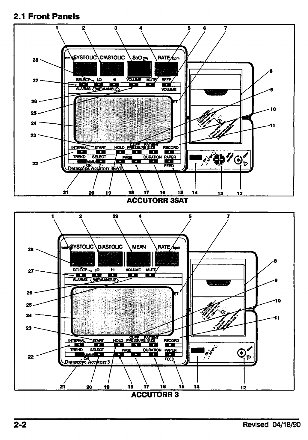
2.1
Front
Panels
18 17
ACCUTORR
16
15
14
J3
12.
3SAT
2-2
ACCUTORR
3
Revised
04/18/90
Page 15
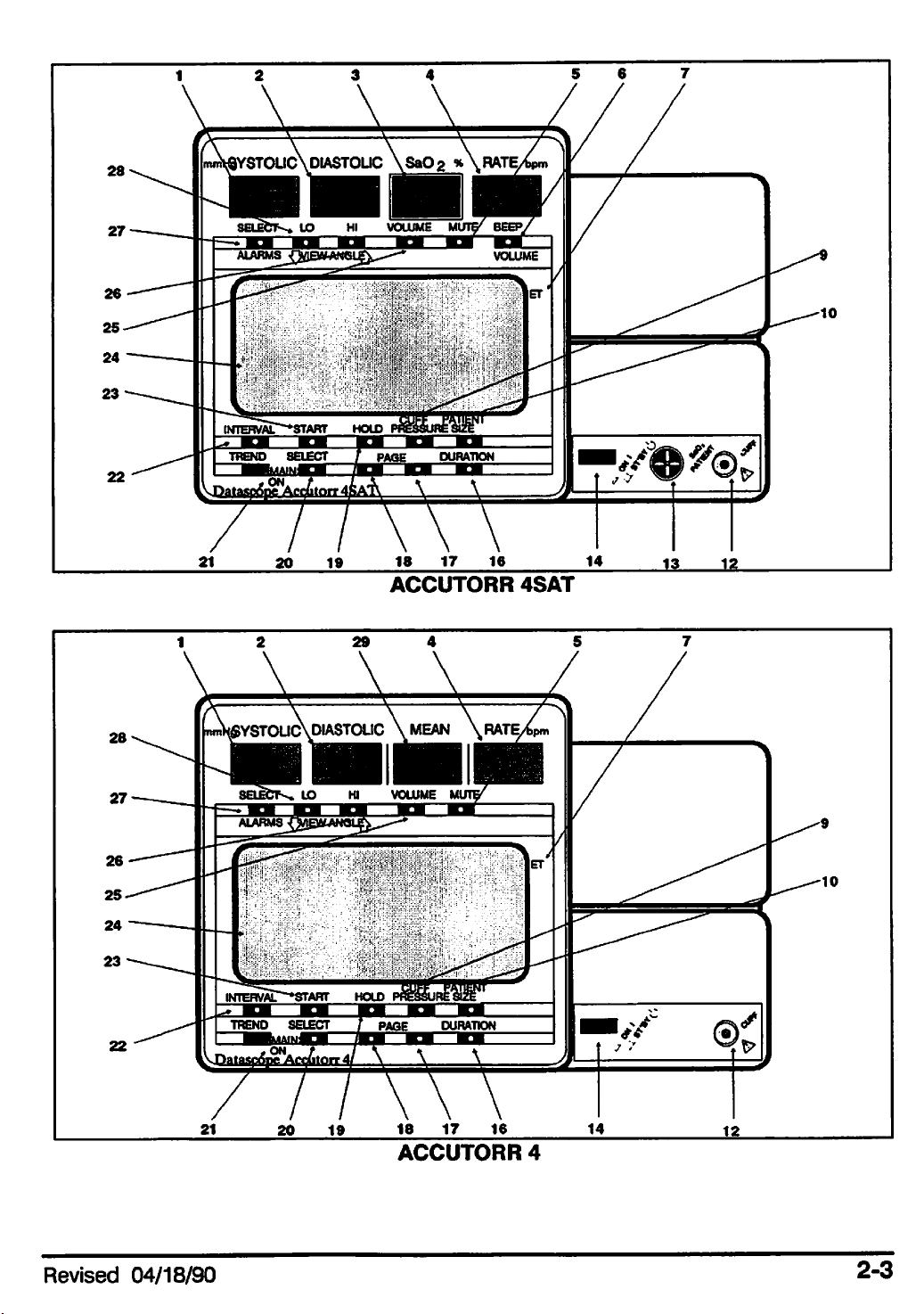
ACCUTORR
4SAT
Revised
04/18/90
ACCUTORR
4
2-3
Page 16
1.
2.
3.
4.
5.
6.
7.
8.
9.
1.
Systolic
-
Systolic
-
Diastolic
-
Sa02%
-
Rate
-
Mute
-
Beep
-
ET
-
Printer
-
Cuff
bpm
(Alarm)
Volume
Elapsed
Module
Pressure
- A 3-digit,
(Sa02]
Time
amber
10.
•-
Patient
11.
•
-
Record
12.
•
•
Cuff
13.
•
-
Sa02
14.
••
ON/STBY
15.
•
-
Paper
16.
•- Duration (Trend)
17.
••
PageDown
.
18.
19.
PageUp
•
•-
Hold
Size
Patient
Feed
LEDdisplay indicating systolic
20.
21.
22.
23.
24.
25.
26.
27.
28.
29.
pressure
••
Select
•
•
Mains
•
•
Interval
-
Start
•
•
•
LCD
••
Volume
--
Hi
(Alarm Limit)
-
•
Select
-• Lo
(Alarm
•
Mean
-
in mmHg.
(Trend)
On
Display
(Alarm)
(Alarm)
Limit)
2. Diastolic - A 3-digit,
3.
4.
SaOa
Heart
- A 3-digit,
Rate
- A 3-digit,
amber
(bpm).
5.
Mute
next
minutes. MUTE
twice
6.
SaOo
select
7. ET
8. Printer
9.
Cuff
(Alarm) -
Cancels
measurement
does
within3seconds
Beep
the
(Elapsed
Volume
volumeofthe
Time)
Module-Usedtoproduce
Pressure
-
Selects
amber
LED
display indicating diastolic
LEDdisplay indicating saturated oxygen in %.
amber
cycle.
not
all
- (ACCUTORR3SAT
continuous
- Displays
LED display indicating
the
volume of
Cancels
affect
alarms
the
will
the
the
volume of
flashing digitsormessages.
be
Sa02
the
amount of time since
a "hard copy" of
the
initial
NIBP
NIBP
muted
and
beep.
cuff
heart
audible alarm until
the
Sa02 audible alarm for two
for2minutes.
ACCUTORR4SAT only)
the
the
data
inflation
values.
pressure
in mmHg.
rateinbeats
the
IfMUTE is
last
NIBP
obtained
per
minute
endofthe
pressed
Used
to
measurement.
by
the
monitor.
10.
11.
Patient
The
Record
Size-Selects
selection is displayed in
- (ACCUTORR 3
selectedordesignated
12. NIBP
monitor.
13.
SaOs
the
2-4
Connector
Patient
monitor.
the
interval timed
- A
connector
Connector
desired
the
and
operating mode,
LCDwindow.
ACCUTORR3 SATonly)
data.
usedtoattach
- A
connector
usedtoattach
ADULT/CHILDorNEONATE.
the
Usedtobegin
NIBP cuff
the
Sa02
assemblytothe
the
Sensor
Revised
printing of
assembly
08/01/90
to
Page 17
14.
ON/ST'BY
intoaST'BY
15.
Paper
the
Feed
recorder.
Switch
mode.
- A
push-button
- (ACCUTORR 3
switch
and
ACCUTORR 3 SAT only)
usedtoturn
the
monitor ONorto
Usedtofeed
place
paper
it
into
16. Duration (Trend) -
scales
clear
17.
Page
18.
Page
19.
Hold
(The "hold
urement
20.
Select
order
21.
Mains
state.
22.
Interval
urements.
are
1-, 2-, 4-, 8-, 12-,or24-hours. Hold this key
the
trended
Down-Usedtoscroll
Up -
Usedtoscroll
- A
touch
cycle
switch
mode"
alreadyinprogress
(Trend)-Selects
(ListTrend, NIBP
On
- A
green
- A
touch
INTERVALS ARE:
urement immediately after
10-, 15-, 20-,
30-,
Selects
memory.
time
through
through
used
to
place
suspendsaseries
the
desired
switch
OFF
45-,
Graphic
LED
used
(only
60
and
Trend,
used
to
to
appliestothe
the
other
120-minutes.
scales
select
for graphically
the
tabularorgraphic
the
tabularorgraphic
the
measurement
of timed
(deflates cuff)).
trend
Sa02
notify
the
the
measurements
and
Graphic Trend,
operatorofthe
automatic
Interval feature),
trended
down
for
data.
three
displays.
displays.
cycle
into a
or
terminatesameas
waveform display in
Sa02
monitor's
timer
intervals
Continuous
Available time
seconds
"hold
the
mode."
following
Waveform).
mains
for
NIBP
(one
on/off
for a maximum period of five minutes), 1-, 2.5-, 5-,
to
meas
meas
At
power
pressed.
up
CONTINUOUS is
of five minutes. At
five
minutes.
23.
Start-
sequence.
24. LCD
able
form;
waveform.
Revised
Usedtobegin
Display
Sa02,
trended
08/01/90
the
timer
interval
one
measurement
the
endofthe
an
will
NIBP
- A liquid crystal display
measurements
in a tabular form;
Sa02/heart rate
be
as
last
immediately after
five minutes a
measurement
used
data
in graphic form;
set,
but
measurement
sequence
to exhibit
trended
will
not
be
the
other
ortobegin
NIBR
heart
NIBP/heart
and
when
activated
until START is
for a maximum period
willbetaken
the
rate,
rate
data
available,
once
interval timer
and
when
in graphic
an
Sa02
every
avail
2-5
Page 18
25.
Volume
(OFF,
Mode.
marker
disabled,
(Alarm) -
LO,
MED,
See
Section 3.4.12.Ifthe
will
appearinthe
then
HI).
no
Sets
The
marker
the
volume of the audible alarm to
OFF selection maybedisabled in
alarm OFF selection is activated, a rectangular
upper
will
left
appear.
cornerofthe
VOLUME
one
offour settings
the
User Configuration
window.Ifthe
alarm
OFF
is
26.HILimit (Alarm) - When in
selected parameter. The high alarm
is highlighted in
play. When in
27.
Select
sure,
mean
If
this key is
low
limit,
28. LO
29.
Limit
selected
is highlighted in
play. When in
Mean
- A 3-digit,
measurement
ment cycle
(Alarm) - Selects
which
(Alarm)-Wheninthe
parameter.
the
window superimposed in
the
normal mode,
pressure,
pressed
the
cycle
the
for 3
willbesetto85.
The
the
window
normal
amber
the
mean
an
heart
seconds
low alarm
mode,
LEDdisplay indicating
mean
pressure
the
Alarm
Set
limit
changes
Mode,
can only be
sets
the
trend display
the
high alarm
set
for
the
area
the view angle (contrast).
limit
for
alarm parameterthat
on
the
alarm parameter, i.e., systolic pressure, diastolic
rate,oroptional
the
Alarm
limit
superimposedinthe
changes
pressure
represents
Sa02.
alarm limits
Set
Mode,
can
only
the
view angle (contrast).
mean
represents
mean
arterial
willbesettoOFF
sets
the
low alarm limitfor
be
set
for
the
trend display
pressure
the
cuff
area
pressure.
pressure.
except
alarm
in mmHg. During a
parameter
on
the
After a
the
LCDdis
pres
for
Sa02
the
that
LCD dis
measure
2-6
Revised
08/01/90
Page 19
2.2
Rear
Panel
30.
Battery
31. Potential
the
ground
ACCUTORR
32.
Power
33.
Power
line
cord.
34.
Mains
35.
Datasette
unit.
Input
Input
cord
Power
Compartment
Equalization
potential
3/4.
Label
between
- Identifies
Module
receptacle,
Switch
Module
Port
ALL
-
Contains
the
Lug-(Equipotential
- (Line
fuse
- A
other
Cord
holder,
switch
hospital
the
power input.
Receptacle,
and
usedtoactasthe
- An input slot
UNITS
optional
rechargeable
Post)
equipment
Fuse
voltage
selector
usedtoconnect
battery.
- A
connector
and
the
used
Datascope
to equalize
Holder, Voltage Selector) - A
for mating with a
line
power
the
(mains)
software
detachable
disconnect.
moduletothe
line
2-7
Page 20

36.
RS232
al high
Connector* (Data Out) - A25-pin D-typeconnector used to provide addition
speed
channels
of non-isolated devices to
leakagetoexceed
for Datascope peripheral communications. Note: Connection
the
the
specifications.
RS232 Connector on this unit may
cause
chassis
Interface
37.
with only
38. Serial
rating of
39.
Leakage
ing only to 220V units.
Connector*
Datascope
Number
the
unit.
Label (for220V only) - A label used to identify leakage information pertain
equipment.
Label
- A 24-pin IEEE
#488-1978
type
receptacle
- Identifies model number, serial number,
fuse
used
type,
to interface
and
AC
* Before using
for
assistance.
2-8
the
communication connectors, contact authorized service personnel
Revised 02/16/90
Page 21

3.0
OPERATION
This section of
the
Operating Instructions provides general guidelines
and
step-by-
step instructions for the proper operation of the monitor. Numbers in parentheses
identify the displays
INDICATORS.
Abbrievated
CAUTION: Only
familiar
structions
A.
with
this
in
the
Setting-Up
1.
Set
rear
2. If
desired,
3.
4.
5.
6.
Attach
Set
Press
Set
power
Mains
ON/ST'BY
(when appropriate)
-Patient Size (Adult/Child or Neonate)
-Alarm
-Alarm
-Sa02
Limits
Volume
Beep
-View Angle (Contrast)
and
the controls described inSection 2.0,
Operating
use
Abbrievated Operating Instructions if
product.Ifnot
remainder
Instructions
please
of
this
chapter.
continue
panel Mains Power Switch to OFF.
interface
any
peripheral equipment.
cord.
Power
Switch
Switch
Volume
to
to
the
ON.
ON.
following:
with
CONTROLS
you
the
Detailed
AND
are already
Operating
()
In
B.
Initiating
1.
Select
2. Attach cuff
3.
Select
4. Select cuff
5.
Press
6.
Press
C.
Establishing
1.
Select
2. Attach
3.
Press
D.
Recording
1.
Select
2.
Press
3.
Press
NIBP
cuff.
Measurement
hosetoNIBP
timer
interval, if
desired.
pressure,ifnecessary.
Starttobegin
Holdtosuspend
Sa02
appropriate
sensortothe
Trend
Selecttoobtain
NIBP
measurement.
(ACCUTORR
sensor.
Sa02
Information
desired
Recordtostart
trend
screen
recording function.
Record againtostop
connector
and
measurement.
3/4
SAT
connector
Sa02
or
Sa02
and
waveform,ifnecessary.
waveform
recording function.
place cuff on patient.
only)
applytothe
to
patient.
record.
Revised
12/21/89 3-1
Page 22

Detailed
3.1
Sefflng-Up
1.
Set
the
Operating
rear
panel
Instructions
MAINS
POWER SWITCH (34) OFF.
2. Check
configuration.
the
serial number label (38) and voltage indicated. Confirm proper voltage
If
the
monitor is not wired correctly, contact a Datascope Service Repre
sentativeorqualified hospital personnel.
3. Ifinterfacing with
cable
and
4. Ifadditional
Cabletothe
terface
5. Attach
MODULE (33)
use
(P/N 0012-00-0271)
the
corresponding
rear
connector
the
AC
an
adaptortodefeat
When
chassis
other
communications
panel
on
power
and
into a
compatible
between
interface
RS232
the
peripheral
cord
grounded
the
into
U-ground.
attached
leakage
currents
Datascope
the
connector
capabilities
Connector.*
instruments).
the
Datascope
(3-prong) Hospital
WARNING
to
other
*
3.2
Turning
Power
On
rear
panel
on
are
Data Out (36)
products
of
all
100
ua.
instruments,
INTERFACE CONNECTOR* (37)
the
peripheral
required,
ACCUTORR's
Grade
insure
units
(total)
attach
instruments).
attach
and
the
the
rear
AC
that
do
the
interface
RS232 Interface
corresponding
panel
receptacle.
the
not
INPUT
total
exceed
v '
Do
in
not
1.
Place
(21),
2.
Press
The
The
(initial
•
• All
•
•
NOTE:
Advisory
The
the
should
the
message
following
power
Internal
Front
The
LCD Advisory
The
Alarm
To
insure
Paneltolight up.
monitor is
rear
illuminate
front panel ON/ST'BY switch (14) to ON.
Self-Check
• Before using
for
assistance.
panel
on
"INTERNAL
items
up):
Panel
are
LEDs
Panel
Tones
proper
ready
the
for
communication connectors, contact authorized service personnel
MAINS
the
TEST
checked
function,
use
when
POWER SWITCH (34) to ON. A
front panel.
IN
PROGRESS"
during
the
watch
the
messageiserased
first 10
for all front panel LEDs
displays
seconds
from
green
on
the
LCD advisory panel.
of monitor
and
the
LCD.
LED,
the
MAINS
operation
LCD
ON
3-2
Revised 02/16/90
Page 23

If
the
self-test is
LCD:
If
anyofthese messages are displayed, the
3.4.8, LCD
not
RAM
RS232
TEST
PORT
Messages,
successful,
FAILED
FAILURE
one
of the following
for further instructions.
ROM
D.S.
monitor
messages
TEST
BUS
will
not operate. See Section
willbedisplayed on the
FAILED
FAILURE
3.3
Initial
The
following
FUNCTION
Timer
Hold
Patient
Trend
Control
initial
Interval
Size
Display
Systolic Alarm Limits
Diastolic
Mean
Rate
Alarm
Sa02
Record
Initial
Alarm
Alarm
Alarm
Volume
Beep
Cuff
Limits
Volume
Inflation
View Angle
Settings
settings are automaticallyselected at power on.
Limits
Limits
INITIAL
ON
As
OFF
As
Tabular
As
As
As
As
As
As
OFF
Adult/Child:
Neonate:
As
POWER
last
set
last
set
last
set
last
set
last
set
last
last
last
last
SETTING
UP
List
set
set
set
180
120mmHg
set
mmHg
DEFAULT
SETTINGS
OFF
OFF
Adult
Tabular
OFF
OFF
OFF
OFF
MED
LO
OFF
List
Adult/Child:
Neonate:
12
o'clock
180mmHg
120mmHg
view
nominal
3.3.1
The
during
View
view
Angle
(Contrast)
angle is changed by pressing theHI(26)
normaloperation (exceptwheninthe
Alarm
and
Set
LO
(28)
Mode).
keys at any time
Abeep is heard each
time one ofthese keys is pressed. Adouble beep is heard when the last setting has
been
NOTE:
keys are used to setthe alarm
Set
Revised
reached
TheHIand
Mode
08/01/90
will
for
not
that
LO
alter
key.
keys have a dual function. When inthe
the
view
limits.
angle.
Therefore, pressing these keys inthe
Alarm
Set Modethe
Alarms
3-3
Page 24

3.4
Operation
All
ACCUTORRmodels
automatically
also
obtain
timed
Sa02
can
be
intervals.
measurements.
initiatedto obtain
The
ACCUTORR 3 SAT
NIBP
measurements manually or by
and
ACCUTORR 4 SAT
can
3.4.1
Manual
Initiation
of
NIBP
Measurements
1. Select a pressure cuffthat is approximately 20%widerthan the diameter ofthe
on
whichitistobe
A cuff that is
rect
sizeofthe
too
directbearingon the accuracyofthe obtained
tion of
cates
design dimensions of
tions
the
cuff
the
available
of
the
Limb
Diameter
45-65
30-45
24-36
18-27
16-25
11.5-19
6-11
32-42
24-32
17-25
11-17
9-13
7-10
6-
8
American
used.
narrowfor
pressure
size
on
Datascope
(cm)
the
cuff
foragiven
the
limb
the
cuffs
Heart
Association.
Description
Cuff
Thigh*
Large Adult
Adult
Child
Small
Infant
New
Large
Adult
Child
Neonatal,
Neonatal,
Neonatal,
Neonatal,
limb
will
result in erroneously high readings. The
patient
NIBP
circumferenceofthe
cuffs for
and
Name
Child
Born
Adult
use
with
their intended
Size
3
Size
2
Size
1
Size
0
Reusable
0998-00-0003-05
0998-00-0003-02
0998-00-0003-01
0998-00-0003-03
0998-00-0003-04
0998-00-0003-06
0998-00-0003-07
has,
among
other
considerations,
measurements. Base yourselec
patient.
the
Datascope
uses
are
based
Datascope
Part
The
following
ACCUTORR.
on
recommenda
Number
Disposable
0683-07-0001-01
0683-07-0002-01
0683-07-0003-01
0683-03-0003-02
0683-03-0002-02
0683-03-0001-02
0683-03-0004-02
table
The
limb
cor
a
indi
NOTE: Disposable cuffs may
instructions.
NOTE:
folds
should
The
wrapped
The
longer timer interval
over
ding
This
* when using
standards.
3-4
Cuffs
that can
be
pressure
skin is
become moresupple as theyape and sometimesdeveloppermanent
leave
replaced.
on
too
tightly. Therefore,
sometimes
temporary markson the
the
limb may
should
a period of time. In
maybeapplied to
measure
may
affect NIBP performance
the
thigh cuff this product
fragile (i.e., on pediatrics, geriatrics, etc.) In
be
extreme
the
limb in order to cushion
be
sterilized. Refer to Chapter 4 for sterilization
not
assure
limb.
fall
to zero between
that
the
Any
cuffs
that
exhibit
measurementsifthe
cuff is properly applied.
these
considered to
cases,
decrease
the
number
of cuff inflations
a thin layer of soft roilorwebril
the
skin
and
should
will
not comply with
be
when
used
the
with caution.
AAMI
accuracy
this
effect
cuff is
cases,
cotton
a
pad
cuff is inflated.
Revised
03/11/91
Page 25

2. Attach cuff
hose
to
NIBP
Connector
(12).
NOTE: The distal
edgeofthe
cuff should be placed higher on
the
patient's arm (away
fromthe elbow) to avoid differential pressure damageto the radial nerve. Referto
tion 6.3, Precautions with Using Automatically Cycled Blood Pressure Cuffs for more
information.
3. Place the cuffat the patient's heart
be
introduced
fitted
snugly,
against the patient's skin. No
4.
Press
5. Select
secondstochange
6.Ifnecessary, Press CUFF
into
the
measurements.
with
little
or no air present
clothing
the
ON/ST'BYswitch (14) ON. Waitfor a successful self-check routine.
PATIENT
SIZE (10) - either Adult/Child or Neonate. Press key forthree
the
mode.
PRESSURE
Cuffinflation values depend on the
tion
is:
PATIENT SIZE Setting
Adult 180, 200, 220, 240, 260, 100,
Neonate
level
or an error,
To
reduce
within
additional
the
cuff.
due
to hydrostatic effect, may
errors,
the
Be sure the cuffliesdirectly
should come between the patientand the
(9)
to change the cuffpressure value.
PATIENT
Initial
120,140,40,
SIZEsetting. The
Cuff InflationValues
60,
80,100,120...mmHg
sequence
120,140,
cuff
should
cuff.
of cuff
160, 180...mmHg
infla
sec
be
7.
Press
NOTE: Inflate
START (23)tobegin
the
cuff only after proper application to
an
NIBP
measurement.
the
patient's limb. Cuff
damage can resultifthe cuff is leftunwrapped and then inflated.
The
cuff
begins to
selected value the cuff begins to
to collect oscillometric pulsations.
If
the
initial
cuff inflation is foundtobe
inflate
to the selected
slowly
cuff
pressure value.
After
deflate and the Datascope
inadequate,
the
unit retries with a higher infla
reachingthe
ACCUTORR
tion pressure (+50mmHg inthe adult mode; +30mmHg in the neonate mode).
Havethe patient remain
After
the cuff pressure drops below the diastolicpressure, the results of the measure
ment are displayed on the discrete
the
completion of
During
or after an
played on the
tions.
ELAPSED
TIME
the
NIBP
LCD
(7) indicates the amount oftime since the completion of the last meas
urement. Elapsed time is updated each minute
still
to avoid the introductionof unnecessary motion artifact.
LED
readouts. Atwo tone audible beep indicates
measurement.
measurement, one ofseveral advisory messages may be dis
window. Referto Section 3.4.8,
LCD
Messages, for their explana
until
a new measurement is made.
begins
8.Ifdesired, press
Revised
12/12/90
HOLD
(19)
to cancel a measurement.
3-5
Page 26

3.4.2 Automatic Initiation
1.
2.
Press
The
Press
INTERVAL (22) until
LCD Advisory (24)
Off,
Contin*,
START (23)tobegin
1-,
2.5-,
will
5-,
the
display
10-, 15-,
an
of
NIBP
desired
oneofthe
automatic, timed
Measurements ^
timed-interval setting is
following:
20-,
30-,
45-,
selected.
60-,or120-minutes.
measurement
sequence.
Automatic
In
the
reading of
cuff inflation
systolic
Suspension
To
suspend
cycle
To
Note:
alreadyinprogress
Press
-
resumeasuspended
-
Press
minate a
Interval
Pressing
mode, I
the
Interval
not
be
Adlustment
timer
mode,
the
systolic
pressure
+50mmHginthe
of
an
HOLD (19).
START
Press
activated until START (23) is
HOLD (19)atany
measurement
Set
Mode
the
INTERVAL key (22)
INTERVAL]
Mode
In
the
Timer
the
unit
adjusts
pressure.
display
Automatic
automatically timed
reads
Adult
(deflate cuff):
timed
Mode
NIBP
measurement
Mode
the
inflation
After
the
first
"AUTO"
and
Feature
measurement
pressure
accordingtothe
measurementinthe
and
the
inflation
+30mmHginthe
sequence
sequence:
pressureisthe
neonate
ortoendameasurement
(23).
timetopostponeascheduled
cycle already in progress.
enters
the
unit into
the
is displayed inreverse graphics on the monitor.Ifthe
when
turned
off, when
pressed.
powered
up it
will
measurement
Interval Mode.
stillbein this
timer
mode.
previous
mode,
previous
ortoter
When
in this
unit is leftin
mode,
the
but
will
Observe
Pediatrics,
Reports
blood pressure cuffs.
Blood
* A five-minute limitis
ACCUTORR
taking
one
3-6
have
been
Pressure
will
automatically switch to a five-minute
measurement
Extreme
and
made
of nerve injury occurring during
See
the
Cuffs".
placed
on
every five minutes.
CAUTION
Caution
Adults)
Continuous
Appendix, "Precautions
continuous
On
All
When
Mode.
measurements.
Patients(Neonates,
NIBPisstet
use
of automatically
when
Using Automatically Cycled
measurement
to
After five
interval cycle,
the
cycled
minutes
Revised 08/01/90
the
Page 27

3.4.3
If
the
the
SURE.
The
any
NIBP
cuff
pressureisoverpressurized,
alarm
new
toneissounded,
unit
must
measurements
Pressure
be
turned
off
are
Limit
and
and
taken.
Fail
Safe
the
the
advisoryonthe
back
on
againtoreset
cuff
will
automatically
LCD
reads
the
overpressure
venttoatmosphere,
CUFF
OVERPRES
switch
before
3.4.4
If
the
orifthe
vented
3.4.5
The
sequence.
• INTERVAL is
An
not
that
taken
with
•
The
Cuff
cuff
pressure
target
and
the
START
START
unscheduled
affect
follow
for
the
and
the
willbetakenasif
each
scheduled
INTERVAL
timed
measurementissuspended
deflation).
Inflation
pressureisnot
RETRYorUNABLETO MEASURE
and
HOLD functions
set
measurement
timing of
measurement
isset and you press
Time
does
not
attain 20mmHg within40seconds
HOLD
and
you
the
interval cycle. In
there
measurement.
reached
Functions
have
Press
is
within
the
START (23):
made.
Taking this
following effects
other
werenointerruptions.Only
cycle -
evenifthe
HOLD
or
(19):
the
another
60
message
unscheduled
words,
the
unscheduled
measurement
of
the
seconds,
will
on
then
appearinthe
the
timed
measurement
scheduled
one
measurement
measurement
cycleisstopped
start
of inflation
the
cuff is
LCD.
measurement
does
measurements
coincides
(cuff
is
•
INTERVALisset
The
HOLD
mentisbegun
the
interval
Hold
mode
minutes:
Time
10:00
10:04
10:05 Timer
10:07 Hold
10:10 Timer
Revised
08/01/90
and
you
modeiscancelled,
by
pressing
timer's
affects
Mode/Timer
Notinhold
Hold
request.
scheduled
modeisentered
START,or
Interaction
mode
requestsameasurement
mode
is exited Hold
requestsameasurement
Press
i.e.,
HOLD
the
cuff
another
measurements.
(19) a
remains
second
deflated
time:
until
measurement
For
example,
Result
Measurement
Hold
message
with
Measurementisskipped
message
Measurement
another
measure
is automatically
the
interval
taken
is
displayed
no
longer
is displayed
taken
begun
settofive
on
LCD
by
3-7
on
LCD
Page 28

3.4.6
Sequence
for
Establishing
SaO?
Sa02
ACCUTORR
1. Select
the
Guidelines for
2. Follow
3.
4.
measurements
the
information
the
The
Sa02
Press
PAGE DOWN (17) or PAGE UP (18) to
can
be
4
SAT
monitors.
appropriate
included
the
selection of a
obtained from
sensor
in
this
for
section.
sensor
the
the
patient.
are
provided in
Datascope
Base
patient application instructions provided in
waveform displaysonthe
LCD.
change
played. (The selected waveform size is remembered
5.
Press
available settings including OFF.
ing levels to maximum then
the
current volume
generated
3.4.7
Awide
3/4
SAT.
patients
BEEP
VOLUME
willbegenerated.Ifa
as
the
volumeisincreased.
Sensors
rangeofsensors
The
sensors
ranging
from
neonates
(6) to
are
cover
set
off,
the volume of
If
held
etc.Ifa
depressed,
Sa02
the
sensor
sensorisconnectedabeep
available for connectiontothe
both
short-term
to
large adults.
and
long-term monitoring
ACCUTORR 3 SAT
your selection of
the
Sensor
each
sensor
the
size of
onceithas
Sa02
beep.
the volume
been
will
the
Selection Chart.
package.
the
waveform dis
selected.)
There
are
change
is not connected, then a
will
Datascope
ACCUTORR
needs
and
sensor
eight
in increas
beep
not
be
on
the
on
at
The DIGISENSOR is intended for short-term adult monitoring.
The FLEXISENSOR SD, available in
long-term monitoring for large adults, adults, pediatrics, infants,
FLEXISENSOR
The
ear
sensor
monitoring site for
A
rangeofdisposable
They
are
available in 2 styles, butterfly (used for large adults, adults,
and
coban
Useofthe
electrical
The
tor).
contactortransferofexcessive
sensoriscomposed
The
emitter
SDisused
when
is intended for long-term adult monitoring. It is a convienient alternate
the
anesthesiologist.
bandages
(used
sensors
for infants
does
not
and
cause
of a lightemittingdiode (emitter)
discharges
two colors (wave lengths) of light into
five
differentsizes, provides both short-term
the
DIGISENSORisnot
are
available for
neonates).
any
penentration of
heattothe
use
convienient
with
the
patient.
and
and
neonates.
the
FLEXISENSOR SDs.
and
skin,
noristhere
a photodiode (detec
the
tremity (finger, toe, ear). The detector receives that amount of light not
the
bloodortissue
the
two
light
wavelengthstocompute
components.
The
ACCUTORR
and
display
then
uses
Sa02 and
the
relative
Rate
measurements. )
or
suitable.
pediatrics)
any
patient's ex
absorbed
absorbtion
and
The
by
of
3"8
Revised
09/22/89
Page 29

The
key
benefitsofthe
sensors
are:
-electrocautery
noise
(ESU) rejection
-the monitoring of restless patients
-tracking of
-rejectionofambient
-long
-can
-patient isolation
-easeofapplication
The
term
be
• Electrocautery
sensor
uninterrupted monitoring and
can
be
the
monitor, via
• Monitoring
weak
patient
resterilized (ETO sterilization - 3 times)
configuration of both
set
at any power level). This design prevents electro-surgical noise entering
peripheral pulse levels
light
comfort
and
removal
Noise
the
Restless
(ESU) Rejection
the
DIGISENSORand
absence
of false alarms during
sensor, and interfering with unit operation.
Patients
Motion artifact rejection is achieved in several ways.
1.
The
the
sensortothe
sensor
design
patient.
used
with their
recommended
the
FLEXISENSOR SD provide
the
bandages
use
of ESU (ESU
assuresasnug
fit
of
2. Light emitting diodes (LEDs) and detectors gather a strong signal from
3. Software in the ACCUTORR evaluates the
rejects noisy
4.
Wheninthe
creasing itto a maximum of 15
and
unreliable pulses.
presence
of motion,
seconds
the
during quiet periodstoobtain a fast response. This combination
of monitoring interruptions
• TrackingofWeak
and
false alarms from patient motion.
Peripheral Pulse Levels
Many patients suffer poor peripheral perfusion
The
reduced cardiac output, etc.
ACCUTORR is designed to automatically increase
shape
software adjusts
of each pulse and automatically
the
"averaging-period", in
during motion, and automatically reducing it
reduces
due
to hyothermia, hypovolemia,
the
the
patient.
number
its gaintotrack patients with poor peripheral perfusion.
• RejectionofAmbient
Light
Many monitoring situations involve high levels of ambient light, ie., operating room
lights, neonatal phototherapy, heat warmers, etc.
and
bandages
ically
measures
the
DIGISENSOR prohibits
with
sensor
bandages,
each
and
operation.
which are
contribute to
the
rejection of
corrects for high levels of ambient light.
the
interference of high levelsofambient
And
the
used
with
opague
the
material
FLEXISENSOR SD,
The
ACCUTORR Monitor, sensors,
ambient
usedinthe
light.
helps
The
monitor
The
enclosed
lightonadults
compositionofthe
keep
out
ambient
automat
design
of
light.
3-9
Page 30

•
Patient
The
FLEXISENSOR SD line is designed to slip into a disposable
(butterfly
anatomy.
A.
Sensor
Comfort
and
coban)
Selection
which conform comfortably
and
Application
and
safely to
bandage
the
particular patient's
of two styles
Selection of a specific
and
expected
monitoring duration.
General guidelines for
Chart,
Instructions for
package.
B.
1. Align
(13)
which
Sensor
on
the
follows.
the
Connection
the
cable
ACCUTORR 3SAT/4SAT.
sensorisbased
the
selection of a
application of a
to
connector
2. Push the cable connector
cable
TO
WHEN
C.
connectorissecurely
OBTAIN MAXIMUM CABLE
ATTACHING
Sensor
Inspection
TO
OR
on the patient's age, sex, physical condition,
sensor
sensor
the
ACCUTORR
on
the
sensor
into
the Sa02 Patient Connector
in place.
USE,
DISCONNECTING
to a patient
assembly with
DO NOT TWIST
are
provided in
3SAT/4SAT
FROM
are
provided in
the
THE
CABLE
THE
the
Sensor
each
Sa02
ACCUTORR
Patient
(13).
Confirm
CONNECTOR
Selection
sensor
Connector
that the
3SAT/4SAT.
Before
use,
always inspect
abrasions. Do not
good
For
-Do not
Between
accessory
using
-Avoid running
-Avoid
-Watch for
3-10
long
For
accessory
working
sensor
drop
use,
pouch,orcoil
the
optional
strong
cracksinthe
sensor.
life:
on
the
store
part
any
pulls
sensors,
use
the
sensor,
floor, or give other
the
sensorsinthe
the
sensor
cable
number
cart,
on
the
retainer.
information
bed,orany
sensor
DIGISENSOR housing.
cables,
cable or connector if
sharp
and
connectors for
shockstothe
damage,
damaged.
sensor(s).
optional FLEXISENSOR SD Organizer,
cable
piece of
and
store
see
Section 5.2, "Optional Accessories".
equipment
on
the
sideofthe
over
the
sensor
cable (10 lbs/4kg).
ie.,
cuts
Replace with a
ACCUTORR
cable.
and
Page 31

-Watch for
D.
Sensor
For
the
BEST
cracks,
Performance
performance
cuts,
rips, fogging,orsigns
of all
Datascope
of moisture in
sensors:
the
FLEXISENSOR SD.
-DO NOT PLACE
sure
cuff in
tremity
place.
may
FLEXISENSORSD is
posite
-Encourage
the
siteofthe
any
sensor
Placementofan
obstruct
normal
placed
arterial
the
patienttoremain still. Patient motion
mance.Ifit is not possible for
on
the
FLEXISENSOR SD to
DIGISENSOR.
-Check
for
culation
If
necessary,
tions
NOTE:
-Placement of
tificial
signal,
FLEXISENSORSD if
the
the
sensor
indications
impairment.
occur,
immediately
Check
remove
the
site
daily
of
skin
abrasions,
Check
and
reapply
remove
the
sensor
site
DIGISENSOR may
nails (over 1/4" long). Incorrect placement
and
therefore
fingernails interfere with
compromise
the
sensor
the
on
an
extremity with
arterial
blood
on
catheterorblood
assure
flow.
that
same
the
patient to remain
good
on
adults
sensor
the
sensor
the
the
sensor
more
frequently on infant
be
catheter
False
extremity.
adhesion, or
and
displacement,
site
sensor.Ifanyofthe
difficult on patients with long fingernails or ar
and
an
or
pulse
pressure
rate
still,
every4hours
every4hoursifthe
find
an
can
performance. Selectanalternate site (toe)oruse
can
notbeplaced
on
acquisition of a reliable signal.
arterial
blood
Place
may
catheter
pressure
information
the
cuff.
affect
replace
change
on
sensor
above
or
blood
cuff
on
may
result if
sensor
the
the
the
neonatal
on
sensor's
sensor
site of
the
bandage
the
patients
damage,
ear
clipisused.
mentioned indica
alternate site.
and
active pateints.
also
reduce
the
patient's finger correctly or if
the
acquired
pres
an
ex
limb
perfor
or
cir
sensor
the
op
a
-Use of
Pressure
damagetothe
reposition
the
DIGISENSOR is not recommended for long-term monitoring (4-6 hours).
from
the
spring mechanism on the DIGISENSOR may
finger/toe
the
DIGISENSOR every 4-6 hours to a different site (finger/toe) or
used.
For monitoring situations exceeding 4-6 hours, either
FLEXISENSORSD with its appropriate
-Do
not
can
sure
over-tighten
affect
can
Sa02
also
result in
the
readings
pressure
sensor
and
bandages.
may
reduce
necrosis
bandage.
Excessive
readings below
and
other sking
pressure
true
damage.
cause
on
the
Sa02.
minor skin
use
a
monitoring site
Excessive
pres
3-11
Page 32

E.
ACCUTORR
Sensor
Selection
Chart
Patient Group
SensorType
Large Adult
Adult (A)
Pediatric (P)
Infant
(1)
Neonate
(N)
Adult Ear (AE)
(LA)
Approximate
Patient
Weight kg/lbs
>80kg/
>176
lbs
30-90kg/
66-198
lbs
10-40kg/
22
-88
lbs
4.5-10kg/
10-22
lbs
Upto 5kg/
Upto 11 lbs
> 40kg/
>88
lbs
Whereto
be
used
Fingers,
Toes
Fingers,
Toes
Fingers,
Toes
Feet, Palms,
Big
Toes
Feet,
Palms,
Heel,
Calf
Adult
Ear
Long or
Short
Term
Monitoring
Long&
Short
Term
Long&
Short
Term
Long&
Short
Term
Long&
Short
Term
Long &
Short
Term
Long&
Short
Term
ESIS
Included
Included
Included
Included
Included
Included
Re
usable
Yes
Up
20
Yes
Uptp
20
uses
Yes
Up
20
uses
Yes
Up
20
uses
Yes
Up
20
uses
Yes
Up
20
uses
to
uses
to
to
to
to
Bandage
Type
Adhesive,
Disposable
Adhesive,
Disposable
Adhesive,
Disposable
Non-Adhesive*,
Disposable
Non-Adhesive*,
Disposable
N/A
Part
Numbers**
Sensors Bandages
0998-00-0076-03
0998-00-0076-02
0998-00-0076-01
0998-00-0074-03
0998-00-0074-02
0998-00-0074-01
0683-00-0409-01
0683-00-0409-02
0683-00-0409-03
0683-00-0415
0683-00-0440
N/A
DIGISENSOR
*Non-adhesive bandagesarerecommended
40 +kg/
90+lbs
Fingers,
Toes
for
premature
Short
**See Accessories, Chapter 5, for more detailed information.
J
Term
Included
infantstominimize
Yes
6-
months
prenatal
N/A
skindamage.
0998-00-0088-02
N/A
Page 33

3.4.8
LCD
Messages
The following
cycle. The
messages
messages
Monitor Operation,
A.
NIBP
Measurement
Message
RETRY-MOTION
RETRY-PUMP
CUFF
RETRY
OVERPRESSURE
HIGHER
may be displayed on the
are divided intothree major categories:
and
Sa02.
Messages
fie_as_o_n
ARTIFACT
Too
much
Cuff
not
measure
Cuff
pressure
preset
motion
inflated
patient's
trip point (330mmHg).
Measurement
artifact.
enough
pressure.
exceeds
cycle
long or no pulsations
dectected.
LCD
too
during a
to
the
NIBP
NIBP
measurement
Measurement,
Response
Unit
begins
measurement
the
cuff
Unit
begins
measurement
the
cuff
Cuff
vents
a retry
after venting
for5seconds.
a retry
after venting
for5seconds.
and
remains
vented. Cycle power to
reset
The
measurement
the
this
condition
alarm
for5seconds.
Unit
beings
cuff
for5seconds.
tone
a retry
sounds
after
venting
UNABLE
B.
Monitor
TO
The following
Message.
LOW
INTERNAL
PROGRESS
RAM
ROM
BATTERY
TEST
TEST
TEST
MEASURE
Operation
messages
IN
FAILED
FAILED
Unit
complete
measurement
attempts.
Messages
pertain to
Season
Battery requires
recharging.
Self
performed.
Message
unitisturned
was
Message appears
unitisturned
was
cannot
the
test
not
successfully
the
NIBP
after
four
operation ofthe monitor.
is being
appears
successful.
off.
until
Self
test
until
off.
Self
test
not
successful.
Alarm
for
five
tone
seconds.
sounds
problem.
Response
Recharge/Replace
battery.
See
Section 4.3.
Waitfor completion
of
self-test.
Power
Power
See
cycle
unit.
cycle unit.
Section
Correct
3.2.
Revised
03/13/91
3-13
Page 34

CHKSUM
FAIL
Message appears
unitisturned
test
was
not
off.
successful.
until
Self
Power
cycle
unit.
OFFSET
PRINTER
ERROR
ERROR
C.
SaOg
The
following
Message
NO
SENSOR
SENSOR
FAIL
FAILURE
ON
DSB
ON
RS232
Messages
messages
OFF
Message appears
unitisturned
test
was
Message
problem
recorder
Message
collision
the
Datascope Serial Bus.
Message
collision
the
RS232C
pertaintoSa02
Reason
Sensor
to
Sensor
not
ACCUTORR.
not
to patient.
off.
not
successful.
indicates a
with
the
mechanism.
indicates a
or
data
error
indicates a
or
data
error
Bus.
Operation.
connected
connected
until
Self
on
on
Power
cycle
Message
the
situation
Message
a
successful
Message
a
successful
Response
Connect
Connect
unit.
remains
is
until
corrected.
remains until
transmission.
remains until
transmission.
sensor
if
desired.
sensortopatient.
INTERFERENCE
PULSE
WEAK
NO
PR
PR
SA02
CHECK
FILTER
SEARCH
PULSE
PULSE
UNDER
OVER
UNCAL
30
250
SENSOR
FAIL
Patient
motion.
ACCUTORR establishing
patient pulse level.
Low patient pulse
amplitude.
Patient pulse
detected.
Pulse
rate
not
below
operating limits.
Pulse
rate
above
operating limits.
Sa02
value
below
specified accuracy.
Sensor
incorrectly
applied. Defective
sensor.
System
unsuccessful.
self
test
was
Wait
for
motion
to
Wait or reposition
Check
Check
Check
Power
patient.
patient.
sensor
cycle
site.
unit.
end.
sensor.
3-14
Revised
03/13/91
Page 35

3.4.9
The
diastolic
A.
1.
desired alarm parameter. The alarm
Alarms
Datascope
pressure,
Setting
Press
ALARMS
and
Indicators
ACCUTORR provides high
Alarm
mean
Limits
pressure,
SELECT (27) to activate
heart rate,
the
limits
for each parameter
and
low alarm limitsfor systolic pressure,
and
Sa02*.
ALARM
SET MODE
dow superimposed on the trend display. Continue to press
cycle through the availablealarm parameters.
ting the alarm
limits
once
you
are
inthe
ALARM
Thirty
SET
seconds is allowed to begin
MODE.
andtochoose
are
displayed ina win
ALARMS
SELECT
(27)
set
a
to
NOTE: Pressing
of
the
alarm limits.
to
85.
11:44
Alarm
—
Window
4.
Press
VOLUME
and
SiflQjtSQj
HR:
50-130
10:56
10:57
10:57
11:03
11:12*
OFF
holding
All
limits
MAP=
TT8"
123
119
126
107
106
(25) until
the
ALARMS
SELECT key for 3
willbesettoOFF
91
D:
50-100
^82"
83
82
83
73
75
180mm
the
desired alarm
W
93
89
95
86
91
MED
SAT:
M:
70-OFF
73
75
74
71
65
ADULT
except
40-100
tone
for
1
MIN
"SET
99
99
98
98
98
levelfor systolic
tolic pressure, mean pressure, and heart rate is achieved
The OFF selection may
section 3.4.12.Ifthe
pearinthe
the
alarm
upper
left
OFFisdisabled,
be
disabled or activated in
the
User Configuration Mode,
alarm OFF selection is activated, a rectangular
cornerofthe
then
VOLUME
no
marker
window.
will
appear.
If
seconds
Sa02
Low, which
2.
Press
the
desired
value for
limitdisplays.
tion
3.4.9,
Limits,
high alarm limits.
3.
Press
the
desired
value
limitdisplays.
tion
3.4.9,
Limits,
lo
alarm
(off,
low,
ED
Mi
Activated
will
cancel all
will
be
set
HI (26) until
numerical
the
high alarm
See
Sec
B,
Alarm
for
the
available
LO (28) until
numerical
for
the
low
alarm
See Sec
B,
Alarm
for
the
available
limits.
pressure,
dias
medium, or high).
see
marker
will
MED
ap-
Disabled
5. If
you
VOLUME
6.Ifdesired,
ment.
Notes:
can
* if
Revised
The
1. An NIBP
not
set
equipped
08/01/90
are
using
(6) until
press
Sa02
the
an
ACCUTORR 3 SATor an ACCUTORR 4 SAT,
the
desired
MUTE (5) to silence
alarm
tone
measurement
will
alarm
be
tone
muted
can
level for
the
for
be
taken
alarm
two
alarm limits while printing data. 3.
Sa02
tone
minutes.
while
All
is achieved (low,
for
the
current
setting
alarms
the
alarm
disable
press
BEEP
etc.).
NIBP
measure
limits. 2. You
while being
set.
3-15
Page 36

B.
Alarm
The
mean
Limits
following
pressure,
chart
heart
defines
rate,
the
and
alarm
Sa02.
limits
for systolic pressure, diastolic pressure,
Systolic(mmHg)
Diastolic(mmHg)
Mean (mmHg)
Rate
(BPM)
Sa02
All
LO
C.
An alarm violation
sure,
The
(%)
NIBPsettings
Sa02
Alarm
incrementsinsteps
Violations
heart
following
•
The
LEDs of
• A
steady
rate,orSa02
occurs
alarm
ALARM
HIGH
Adult/Child
Off,
130-240
Off,
Off,
Off,
Off,
are
40-130
80-140
100-240
80-100
in increments of 5mmHg.
Neonate
Off,
Off,
Off,
Off,100-250
Off,
of 5% from 50-85%,
occurs
the
tone
when
values
with a
related
recognized
parameter(s)
soundsatthe
the
systolic
equalorexceed
PARAMETERS
40-130
30-100
30-100
80-100
HI
Sa02
andinsteps
pressure,
their
alarm condition:
begin to flash.
currently
selected
LO
Adult/Child
Off,
40-120
Off,
20-90
Off,
30-90
Off,
30-80
50-95
increments in
of 1% from 86-95%.
diastolic
set
pressure,
limits.
alarm volume level.
Neonate
Off,
Off,
Off,
Off,
steps
mean
20-90
30-100
30-100
30-80
50-95
of 1%.
pres
The
alarm
LCD, with
The
tone
continues
•
The
alarm violation no longer exists.
• The
•
Alarm
The
MUTEkey (5) is
mentorfor
within3seconds
Additional
Fifteen
•
•
•
An
seconds
SENSOR
NO
PULSE
CHECK
alarm
message
the
violated
Limits
two
Sa02
OFF
SENSOR
of 3
short
window
until:
minutes
will
Alarms:
after
oneofthese
beeps
appears
alarm
limits flashing in
AreChanged
pressed.
for
Sa02
mute
will
all
alarms
sound
superimposed
reverse
(if
alarm
(Alarms
limit
are
alarm violations.)
for2minutes.
messages
for 5
appears.
seconds.
over
the
trend
display
graphics.
isset outside alarming range).
muted until
the
Pressing
next NIBP
the
MUTE key twice
measure
area
on
the
3-16
Revised
08/01/90
Page 37

D.
Battery
Indicators
When a battery is installed in
the
unit a battery symbol
will
display.
"fc.
Battery
JZL
',SfrLjV,V
Symbol
When
• A LOW
the
battery
BATTERY
charge
advisory
is low
the
following
message
will
will
occur:
appear
on
the
display.
• An audio alarm consisting of a short lowtone followed by a long low
sounded
•
The
NOTE: When a battery is installed, the battery symbol
sage
display
once
recorder
even
per
will
while
minute.
be
inactive while
the
unit is running from AC power.
the
pump
motor
is running.
and
the
LOW
tone
will
BATTERY
be
mes
Revised
05/28/92
3-17
Page 38

3.4.10
Trend
The Datascope
NIBP
data,
The
data
can
trended
rate
With
is
taken
A.
1.
Data
NIBP,
data;
andagraphic
power on,
once
Operation
Numerical
trended
ACCUTORR
heart
be
presented on the
heart rate,
data
every
of
Trend
for
NIBP,
The listconsists of
Mean,
r
11:44
TIME
10:55
10:55
10:56
10:57
10:57
11:03
11:12*
HR,
and
J
Sa02.
MAP
SYS
121
118
123
119
126
107
106
rate
data,
Sa02*
display of
from
each
measurement.
Trend
List
heart rate,
the
time of
=91
DIA
\
B0
B2
I
\
B3
32
I
I
B3
73
75
can display and provide a permanent record* of trended
and
Sa02*
data; a graphic display of
data.
LCDinone
trended
Sa02
of three ways: a numerical listof
and
heart
trended
rate
NIBP
data.
and
heart
available parameter automatically accumulates. Data
and
Sa02*can
each
measurement, and values for Systolic, Diastolic,
|
MED
MAP
98
97
93
89
95
86
91
|
HR
71
76
73
75
74
71
65
:
be
1
SA02
99
98
99
99
98
98
98
presented
MIN
in a numerical list.
a.
Press
(20) until
trend
on
the
b.
Press
SELECT
the
screen
LCD.
PAGE
desired
displays
(18)toproceed
through
data
the
display of
(seven linesata
time).
UP
OFF
c. Press
PAGE
time). The display
whenanew
NOTE:
An * is placed next to the time ofthe most recent measurement. Readings
,
DOWN
will
measurement
that have violated alarm
NOTE: Pressing
the
screen
if
equipped
3-18
redraw
TREND
and
180mm
ADULT
^
(17)to go back through the display of data (seven linesat a
automatically return to the "page" that displays the current time
is
entered.
limits
are displayed in reverse graphics.
SELECTbefore a screen
begin drawing the next trend screen.
has
been
fully
updated
Revised
will
cancel
08/01/90
Page 39

2.
Graphic
Data
There
11:44
250
200
150
100
50
0
trended
are
two
MAP=86
13:22
Trend
for NIBP,
heart
typesofgraphic
Jjl
! IIIJJJJ IL(
13:52
MED
rate,
and
Sa02
can
also
displays - NIBP/Heart Rate
1
MIN
NIBP/HR
14:22
be
presented
and
Sa02/Heart
a.
Press
the
desired
displays
b.
Press
until
the
scale
data
can
1-,
2-.4-.8-,
time
scale.
in
graphic
Rate.
SELECT
trend
on
the
LCD.
DURATION (16)
desired
displays.
be
trend
Trended
displayed
12-,or24-hr.
form.
(20) until
screen
time
on
a
OFF
11:44
250
200
150
100
50
0
OFF
In
the
that
trend
scale
MAP=
1 '
13:22
examples
new
data
enters
duration is
setting,
data
180mm
NIBP
TREND
86
•I
.,
||
13:52
JOmm
14
Sa02
TREND
above
from
changed,
GRAPHIC
MED
|'- |
GRAPHIC
the
ADULT
||
SA02/HR
OW
i
ADULT
trend
the
right
the
right-hand time is held
is either displaced to
1
MIN
HI
\ls"
H
14:22
'
duration is
and
displaces
the
Note:
trend
pearstothe
current
the
c.
Sa02
HR
Press
PAGEDOWN
the
Note
a
scale
Note:
the
play,
(11)
picturetobe
one
hour.
older
The
current
datatothe
constant,
leftor pulled infrom
Between
updates
graphic
a line
right of
time
representing
accumulating
PAGE
UP (18)
(17)toshift
horizontal
that
of
If
Graphics
pressing
will
cause
Heart
0-250.
SELECT
Trend
scale.
Rate
RECORD
the
printed.
time is 14:22. Note
left.
When
but
depending
the
left.
ap
the
average.
or
is
on
is
set
for
dis
trend
the
on
the
The
for
the
the
graph
Duration
1
2hr
4hr
8hr
12
24
Revised
data
one
hr
hr
hr
update
hour
represents
08/01/90
rate varies with
mode
and
the
upto15 minutes for
average
the
duration that
data
sample over a period of time
Time
Slice
37.5
sec
1.25
min
2.5
min
5
min
7.5
min
15
min
the
(2 pixels
has
wide)
24
been
hour
selected. (37.5
mode.)
Each
as
shown below:
seconds
point
on
3-19
Page 40

B.
Clearing
1.
Press
The
LCD advisory
any
other
2.
The
monitor automatically returns to a normal operational
memory is
Trend
and
hold DURATION (16) for
message
message.)
cleared
and
The
the
alarm
alarm
reads,
tone
three
TREND
soundsatthe
tone
stops.
seconds.
CLEARED.
high volume for
(This
message
three
state
once
supercedes
seconds.
the
trend
NOTE:
3.4.11
The
record of a patient's: systolic pressures, diastolic pressures,
rates,
A.
1.Ifnecessary,
2.
Clear
Printer
DATASCOPE
and
Sa02.*
Operation
Press
RECORD (11) to enter into a continuous listrecording mode.
trend
after
ACCUTORR
of
Printerinthe
press
each
patient.
3 and the
NIBP
Trend
ACCUTORR
PAPER FEED (15) to
List
Mode
advance
3 SATprovidea permanent
the
paperinthe
mean
pressures,
printer.
trend listis printed. Subsequent measurements are also recorded. The
shows
3.
B.
1.Ifnecessary,
the
status of the recorder, CONfor continuous
Press
Operation
RECORD a
of
Printer in
press
second
PAPER
time to
the
FEED
and
blank for standby.
stop
the
recording feature.
Graphic
Trend
or
Sa02
Waveform
(15)to advance the paper inthe printer.
Mode
The
LCD
heart
entire
display
2.
LCD
3.
Press
Press
RECORD (11) to produce a permanent record of the graphic display on
trend area. The
RECORD
LCD
graphic display is frozen
until
at anytime during printingto abort the
the recording is completed.
process
NOTE: When tearing offrecording, tear at an angle to avoid
See
* if
equipped
Section
4.4, for
Paper
Replacement instructions.
3-20
pulling
the
of printing.
out excess paper.
Revised 08/01/90
Page 41

3.4.12
To
enter
1.
Press
The
unit
User-Configuration
into
the
user
configuration
PAGE DOWN (17),orPAGE UP (18),
will
display
the
following
mode:
menu:
or
both
while turning
the
power
on.
USER
CLOCK
RESTRICT
RS232C
ALARM
FACTORY
PRESSURE
EXIT
USER
Oneofthe
knownasthe
menu
"cursor".
items
(18)orPAGE DOWN (17).
CONFIGURATION
SET
MODE
PATIENT
ON/
OFF
SETTINGS
CALIBRATION
CONFIGURATION
will
be
The
When
TREND SELECT (20)toenter
describedinthe
A.
CLOCK
When
Time, 24
follows:
the
clock
hour
SET
following
MODE
set
modeisselected,
sections.
format) is displayed
SIZE
MODE
displayedinreverse
cursor
into
maybemoved up or
the
cursorisat
that
function.
the
current
on
the
LCDpanel.
graphics.
the
desired
The
function of
date
The
The
reverse
downbypressing
menu
option,
each
and
time
(Eastern
format of
menu
the
display is
graphics
PAGE UP
press
item is
Standard
is
as
CLOCK
SET
MODE
DATE xx/xx/xx (m/d/y)
The
next
cursor
is initially
parameter,
TIME
xx:xx
on
which is
the
month. Pressing
the
day,
then
PAGE UP (18) or PAGE DOWN (17) key
ting.
TREND
may
To
SELECT
be
pressed
exit
the
clock
enters
at
any
set
the
time
mode
time
during
press
thatisdisplayed
the
Revised 08/01/90
the
START key
the
year, hours,
changes
the
TREND SELECT (20) key.
clock
set
each
on
mode.
and
parametertothe
the
LCD
moves
the
cursortothe
minutes. Pressing
desired
Pressing
panel.
TREND
SELECT
the
set
3-21
Page 42

B.
RESTRICT
PATIENT
SIZE
When this
played
mode
(23) key until
the
displayed
C.
RS232C
When this
baud rate
on
menu
the
option is
selected
LCD panel. There
only", "adultorneonate
the
setting
menu
desired
option is
setting is displayed. Then
and
exit
selected
willbedisplayed on the
the
current setting for
are
three possible settings for
available", or
the
RESTRICT PATIENT SIZE
the
LCD
"neonate
current setting for
panel. There
mode
press
are
the
patient size
the
only".
the
HOLD
mode.
the
RS232C serial channel
seven
available settings for
the baud rate: 300, 600, 900,1200, 2400,4800, and 9600. Press
until
the
desired
played
D.
When this
displayed
MODE",or"eliminate
setting
ALARM
menu
on
is selected,
desired setting is displayed. Then
ting
and
exit
setting is displayed. Then
and
exit
the
RS232C
ON/OFF
option is
the
LCD panel.
the
alarm volume
the
ALARM
selected
ALARM
ON/OFF
The
OFF
can
press
the
mode.
the
current setting for
two available settings
MODE".
notbesettooff.
press
the
When
HOLD
the
Press
key (19) to enter
mode.
HOLD
"eliminate
key (19)toenter
the
ALARM
are
"allow
the
STARTkey (23) untilthe
willbedis
patient size: "adult
Press
the
START
(19) keytoenter
the
START
key (23)
the
ON/OFF
ALARM
ALARM
the
OFF
displayed
will
OFF
MODE"
dis
be
set
E.
FACTORY
SETTINGS
Selecting this menu option returns the user configuration parameters to their factory
settings.
The
factory settings
VIEW
PATIENT
RS232C
ALARM
ALARM
ALARM
ANGLE
SIZE
ON/OFF
VOLUME
LIMITS
are
displayed for 15
adult or neonate available (adult
9600
allow alarm off setting
allOFF,
12
o'clock
medium
baud
seconds
view
except
and
nominal
for
Sa02
areasfollows:
mode
LO which is
selected)
set
to 85
3-22
Revised
08/01/90
Page 43

F.
PRESSURE
The
pressure
sitivityof
three
separate
calibration
the
transducer
CALIBRATION
circuit for optimal
points.
test
modeisentered
into for
accuracy
the
and
purpose
for
checking
of adjusting
the
linearity
the
sen
at
1.
When
TEST
pressure
played
2.
optionisselected,
calibration
on
Connect
manometer
(Ifatest
cuff
chamberisnot
wrapped
ACCUTORR
the
PRESSURE
the
the
as
-x;
3/4
options
LCD
panelasfollows:
700cc
test
showninthe
around
a towel may
°na
CALIBRATION
the
menu
willbedis
chamber
figure below.
available,
T"
CONNECTOR
0=7^=0
ft_
700~ccTEST
for
the
and
an
adult
be
subsituted for
murcury column
CANISTER
PRESSURE
LOW
MID
HI
QUIT
RANGE
RANGE
RANGE
the
CALIBRATION
CALIBRATION
CALIBRATION
CALIBRATION
Pressure
The
cursor
pressing
When
the
desired
Calibration Test.)
may
the
arrow
cursor
menu
MODES
MODE
be
moved
keys.
isatthe
option,
MODE
MODE
press
TREND SELECTtoperform
that
function. Selecting QUIT
exits
the
mode.
3.
Select
range
pressure
LOW, MID,orHI
calibrationtoinflate
calibration
cuff (or calibration canister)
to
approximately
(for LOW),
MID,or250mmHg
50mmHg
1Q0mmHg(for
(for HI).
by
the
During this time
"PRESS HOLD TO VENT CUFF"
get
pressure
user
presses
tion
may
be
4. Compare the
manometer.
+/-
3mmHg
+/-
3mmHg
+/-
4mmHg
G.
EXIT
USER
the
pressure
is reached,
the
HOLD
the
key. Then
performed after
The
MEAN
calibration
display on the
for LOW RANGE
for MID RANGE
for HI RANGE
CONFIGURATION
willbedisplayed in the
will
pump
the
display
will
turn off
the
pressure
on
and
pressure
drops
the
to OmmHg.
ACCUTORR
tolerance
is
MODE
as
follows:
MEAN
window
LCD panel. After
the pressure
willbereleased
with
the reading on the
NOTE:Ifthe
call a
Section
manual.
service
and
the
will
be held
and
another calibra
unitisoutofcalibration,
representativeorsee
4,
Calibrationinthe
When this menu option is selected the unit performs the internal power-up
returnstothe
Revised
normal
08/01/90
operation
mode.
the
message
desired
until
tests
tar
the
Service
and
3-23
Page 44

3.4.13
Interfacing
The ACCUTORR maybeconnected
or
via
an
RS232-C port.
A .
DATASCOPE
This
connector
are
used
PIN#
9
12
21
24
as
defined below.
INTERFACE
is for
attachmenttothe
All
Description
Transmit/Receive
Open
Cable
Collector TTLCompatible
Shield/Chassis
Serial Data Ground (digital Ground)
Ground (analog)
to other equipment via
CONNECTOR*
Datascope Serial Bus. Pins
other pins
Serial
are
Data
Ground
open
circuit.
Signal Level
0-5V
OV
OV
OV
the
Datascope Serial Bus
9,12,
21,
and
24
NOTE: The maximum non-destructive voltage which may be applied to the
Datascope
B.
RS232
Interface
CONNECTOR*
connector
is
+/-12
volts.
This is an RS232-C port which can be connected to an external, compatible computer.
Pins 1, 2, 3, 4, 5, 7,
All
below.
other
pins
and
are
25
open
are
connected
circuit.
per
standard
RS232 definitions
as
defined
PIN#
1
2
3
4
5
7
25
NOTE:
connector
The maximum non-destructive voltagewhich may
C. InterfacingtoPersonal
The
ACCUTORR
access
patient data, alarm
Description
GND
TXD
RXD
RTS
CTS
Chassis
Transmit
Receive
RequesttoSend
Clear
SGND Signal Ground
AGND Analog
is
+/-25
volts.
allows
users
Ground/Cable
Data
Data
to
Send
Ground
Computers
with
limits,
and
properly
ACCUTORR
Signal Level
Shield
OV
RS232C
RS232C
RS232C
RS232C
OV
OV
be
applied to the RS232C
equippedpersonal computersto
operational status over a wire cable
remotely
(not supplied). Personnal computers must have RS232 serial communications
* Before using the communication connectors, contact authorized service personnel
for
assistance.
3-24
Revised
08/01/90
Page 45

capabilities with
the
following characteristics:
FORMAT:
DATA
STOP
PARITY
BAUD RATE:
Connectiontothe
connector
manual for specific wiring requirements.
BITS:
BITS:
BIT:
described
Once properly connected
ACCUTORR
face.
D.
INTERCONNECTION
by simple commands.
ASCII
8
1
none
Selectable
ACCUTORR is
above
from
in Section B. Refertothe
and
configured, the computer
OF
OTHER
User
done
See
Onlyequipment which complies
A
shouldbeconnectedtothe
removed.
Configuration
by a wire cable
connectedtothe
personal
can
request
Appendixfor details on using
EQUIPMENT
with
the relevant IECor BSsafety standards
signal
input/output
sockets
computer
data
the
when
25-pin RS232
operator's
from the
PC Inter
the
covers
are
Revised
08/01/90 3-25
Page 46

4.0
USER
4.1
Introduction
This
sectionofthe
the
user.
The
ACCUTORR
time
and
beyond
tenance
often
4.2
as
Care
MAINTENANCE
manual
3/4
Monitor is
under
that
calibration
required by local statutoryorhospital administration practice.
normal
described
and
and
Cleaning
outlines routine
designed
circumstances
in this section. However, it is
safety
checks
of
Monitor
maintenance
for stable operation
should
be
not
require technical
performedatleast
that
should
over
recommended
once
long periods of
a year,ormore
be
performed
maintenance
that
routine main
by
The monitor enclosure may
be
cleaned witha
mild
soap
and
water solution or ammoniated window cleaner. Applycleaning solution to the cloth, not directly onto the
monitor. DO NOTapply large amounts of
agentsororganic solvents.
liquid.
DO NOT
use
abrasive cleaning
To prevent scratches on the front panel display screens, blowor carefully brush dust
and
dirt particles with a soft
be
removed by using a liquid lens cleaner and a soft cloth. Do NOTwipe a dry
or
use
alcoholorchlorinated
4.3
•
Care
Daily,
and
Cleaning
check the sensors and cables forsigns of damage. Replace as required.
sponge
use
abrasive cleaning materials. Fingerprints
hydrocarbon
of
moistened
Sensors
with
solvents.
cleaner solution; or a fine, soft-
and
stains may
screen
• Check for the proper sensor connection to the pulse oximeter.
• Check for proper operation ofthe spring mechanism on the
•
The
sensors
•
Disconnect
• Clean and disinfectthe sensors.
and
mild
used
to
should
the
soap
remove
be
sensor
cleaned
from
the
before
pulse
Wipe
and
after
each
patient's
oximeter.
the patient contact area
and water solution or isopropyl alcohol. Hydrogen peroxide can be
dried
blood
on
all
accessible
surfaces.
DIGISENSOR.
use.
with
a soft cloth
• Let
CAUTION: When cleaning sensors: Do not use excessive amounts of
the
The
mum
the
sensor
sensor
DIGISENSOR
surface with a soft cloth, dampened withthe cleaning soultion.
completely dry before using.
can
be
temperatureof130°F.
sterilized with a
The
aeration
12%/88%
mixture of
temperature
ETO/Freonata maxi
mustbeless
liquid.
than
Wipe
130°F.
Referto the Operator's Manual, ofthe actual sterilization unit used, for the correct
sterilization
procedure.
Revised 07/02/90 4-1
Page 47

4.4
Sterilization
of
Sensors
The DIGISENSOR
tion
levelof80%RH
Inspect
4.5
Battery
1.
up
2.
3. Plug
4.
battery.
5. Tighten
sensors
Battery
Replacement:
Remove
and
then
To
remove
cable
Replace
Replacement
battery
out.
old
assembly,ofnew
door
screws.
can
be
sterilized by using 12% ETO/88% Freon 12 at a humidifica-
and a temperature
levelof130°F
max.
after strerilization for defects. DO NOT
and
Maintenance
compartment
battery
making
pullonplastic
sure
door
battery, into
that
plastic
by loosening
tab
and
unplug
connector
tab
is laying flat
the
use
damaged
two
screws
cable
and
assembly.
slide battery into place.
across
the
sensors.
and
pulling
front of
door
the
Battery
Duetothe
charged
Maintenance:
self-discharge characteristics of this type of battery, it is imperative
after 6to9
monthsofstorage
capacitymay occur as a resultof
83%.
(or unit not in use).Ifnot,
sulfation.
Charge retension at 20°C is6 months to
permanent
that
loss
it is
of
4-2
Revised 07/02/90
Page 48

4.6
Paper
Replacement
To obtain satisfactory recordings
the
printer. Do
Order
Replace
A. To
B.
Remove
replacement
paperasfollows: (numbers in parentheses refer to
open
not
carriage
empty
use
chemicalorwax
paper,
P/N 0683-00-0300-01.
compartment
paper
spool.
use
the
thermal type
treated
pull on carriage
paper.
doorbythe
paper
that
is compatible with
the
figures below)
top
edge
cut-out.
C. Place new paper spool inthe compartment so that the leadingedge of the paper is
coming off
D. Insert the
E.
Press
slot
(3).
NOTE:
label.
the
backofthe
edge
RECORD
of the paper intothe
FEEDto thread paper through the printer
role (1).
first
slot above the paper spool (2).
and
exit at the top
When tearing offa strip of paper, tear offinthe direction indicated on the tear
Figurel
TearLabel
Figure
2
4-3
Page 49

A7
Care
and
StorageofThermal
Chart
Paper
Thermal
fectedbystorage and
We
Long
• Storage Temperature
Keep
temperature
•
Donot store the recordings in plasticbags acetate sheet protectors, and
made
will,
•
Never
pound
Chart
Paperischemically
recommencTstoring
term
exposuretonaturalorartificial
the
recordingsina
and
humidity
Solvent
overa period of
Adhesive
from
place
and the
Reactions
petroleum
time,
Tape
adhesive tape
Chemical/Thermal
treated
handling
the
and
cool
products.
conditions.
recordingsina
Humidity
and
drv
(above
80°Fand
These
deterioratethe imageon the chart paper.
over
recordings..
papercan destroy the
and
These
filing
U.V.
area
foralonger
products
the
cabinet
sources
80%
Humidity)
emitasmall
The
reaction
permanencyofa
conditions
withinafew
maybedetrimental.
...
lasting
image
recordingisaf
are:
daysof
image.
shouldbeavoided.
x
amountofvapor
between
the adhesive com
within
Extreme
_,..,*
similar
hours.
printing.
items
which
Werecommendthatiflongterm archives are required, makea photocopyofthe
recordings as
retain acceptable image qualityfor about 5 years.
4.8
Sterilization
Disposable
4.9
Horizontal
The
ACCUTORR
viceRepresentative or
Instructions, Section 2 in
back-up.
cuffs
Under
of
Disposable
may be sterilizedifdesired. Use
to
Vertical
3/4 can be configuredina horizontal or vertical format. Contact Ser
qualified
the
normal
Configuration
hospital personnel and referto the Disassembly
Service Manual (P/N 0070-00-0221).
office
Cuffs
filing
conditions
ETO
sterilization
the recordings
procedures.
should
4-4
Revised
07/05/91
Page 50

5.0
ACCESSORIES
5.1
Standard
Operating
Service
Adult
Printer
Hose
Hose
Cable
Cable
Cable
5.2
Optional
Accessories
Instructions
Manual
Cuff
Paper
0998-00-0003-01
0683-00-0300-01
Manual
(3.5m) 0683-00-0189-80
(1.5m) 0683-00-0189-81
Assy., 3 CNDT
Assy., 3 CNDT, AC line
10'
Assy., 3 CNDT, AC line 2.5M
Accessories
DATASCOPE
Domestic
0070-00-0220
0070-00-0221
0998-00-0003-01
0683-00-0300-01
0683-00-0189-80
0683-00-0189-81
0012-25-0001
PART
UK
0070-00-0220
0070-00-0221
"
0998-00-0003-01
0998-00-0300-01
0683-00-0189-80
0683-00-0189-81
0012-25-0003
0012-25-0002
NUMBERS
In -
Service
Pressure
Thigh Cuff (45 -
Video
Cuffs:
Tape
65cm)
*
Large Adult (30 - 45cm)
Adult (24 -
Child
Small Child
Infant
New Born
36cm)
(18-27cm)
(16-25cm)
(11.5-19cm)
(6-
11cm)
Large Adult (32 - 42cm): Box of 10
Adult (24 -
Child
Pressure
Size 3
Size 2
Sizel
Size
0 (6 -
32cm):
(17-25cm):
Cuffs
(11-
17cm): Qty.
Qty.
(9-13cm):
Qty.
(7-10cm):
Qty.
8cm):
Qtv.
Box of 10
Box of 10
for
Neonates
50
Qty. 10
50
Qty. 10
50
Qty.
10
50
10
0061-00-0337
Reusable
0998-00-0003-05
0998-00-0003-02
0998-00-0003-01
0998-00-0003-03
0998-00-0003-04
0998-00-0003-06
0998-00-0003-07
Disposable
0683-07-0001-01
0683-07-0002-01
0683-07-0003-01
0683-03-0003-01
0683-03-0003-02
0683-03-0002-01
0683-03-0002-02
0683-03-0001-01
0683-03-0001-02
0683-03-0004-01
0683-03-0004-02
Revised
* when using
standards.
02/25/93
the
thigh cuffthis product
will
not comply with
AAMI
accuracy
5-1
Page 51

Pressure
Pressure
Pressure
Pressure
SENSORS
Cuff
Cuff
Cuff
Cuff
DIGISENSOR
DATASENSOR
DATASENSOR
DATASENSOR
Hose-Adult/Ped
Hose-Adult/Ped
Hose-Neonate
Hose-Neonate
reusable
w/3'
w/10'
Starter
adult
cable
cable
Kit
1.5m
3.5m
1.5m
3.5m
finger
sensor
Datascope
0683-00-0189-81
0683-00-0189-80
0683-04-0001
0683-04-0002
0998-00-0062-02
0600-00-0026-01
0600-00-0026-02
0020-00-0071-01
Part
No.
FLEXISENSOR
Starter
S.D.
GUARD
Kit-Each
sensor
bandages
and
S.D.
Series
starter
(with
exception of Adult Ear sensor)
(24/pack
Large Adult (LA)non-sterile
Adult (A)non-sterile
Pediatric (P)non-sterile
Infant
Neonate
Adult
FLEXISENSOR
(I)
(N)
Ear
(AE)*non-sterile
SD3Packs:-Contains
Large Adult (LA)non-sterile
Adult (A)non-sterile
Pediatric (P)non-sterile
Infant
Neonate
Adult
(I)
(N)
Ear
(AE)non-sterile
with
kit
includes
LA,
SENSOR
one
GUARD
instrument
A, P; 12/pack l,N)
Reusable
0998-00-0093
0998-00-0082
0998-00-0083
0998-00-0084
0998-00-0085
3
sensors
Disposable
cable,
one
package
of
the
same
Bandages
one
FLEXISENSOR
of SENSOR
Disposable
0998-00-0094
size.
0998-00-0076-06
0998-00-0076-05
0998-00-0076-04
0998-00-0074-03
0998-00-0074-02
0998-00-0074-05
SENSOR
Large
Adult (A) (3
Pediatric (P) (3
Coban
-3
boxes
Instrument
FLEXISENSOR SD
Cable
GUARD
adult
(used
of
Retainer
Bandages
(LA)(3packs
packs
of 24)
packs
of 24)
for Infants
12
Cable
Organizer
of 24)
and
Neonates)
*Adult Ear FLEXISENSOR is supplied withanear
5-2
(I)
(N):
0354-00-0017
clip
0683-00-0409-01
0683-00-0409-02
0683-00-0409-03
0683-00-0440
0012-00-0516-02
0683-00-0421
and
no
bandage.
Revised
11/10/92
Page 52

Chart
Chart
Paper,
Paper
Thermal
5-Roll
Datascope
Type (1 roll) 0683-00-0300-01
Pack,
Thermal
0683-00-0300-02
Part
No.
Anesthesia
Mobile
Wall Mount with 12"
Mobile
Mount
Stacking
ACCUTORR
ACCUTORR
ACCUTORR
Kit,
Probe
Machine
Operating
Stand
for
Assembly
Mobile
Bracket
3/4
3/4
3/4
Pole
Room
Equipment
Stand
Kits:
with
3000
with
MULTINEX
with
Other
with 12"
Stand
Equipment
Tray 0436-00-0044-01
with 12" Equipment Tray 0436-00-0045-01
Tray 0436-00-0046-01
0683-00-0429
0683-00-0430
0020-00-0060
0020-00-0062
Side
Frame Style Units 0020-00-0061
Optional Accessories A3/4 0020-00-0080
Battery Assembly 0997-00-0262
Genius Probe Covers (12,600) 0683-00-0445-01
*Adult Ear FLEXISENSOR is supplied with an
ear
clip
and
no
bandage.
Revised
01/05/93
5-3
Page 53

5.3
Stacking
Bracket
Instructions
5.3.1
3000
ACCUTORR
1. Install
or
MULTINEX.
3/4
the
shoulder screws (item3) into the outer holes on the
2. Attach the stacking plate
1/4" flat
aligning
in
place.
plate.
head
3. Place
screws
the
ACCUTORR
(item 2).
the key hole slots over the shoulder screws.
4. Install the two
Stacking
ACCUTORR
ACCUTORR
Bracket
3/4
3/4
#4-40
Kits:
with
with
with
the
3000
or
MULTINEX
(item
3/4
with
1)to the
the
ACCUTORR
stacking plate
x 5/16" pan head screws (item4) to
3000
MULTINEX
P/N
0020-00-0060
P/N
0020-00-0062
top
panel of
3/4 using the four #6-32 x
onto
the
3000orMULTINEX
Pull
foward
locking
the
rear of
the top
the
stacking
the
unit
ACCUTORR
To
3000
5-4
Monitor
3/4
Revised
09/27/90
Page 54

5.3.2
ACCUTORR
3/4
with
Existing
Units
1. Attach
using
and
screws
2.
slide
3.
the
Place
Secure
Stacking
ACCUTORR
the
four
the
the
ACCUTORR
the
(item 4).
Bracket
left
#6-32
front of
stacking
3/4
and
flat
Kit:
with
right
stacking
head
the
screws
stacking
3/4
forward into place.
bracketstothe
Other
Side
brackets
(item 3).
brackets
Frame
(items 1 & 2)tothe
under
lower unit
Stlye Units P/N
the
using
trim of
the
side
the
two
#4-40
0020-00-0061
ACCUTORR
frame
pan
style unit
head
3/4
Revised
ACCUTORR
To
Other
09/27/90
Side
3/4
Frame
Style Units
5-5
Page 55

6.0
6.1
APPENDIX
Warranty
Datascope
and
materials for a
posableorone-time
ship
and
use,
whicheverissooner.
Datascope
damage,orexpense
under
servicingorreplacing at
Datascope Distributor, any product which shall under normal
to
the
No agent, employee, or representative of Datascope Corp.
Corp.
materialsuptoadate
Corp. shall
this warranty
Company
warrants
periodofone
use
not
directlyorindirectly arising from
and
to have
that
its
products
one
be
liable for
the
buyer's
Datascope
been
defective in material or workmanship.
products
year
from
are
year
exclusive remedy
Corp's
willbefree from
the
warranted to
from
the
any
incidental, special,orconsequential loss,
option at
defectsinworkmanship
dateofpurchase
be
free from
dateofpurchase
the
use
of its products, liability
under
the
this warranty is limited to
factory oratan
use
has
except
defects
that
in workman
or
the
dis
date
of first
authorized
and
service
appear
any authority to bind
Datascope Corp. to any affirmation,representation, or warranty concerning its
products,
employee,orrepresentative shall notbeenforceable by buyer.
This warranty is expressly in
and
any affirmation, representation or warranty
lieu
of any other express or implied warranties, including
made
by any agent,
any implied warranty or merchantability or fitness, and of any other obligation on the
partofthe
Damage to any product or parts through misuse, neglect, accident, or by
non-standard
seller.
accessory
affixing
any
attachments or by any customer modification voids this war
ranty. Datascope Corp. makes no warranty whatever in regard to trade accessories,
such
being subjectto
the
warranty of their respective manufacturers.
Acondition of this warranty is that this equipment or any accessories which are
claimedtobe
Datascope Corp., Paramus,
defective
be
returned when authorized by Datascope, freight prepaid to
New
Jersey
07652.
Datascope Corp. shall not have any
responsibility in the event of loss or damage in transit.
6-1
Page 56

6.2
Indirect
Blood
Pressure
Measurements
and
Associated
Errors
Place
is not at
physiological pressure. Instead, the readings
the
patient in a supine position to obtain true physiological pressure.Ifthe
the
patient's heart level, the pressure values obtained
willbedecreased
every inch the cuff is placed above the heart level
the
every inch
pressure.
Blood
The
has
valueofthe
respecttothe
enoughtothe
6.3
Precautions
Cuffs
Reports
blood
automatically
• Position
have
pressure
weight exertion
• Avoid cuff
not
exit
cuff is placed below the heart level. This effect is
weight
and
the
and
it is this weight
weight of blood
heart. When
heart
level
with
been
made
cuffs.
cycled
placement
cuff
The
blood
support
on
affected nerves.
over
the
that
influences
depends
the
patient is supine,
so
no adjustment of
Using
of nerve injury occurring during
authors
pressure
the
limb in
that
course
Automatically
recommend
such
applies
of
on
cuffs:
a wayasto
pressure
the
ulnar
where
the
the
on
and
increased by 1.86mmHg for
these
the
on
a flat surface,
NIBP
readings
Cycled
following
minimize stretching of
the
ulnar nerve.Cuff tubing should
nerve
at
will
not reflect
by 1.86mmHg for
duetohydrostatic
blood
measurementistaken
pressure
the
armisnear
readings.
willbenecessary.
use
the
Blood
of automatically cycled
practices
elbow.
Pressure
when
and
the
with
using
cuff
true
•
Selectameasurement
deflation.
• Periodically
Cuff
Size
inspect
Using a narrow cuff gives erroneously high pressure readings.Ifa
pliedtoan
sipate
artery. On
the
obese
applied
the
patientora patient with large biceps,
pressure,
other hand, over-wrapping a slender arm gives erroneously low
interval
the
limb bearing
requiring
that
provides
the
cuff in
an
additional
adequate
venous
ordertodetect
the
pressure
drainage
venostasis.
standard
extra
tissue
and
increasetocollapse
sure readings. Too much force per unitarea is exerted. This requires less
to
collapse
Other
An
accurate
diac rhythm is very irregular. Irregular cardiac rhythm
beattobeat. This
CUTORR to
cessive
four tries,
the
artery.
Factors
determination of blood
changing
make
attemptstoobtainameasurement.
the
a measurement.
numeric
stroke
displays
pressurebythe
volume may
All
four ACCUTORR models
are
zeroed.
increase
Ifa
measurement
ACCUTORR
changes
the
the
time it
cannot
can
stroke
takes
make
be
difficult if
the
up to four
be
made
during cuff
cuff is
fat
will
ap
dis
the
pres
pressure
car
volume from
AC
suc
after
6-2
Revised 08/01/90
Page 57

6.4
Cuff
The
ACCUTORR
the
end
ment is determined
previous measurement.
of
Bleed
each
Rate
has
measurement.
and
Selection
3 independent bleed valves
The
adjusted ifnecessary, from
The
bleed rate is
pulses but no more than 40 pulses,
phases
6.5
of
User
the
measurement.
Verification
of
ACCUTORR
selection
are
detected between
of
the
set
by valve selection
Measurements
and
a larger valve to vent
bleed
the
valve
for
measured
such
the
systolic
the
each
measure
bleed rate of
that at least 8
and
diastolic
cuff at
the
Regular servicetoblood
pressure
equipment
will
help insure
Consult your service manual for appropriate information.
If
you question the accuracy of
manometer.
Auscultatory verification
See
the
Calibration
can
measurement. Apply a bell
stethoscope to touch either the patient's clothing or
6.6
PC
All
characters
checksums,
standard
8
data
1
start
1
stop
no
parity
baud
Interface
received
etc.
asynchronous
bits
bit
bit
rate
selectable
For
Other
and
detailsofthe
from
the
ACCUTORR
Section
be
made
stethoscope
The
ACCUTORR
sent
areinstandard
mode
the
User
check it (the
of
the
ACCUTORR
at the
over
same
time
the
brachial artery. Do not allow
the
ASCII format.
RS232
interface
are:
Configuration Menu
accurate
measurements.
ACCUTORR)
Service
the
ACCUTORR is taking a
Manual.
pressure cuff.
There
are
with a
no
packets,
the
At
powerupthe
ACCUTORR
Atthis point the
following
PC
ACCUTORR
executed by sending
present.
Command
Show
Show
Prompt
Revised
There
alarm
are
limits
patient information
request
08/01/90
willbesent:
Interface is
the
ACCUTORR
three
valid
ready
will
be availableto accept a command. Acommand is
a single characterwhen
the"
>" prompt is
commands:
Character
in
H
npti
iiAQ"
Notes
Assures
AC=ASCIIcode03
prompt
available
6-3
Page 58

The
ACCUTORR
mand
The
character,^
last
digit fields
a field is
this
(all
characters
will
respond to a command (except
colon
number
and
will
be
the
meaningofeach
notinuse,itwill
are printable):
thenasequence
followed
by
a carriage return
field is
be
represented
of 3 digit
dependent
by"
--".
"AC")
numbers
and
on
An
example
by displaying the com
separated
line feed.
the
particular
would look exactly like
byacomma.
The
numberof3
command.
If
>P:-,85,120,
Command
Responses:
45,
80,000,010,000,
5
The following is returned by the "Prompt request" command
The
following is returnedbythe
L:aaa,bbb,ccc,ddd,eee,fff,ggg,hhh,iii,iij
The
fields
a:
b:
Sa02
Sa02
are
as
high limit
low
follows;
limit
c: Pulse rate high limit
d:
Pulse
e:
Systolic
f:
Systolic low limit
g:
Mean
Mean
h:
i:
Diastolic high limit
j:
Diastolic low limit
rate
low
high limit
blood
blood
limit
pressure
pressure
"Show
high limit
low limit
alarm limts"
command
("AC")
("L"):
The
following is returned
by
the
P:aaa,bbbfccc,ddd,eee,fff,ggg,hhh,iii
The
fifeds
a^s02
b:
c: Systolic blood
d: Mean
e: Diastolic
•,
f:
g: Status Byte 1
h:
i:
are
Pulse
rate
blood
Status
Status
Elapsed
as
follows:
^r
blood
Byte 0
Byte 2
time
"
pressure
pressure
pressure
(see
next
(see
next page)
(see
next
(minutes)
page)
page)
since
6-4
"Show patient data"
last
NIBP
measurement
command
("P"):
Revised 08/01/90
Page 59

The
bered
shown
Status
three
as
below:
status
follows:
bytes
76543210.
0: Bit0:
Bit 1:
Bit2:Sa02
Bit 3:
Bit 4:
Bit5:Sa02
Bit6:
Bit 7:
are
Sa02
Sa02
Sa02
Sa02
Sa02
Sa02
a binary
sequence
The
meaningofeach
of flags.
Each
indicating NO SENSOR
indicating SENSOR
indicating
INTERFERENCE
OFF
indicating PULSE SEARCH
indicating PULSE LEVEL WEAK
indicating
NO
PULSE
indicating CHECK SENSOR SITE
indicating PULSE RATE UNDER
bit in
byte
the
contains
status
' ^
30
BPM
8 bits
num
bytesisas.
J
:
"'
Status
Status
6.7
1: BitO:
Bit
Bit
Bit
Bit4:
Bit
Bit
Bit
1:
2:
3:
5:
6:
7:
Sa02
Sa02
Sa02
Sa02
Sa02
Sa02
Sa02
Sa02
indicating PULSE
UNCALIBRATED
ALARM
RAM
OVERLAPPED
TEST
RATE
FAILURE
ROM TEST FAILURE T
OFFSET
FILTER
SYSTEM
MISMATCH
MISMATCH
TEST
IN
PROGRESS
2: BitO: NIBPindicating CUFF OVERPRESSURE
References
Bit 1: NIBP indicating
Bit2thru
7:
Not
used
MOTION
ARTIFACT
OVER 250 BPM
The following bibliography provides several articles and books of interest on pujs©, 3 ,
oximetry
and issues affecting
Sa02
accuracy (carboxyhemoglobin, methemoglobin,
dyes, variation incalibration of algorithmsbetween manufacturers, and excessive sen
sor
pressure).
Recommendations
for Human
Blood
Pressure
Determination
Sphygmomanometers. American Heart Association.
Clancy, Fred. FactorsAffecting
Pressure Measurements.
HazardofAutomatic Non-Invasive
718,1981.
Added
08/01/90
Journal
Correlation
Between Directand Indirect
of Clinical Engineering,
Blood
Pressure Monitoring. Anesthesiology 55:717-
by
3:49,1978.
Arterial
~
Blood
6.5
Page 60

Sy, W.P.
Pressure
Ulnar
Cuff.
Nerve Palsy Possibly Related to Use of Automatically Cycled Blood /m*
Anesthesia
and
Analgesia
60:687-688,
September
1981.
Harrison, G., G. Roth,
culation, 22:419,
Harrington,
sure Measurements., CVP, pg. 40-44,
Hanning,
Operative,
Hay,
William
BOC Health Care,
Jennis, Michael S.
the
Assessment
28
pp.
D.
Disparities Between Direct and Indirect ArterialSystolic Blood Pres
CD.
Oximetry
and
Critical Care). Ohmeda, BOC Health Care, 1985, Form
W. Jr. Application ofPulse Oximetry in Neonatal Medicine. Ohmeda,
of Oxygenation in Newborn
Nelson, Cynthia M., Everett N. Murphy,
cal
UseofPulse Oximetry to Determine Oxygen Prescriptions forPatients with
Hypoxemia. Respiratory Care, 31:8, August 1986,673-80 pp.
and
September
and
1986,1-13
and
Joyce
E. Hines. Bilateral Indirect
1960.
August/September
and
DirectArterial Pressure. Cir
1978.
Anesthetic Practice (Pre-Operativef lntra-Operativet Post-
#8601M.
pp.
L. Peabody. Pulse Oximetry:An Alternative
Infants.
Pediatrics.79:4,
April
Method
1987, 524-
JamesK.Bradley, and RobertH.Durie. Clini
for
Payne, J.P., and J.W. Severinghaus, editors. Pulse Oximetry. London: Springer-Ver-
lag.
1986.
Rasanen,
sions
change.
Jukka,
and
Oxyhemoglobin Saturations in the
CriticalCare Medicine, 15:11,1058-51 pp.
John
B. Downs, Donald J. Malec, Kenneth J.
Oates.
AssessmentofPulmonary
Oxygen Ten
Gas
Ex
and
Scheller, MS
Pulse Oximetry Readings. Anesthesiology, 65:3A,
Sidi,
A.,
W.R.
Indocyanine Green,
Pulse Oximetry.
R.J. Unger. The InfluenceofIntravenously Administered
Rush,
D.A. Paulis, N.
and
Methylene Blueofthe MeasurementofOxygen Saturation
Anesthesiology,
Gravenstein,
65:3A,
September
September
R.F. Davis. The EffectofFluorescein,
1986,
1986, A161 pp.
A132
pp.
Toledo, LauraWorthington. Pulse Oximetry: ClinicalImplications in the
of
Post
Anesthesia
Nursing, 2:1, February
1987,12-17
pp.
Dyes
PACU.
on
by
Journal
6-6
Added
08/01/90
Page 61

Corp.*58a'Wlnters
TWX#710-990-6630 Telex 7109906630
Avenue,P.O.
Box5•Paramus,
N.J.
07653-0005;
U.S.A.
•Tel.
(201)
265-8800
•
B;V.•Drs.
Telephone
W. van Royenstraat 8 •
31-3495-44911 • Fax 31-3495-34280
3871
AN Hoevelaken •
P.O.
Box26:*3870 CA Hoevelaken
Printed
in U.S.A.
•The
Netherlands •
0070-00-0220
 Loading...