

Page 1
CUSTOMER SUPPORT
Dataram's Technical Support Program goes beyond the lifetime warranty,
routine calls and questions. As memory specialists since 1967, we want
to provide the most comprehensive level of service and support in the
industry.
Our Customer Support representatives can answer your questions and
give you information on system/memory configurations, upgrade options,
product specifications, compatibility and other technical topics or issues.
In Europe:
+45 70 212 217 (Phone)
+45 70 212 211 (FAX)
eusupport@dataram.com (E-mail)
In the U.S.A. and all other countries:
800-599-0071 (Toll Free)
609-799-0071 (Phone)
609-799-6734 (FAX)
usasupport@dataram.com (E-mail)
If a Dataram memory board does not function properly we will issue a
Return Material Authorization number (RMA#) for the return of the
defective module(s) and express ship a repair or replacement to you at
no charge.
P/N 06674 D
DRS280 and DRS880 MEMORY
INSTALLATION INSTRUCTIONS
Sun Fire V480/V490, V880z, and V880/V890:
Note: Refer to your system owner’s manual for detailed instructions and be
sure to follow all static and safety precautions.
• The Sun Fire V480/V490 supports 1 to 2 CPU/Memory Cards.
• The Sun Fire V880z supports 1 to 3 CPU/Memory Cards.
• The Sun Fire V880/V890 supports 1 to 4 CPU/Memory Cards.
• Each CPU/Memory Card contains 16 DIMM slots organized into
groups of four. The four groups are designated A0, A1, B0, and B1.
• DIMMs must be added in sets of four identical modules within the
same group.
• Each CPU/Memory Card has a maximum memory capacity of 32GB.
• Older systems require OBP 4.13.2 and POST 4.13.0 versions or
grater for configurations exceeding 24GB per CPU/Memory Card.
• CPU/Memory Cards with part number 501-5818-05 must have had
the DC-to-DC Converters replaced per WO_23160.
P/N 06674 D
Page 2
MEMORY INSTALLATION
g
y
g
y
Note: Refer to your system owner’s manual for detailed instructions.
Caution: System parts are sensitive to electrostatic discharge and can be
damaged by the static charge you may carry. You should wear a
rounded wrist strap, if you have one.
MEMORY INSTALLATION
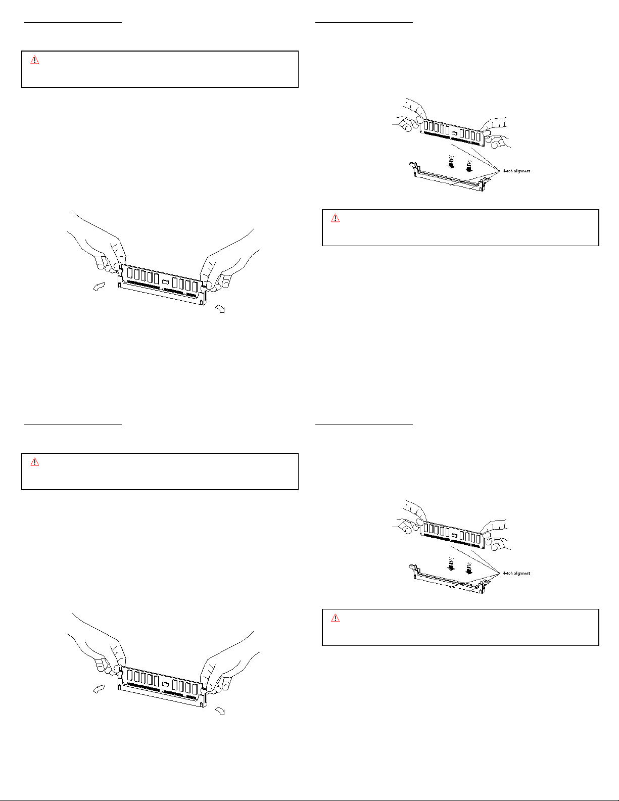
6. Position a module over the slot so that the alignment notches on the
DIMM match the notches on the connector.
7. Press firmly on both top ends of the module, applying equal pressure
until the module snaps into place. Lock the module in the socket by
pushing up on the ejector levers until they are in their upright position.
1. Remove the CPU/Memory Card from the system and place it on an
antistatic, flat surface. If you are not immediately replacing the
CPU/Memory Card, install a CPU air baffle into its slot next to the CPU
fan trays.
2. Remove the plastic cover on the CPU/Memory Card.
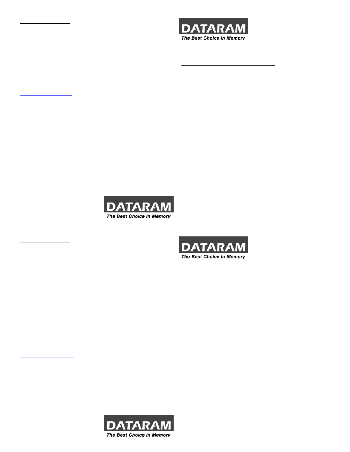
3. If you need to remove existing memory (to replace with higher density
modules for example), do that now by pressing down on the ejection
levers on both sides of module slots. Carefully pull the modules straight
out of the slots and set them down on an antistatic mat.
Caution: Confirm the modules are fully and evenly seated in the slots.
Improper seating can cause electrical shorts that can damage
the memor
and/or the system.
8. Continue to install the remaining memory modules until you have filled
the bank with four identical modules. Repeat the above steps for each
bank of memory you wish to install.
9. Reinstall the plastic cover on the CPU/Memory Card.
4. Locate the four DIMM slots in the bank you wish to populate. The system
requires bank A0 and B0 to be populated at a minimum.
5. Open both ejector levers on each slot.
10. Remove the CPU air baffle from its slot next to the CPU fan trays and
reinstall the CPU/Memory Card.
11. You must perform a reconfiguration boot in order for the O.S. to
recognize the new memory configuration.
MEMORY INSTALLATION MEMORY INSTALLATION
Note: Refer to your system owner’s manual for detailed instructions. 6. Position a module over the slot so that the alignment notches on the
Caution: System parts are sensitive to electrostatic discharge and can be
damaged by the static charge you may carry. You should wear a
rounded wrist strap, if you have one.
DIMM match the notches on the connector.
7. Press firmly on both top ends of the module, applying equal pressure
until the module snaps into place. Lock the module in the socket by
pushing up on the ejector levers until they are in their upright position.
1. Remove the CPU/Memory Card from the system and place it on an
antistatic, flat surface. If you are not immediately replacing the
CPU/Memory Card, install a CPU air baffle into its slot next to the CPU
fan trays.
2. Remove the plastic cover on the CPU/Memory Card.
3. If you need to remove existing memory (to replace with higher density
modules for example), do that now by pressing down on the ejection
levers on both sides of module slots. Carefully pull the modules straight
out of the slots and set them down on an antistatic mat.
Caution: Confirm the modules are fully and evenly seated in the slots.
Improper seating can cause electrical shorts that can damage
the memor
and/or the system.
8. Continue to install the remaining memory modules until you have filled
the bank with four identical modules. Repeat the above steps for each
bank of memory you wish to install.
9. Reinstall the plastic cover on the CPU/Memory Card.
4. Locate the four DIMM slots in the bank you wish to populate. The system
requires bank A0 and B0 to be populated at a minimum.
5. Open both ejector levers on each slot.
10. Remove the CPU air baffle from its slot next to the CPU fan trays and
reinstall the CPU/Memory Card.
11. You must perform a reconfiguration boot in order for the O.S. to
recognize the new memory configuration.
 Loading...