

Page 1
CUSTOMER SUPPORT
Dataram's Technical Support Program goes beyond the lifetime warranty,
routine calls and questions. As memory specialists for nearly 40 years,
we want to provide the most comprehensive level of service and support
in the industry.
Our Customer Support representatives can answer your questions and
give you information on system/memory configurations, upgrade options,
product specifications, compatibility and other technical topics or issues.
In Europe:
+45 70 212 217 (Phone)
+45 70 212 211 (FAX)
eusupport@dataram.com (E-mail)
In the U.S.A. and all other countries:
800-599-0071 (Toll Free)
609-799-0071 (Phone)
609-936-1369 (FAX)
usasupport@dataram.com (E-mail)
If a Dataram memory board does not function properly we will issue a
Return Material Authorization number (RMA#) for the return of the
defective module(s) and express ship a repair or replacement to you at
no charge.
P/N 06689 B
DRL2850 INSTALLATION INSTRUCTIONS FOR DELL
POWEREDGE SC1420/1425, 1800/1850/1855, 2800/2850 SERVERS
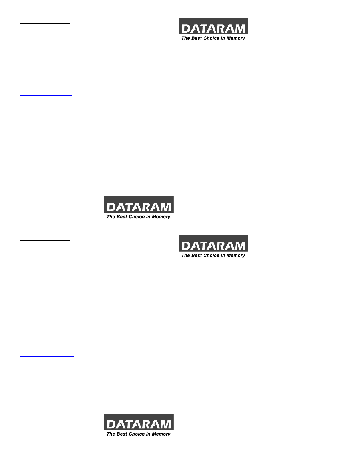
SYSTEM AND MEMORY OVERVIEW
Note: Refer to your system owner’s manual for detailed instructions and be
sure to follow all static and safety precautions.
• The PowerEdge servers will support up to 12 to 16GB of high-speed
Dual Channel DDR2 400MHz ECC SDRAM memory
• Except for a single DIMM in the first slot, odd numbered DIMMs are
not support--DIMMs must be installed in matched pairs
• DIMMs should be installed in the following order:
¾ Slots 1 and 2, 3 and 4, and then 5 and 6
• If using both single and dual rank DIMMs, they must be installed in
the following order:
¾ Dual rank DIMMs in slots 1 and 2
¾ Dual or single rank DIMMs in slots 3 and 4
¾ Single rank DIMMs only in slots 5 and 6
• If four dual rank DIMMs are used then slots 5 and 6 must be empty
Current O.S’s, such as Microsoft® Windows® XP, can only use a
maximum of 4GB of address space; however, the amount of memory
available to the O.S. may be significantly less than 4GB. Certain
components within the computer require address space in the 4GB
range. Any address space reserved for these components cannot be
used by computer memory.
P/N 06689 B
CUSTOMER SUPPORT
Dataram's Technical Support Program goes beyond the lifetime warranty,
routine calls and questions. As memory specialists for nearly 40 years,
we want to provide the most comprehensive level of service and support
in the industry.
Our Customer Support representatives can answer your questions and
give you information on system/memory configurations, upgrade options,
product specifications, compatibility and other technical topics or issues.
In Europe:
+45 70 212 217 (Phone)
+45 70 212 211 (FAX)
eusupport@dataram.com (E-mail)
In the U.S.A. and all other countries:
800-599-0071 (Toll Free)
609-799-0071 (Phone)
609-936-1369 (FAX)
usasupport@dataram.com (E-mail)
If a Dataram memory board does not function properly we will issue a
Return Material Authorization number (RMA#) for the return of the
defective module(s) and express ship a repair or replacement to you at
no charge.
P/N 06689 B
DRL2850 INSTALLATION INSTRUCTIONS FOR DELL
POWEREDGE SC1420/1425, 1800/1850/1855, 2800/2850 SERVERS
SYSTEM AND MEMORY OVERVIEW
Note: Refer to your system owner’s manual for detailed instructions and be
sure to follow all static and safety precautions.
• The PowerEdge servers will support up to 12 to 16GB of high-speed
Dual Channel DDR2 400MHz ECC SDRAM memory
• Except for a single DIMM in the first slot, odd numbered DIMMs are
not support--DIMMs must be installed in matched pairs
• DIMMs should be installed in the following order:
¾ Slots 1 and 2, 3 and 4, and then 5 and 6
• If using both single and dual rank DIMMs, they must be installed in
the following order:
¾ Dual rank DIMMs in slots 1 and 2
¾ Dual or single rank DIMMs in slots 3 and 4
¾ Single rank DIMMs only in slots 5 and 6
• If four dual rank DIMMs are used then slots 5 and 6 must be empty
Current O.S’s, such as Microsoft® Windows® XP, can only use a
maximum of 4GB of address space; however, the amount of memory
available to the O.S. may be significantly less than 4GB. Certain
components within the computer require address space in the 4GB
range. Any address space reserved for these components cannot be
used by computer memory.
P/N 06689 B
Page 2
MEMORY REMOVAL
g
y
g
y
Note: Refer to your system owner’s manual for detailed instructions.
Caution: System parts are sensitive to electrostatic discharge and can be
damaged by the static charge you may carry. You should wear a
rounded wrist strap.
1. Turn off the system and peripheral devices, and disconnect the power
cords and all external cables.
2. If you need to remove existing memory (to replace with higher density
modules for example), do that now by pressing down on the ejection
levers on both sides of module slots. Carefully pull the modules straight
out of the slots and set them down on an antistatic mat.
MEMORY INSTALLATION
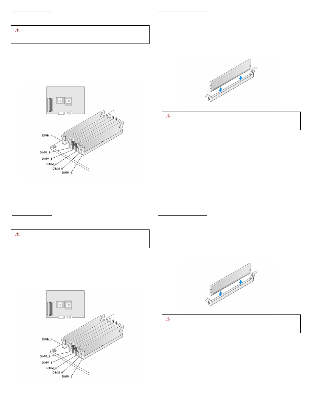
3. Open both ejector levers on each slot.
4. Position a module over the slot so that the alignment notches on the
DIMM match the notches on the connector.
5. Press firmly with your thumbs on both top ends of the module, applying
equal pressure until the module snaps into place. Lock the module in the
socket by pushing up on the ejector levers until they are in their upright
position.
Caution: Confirm the modules are fully and evenly seated in the slots.
Improper seating can cause electrical shorts that can damage
the memor
and/or the system.
6. Continue to install the remaining memory modules until you have filled
the bank with two identical modules. Repeat the above steps for each
bank of memory you wish to install.
7. Reconnect the power cords and external cables, and turn on the system.
8. After you reboot, ensure the system recognizes the new memory
configuration.
MEMORY REMOVAL MEMORY INSTALLATION
Note: Refer to your system owner’s manual for detailed instructions. 3. Open both ejector levers on each slot.
Caution: System parts are sensitive to electrostatic discharge and can be
damaged by the static charge you may carry. You should wear a
rounded wrist strap.
1. Turn off the system and peripheral devices, and disconnect the power
cords and all external cables.
4. Position a module over the slot so that the alignment notches on the
DIMM match the notches on the connector.
5. Press firmly with your thumbs on both top ends of the module, applying
equal pressure until the module snaps into place. Lock the module in the
socket by pushing up on the ejector levers until they are in their upright
position.
2. If you need to remove existing memory (to replace with higher density
modules for example), do that now by pressing down on the ejection
levers on both sides of module slots. Carefully pull the modules straight
out of the slots and set them down on an antistatic mat.
Improper seating can cause electrical shorts that can damage
the memor
and/or the system.
Caution: Confirm the modules are fully and evenly seated in the slots.
6. Continue to install the remaining memory modules until you have filled
the bank with two identical modules. Repeat the above steps for each
bank of memory you wish to install.
7. Reconnect the power cords and external cables, and turn on the system.
8. After you reboot, ensure the system recognizes the new memory
configuration.
 Loading...