

Page 1
CUSTOMER SUPPORT
Dataram's Technical Support Program goes beyond the lifetime warranty,
routine calls and questions. As memory specialists since 1967, we want
to provide the most comprehensive level of service and support in the
industry.
Our Customer Support representatives can answer your questions and
give you information on system/memory configurations, upgrade options,
product specifications, compatibility and other technical topics or issues.
In Europe:
+45 70 212 217 (Phone)
+45 70 212 211 (FAX)
eusupport@dataram.com (E-mail)
In the U.S.A. and all other countries:
800-599-0071 (Toll Free)
609-799-0071 (Phone)
609-936-1369 (FAX)
usasupport@dataram.com (E-mail)
If a Dataram memory board does not function properly we will issue a
Return Material Authorization number (RMA#) for the return of the
defective module(s) and express ship a repair or replacement to you at
no charge.
P/N 06635 C
DRI630 and DRI570 MEMORY
INSTALLATION INSTRUCTIONS
SYSTEM AND MEMORY OVERVIEW
Note: Refer to your system owner’s manual for detailed instructions and be
sure to follow all static and safety precautions.
• The DRI630 and DRI570 memory upgrades are available in various
capacities for a number of IBM systems:
• Each DRI630 and DRI570 upgrade consists of four identical DIMMs.
• The pSeries 630 memory slots are located on 1 or 2 Processor
Cards, each containing 8 DIMM slots (2 banks of 4) and 1 or 2
processors. For 4-way configurations, memory should be balanced
across both Processor Cards for best performance.
• The pSeries 650 memory slots are located on 1 to 4 Processor
Cards, each containing 8 DIMM slots (2 banks of 4) and 1 or 2
processors. Each Processor Card must have an equal amount of
memory installed.
• The p5 9117-570 memory slots are located on 2 to 8 Processor
Cards, each containing 8 DIMM slots (2 banks of 4) and 1 or 2
processors.
• The p5 9118-575 has 64 DIMM slots located on the backplane.
P/N 06635 C
Page 2
MEMORY REMOVAL
g
y
g
y
Note: Refer to your system owner’s manual for detailed instructions.
Caution: System parts are sensitive to electrostatic discharge and can be
damaged by the static charge you may carry. You should wear a
rounded wrist strap.
MEMORY INSTALLATION
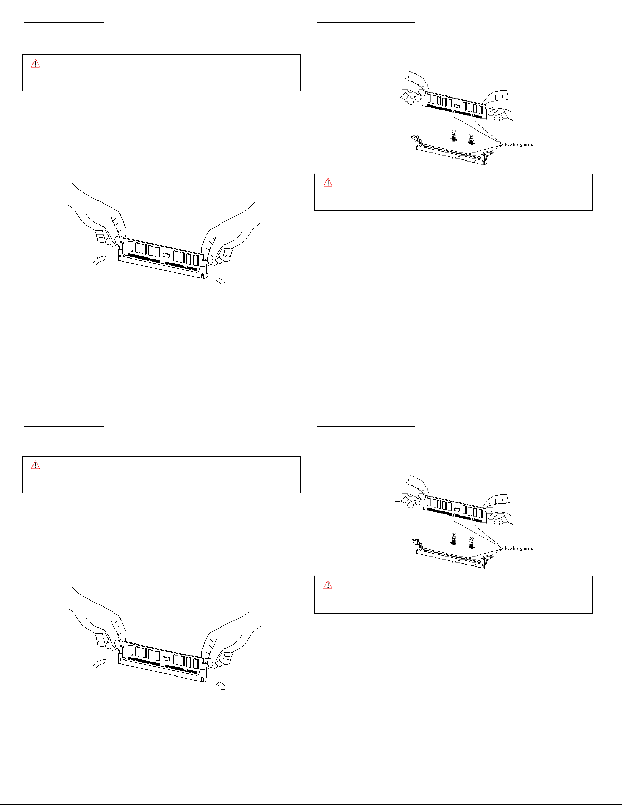
6. Press firmly on both top ends of the module, applying equal pressure
until the module snaps into place. Lock the module in the socket by
pushing up on the ejector levers until they are in their upright position.
1. Shut down the system. Remove panels, doors, cables, etc. per your
owner’s manual to gain access to the memory slots on the memory
controller.
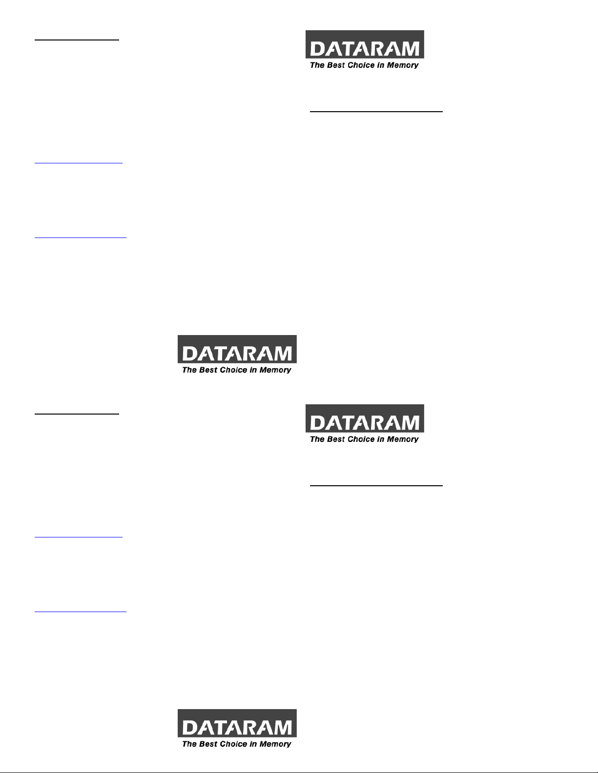
2. If you need to remove existing memory (to replace with higher density
modules for example), do that now by pressing down on the ejection
levers on both sides of module slots. Carefully pull the modules straight
out of the slots and set them down on an antistatic mat.
Caution: Confirm the modules are fully and evenly seated in the slots.
Improper seating can cause electrical shorts that can damage
the memor
and/or the system.
7. Continue to install the remaining memory modules until you have filled
the bank with four identical modules. Repeat the above steps for each
bank of memory you wish to install.
8. Reinstall the cables, panels, etc., power up the system and reboot.
3. Locate the four DIMM slots in the bank you wish to populate. The system
requires bank 0 to be populated at a minimum.
4. Open both ejector levers on each slot.
5. Position a module over the slot so that the alignment notches on the
9. Ensure the system recognizes the new memory configuration.
DIMM match the notches on the connector.
MEMORY REMOVAL MEMORY INSTALLATION
Note: Refer to your system owner’s manual for detailed instructions. 6. Press firmly on both top ends of the module, applying equal pressure
Caution: System parts are sensitive to electrostatic discharge and can be
damaged by the static charge you may carry. You should wear a
rounded wrist strap.
until the module snaps into place. Lock the module in the socket by
pushing up on the ejector levers until they are in their upright position.
1. Shut down the system. Remove panels, doors, cables, etc. per your
owner’s manual to gain access to the memory slots on the memory
controller.
2. If you need to remove existing memory (to replace with higher density
modules for example), do that now by pressing down on the ejection
levers on both sides of module slots. Carefully pull the modules straight
out of the slots and set them down on an antistatic mat.
Caution: Confirm the modules are fully and evenly seated in the slots.
Improper seating can cause electrical shorts that can damage
the memor
and/or the system.
7. Continue to install the remaining memory modules until you have filled
the bank with four identical modules. Repeat the above steps for each
bank of memory you wish to install.
8. Reinstall the cables, panels, etc., power up the system and reboot.
3. Locate the four DIMM slots in the bank you wish to populate. The system
requires bank 0 to be populated at a minimum.
4. Open both ejector levers on each slot.
5. Position a module over the slot so that the alignment notches on the
9. Ensure the system recognizes the new memory configuration.
DIMM match the notches on the connector.
 Loading...