

Dataradio T-96SR Installation Manual

Synthesized T-96SR
Hi-Spec Integrated
Wireless Modem
S e r v i c e M a n u a l
Synthesized T-96SR
Hi Spec Wireless Modem
Installation Manual
January 2004
001-4006-101 Revision 9
© 1999 by Dataradio COR Ltd.

About Dataradio
Dataradio is the leading designer and manufacturer of trusted wireless products and systems for
critical infrastructure applications. Our products have been found at the heart of mobile and
SCADA data networks around the world for over 20 years. Dataradio products include mobile
data products and systems, telemetry devices, integrated wireless modems for fixed point-topoint and point to multi-point applications and OEM solutions. Our product line is one of the
broadest and most trusted in the industry.
Product Warranty
The manufacturer's warranty statement for this product is avail ab le in our manual s or by
contacting COR Ltd. 299 Johnson Avenue, P.O. Box 1733, Waseca, MN 56093-0833. Phone
(507) 833-8819.
www.dataradio.com
Dataradio provides product brochures, case studies software downloads and product information
on our website.
Every effort is taken to provide accurate, timely product information in this technical manual. Product
updates may result in differences between the information provided herein and the product shipped. The
information in this document is subject to change without notice.
Dataradio is a registered trademark of Dataradio, Inc.

TABLE OF CONTENTS
1 GENERAL INFORMATION
1.1 INTRODUCTION. . . . . . . . . . . . . . . . . . . . . . . . . . . . . . . . . . . . . . . . . . . . . . . . . . . . . . . . . . . . . . . . . . . 1-1
GENERAL. . . . . . . . . . . . . . . . . . . . . . . . . . . . . . . . . . . . . . . . . . . . . . . . . . . . . . . . . . . . . . . . . . . . . . . . 1-1
1.2 FEATURES. . . . . . . . . . . . . . . . . . . . . . . . . . . . . . . . . . . . . . . . . . . . . . . . . . . . . . . . . . . . . . . . . . . . . . . 1-1
1.3 PART NUMBER BREAKDOWN . . . . . . . . . . . . . . . . . . . . . . . . . . . . . . . . . . . . . . . . . . . . . . . . . . . . . . 1-1
1.4 ACCESSORIES . . . . . . . . . . . . . . . . . . . . . . . . . . . . . . . . . . . . . . . . . . . . . . . . . . . . . . . . . . . . . . . . . . . 1-2
FACTORY MUTUAL NI KIT . . . . . . . . . . . . . . . . . . . . . . . . . . . . . . . . . . . . . . . . . . . . . . . . . . . . . . . . . . 1-2
T-96SR CE . . . . . . . . . . . . . . . . . . . . . . . . . . . . . . . . . . . . . . . . . . . . . . . . . . . . . . . . . . . . . . . . . . . . . . . 1-4
CSA APPROVAL . . . . . . . . . . . . . . . . . . . . . . . . . . . . . . . . . . . . . . . . . . . . . . . . . . . . . . . . . . . . . . . . . . 1-5
1.5 TRANSCEIVER IDENTIFICATION. . . . . . . . . . . . . . . . . . . . . . . . . . . . . . . . . . . . . . . . . . . . . . . . . . . . . 1-5
1.6 PRODUCT WARRANTY . . . . . . . . . . . . . . . . . . . . . . . . . . . . . . . . . . . . . . . . . . . . . . . . . . . . . . . . . . . . 1-5
1.7 FACTORY TECHNICAL SERVICE . . . . . . . . . . . . . . . . . . . . . . . . . . . . . . . . . . . . . . . . . . . . . . . . . . . . 1-5
1.8 REPLACEMENT PARTS . . . . . . . . . . . . . . . . . . . . . . . . . . . . . . . . . . . . . . . . . . . . . . . . . . . . . . . . . . . . 1-6
1.9 IF A PROBLEM ARISES.... . . . . . . . . . . . . . . . . . . . . . . . . . . . . . . . . . . . . . . . . . . . . . . . . . . . . . . . . . . 1-6
FACTORY REPAIR. . . . . . . . . . . . . . . . . . . . . . . . . . . . . . . . . . . . . . . . . . . . . . . . . . . . . . . . . . . . . . . . . 1-6
1.10 EQUIPMENT DESCRIPTION . . . . . . . . . . . . . . . . . . . . . . . . . . . . . . . . . . . . . . . . . . . . . . . . . . . . . . . . . 1-6
PHYSICAL DESCRIPTION. . . . . . . . . . . . . . . . . . . . . . . . . . . . . . . . . . . . . . . . . . . . . . . . . . . . . . . . . . . 1-6
1.11 CONFIGURATION . . . . . . . . . . . . . . . . . . . . . . . . . . . . . . . . . . . . . . . . . . . . . . . . . . . . . . . . . . . . . . . . . 1-7
T-96SR FIELD PROGRAMMING SOFTWARE . . . . . . . . . . . . . . . . . . . . . . . . . . . . . . . . . . . . . . . . . . . 1-7
DIAGNOSTICS AND REMOTE COMMANDS . . . . . . . . . . . . . . . . . . . . . . . . . . . . . . . . . . . . . . . . . . . . 1-7
ADDRESSING . . . . . . . . . . . . . . . . . . . . . . . . . . . . . . . . . . . . . . . . . . . . . . . . . . . . . . . . . . . . . . . . . . . . 1-7
ONLINE DIAGNOSTICS. . . . . . . . . . . . . . . . . . . . . . . . . . . . . . . . . . . . . . . . . . . . . . . . . . . . . . . . . . . . . 1-8
OFFLINE DIAGNOSTICS . . . . . . . . . . . . . . . . . . . . . . . . . . . . . . . . . . . . . . . . . . . . . . . . . . . . . . . . . . . . 1-8
REMOTE COMMANDS . . . . . . . . . . . . . . . . . . . . . . . . . . . . . . . . . . . . . . . . . . . . . . . . . . . . . . . . . . . . . 1-8
1.12 NETWORK CONFIGURATION . . . . . . . . . . . . . . . . . . . . . . . . . . . . . . . . . . . . . . . . . . . . . . . . . . . . . . . 1-9
GENERAL. . . . . . . . . . . . . . . . . . . . . . . . . . . . . . . . . . . . . . . . . . . . . . . . . . . . . . . . . . . . . . . . . . . . . . . . 1-9
BASIC NETWORK . . . . . . . . . . . . . . . . . . . . . . . . . . . . . . . . . . . . . . . . . . . . . . . . . . . . . . . . . . . . . . . . . 1-9
NETWORK USING T-BASE . . . . . . . . . . . . . . . . . . . . . . . . . . . . . . . . . . . . . . . . . . . . . . . . . . . . . . . . . 1-10
NETWORK USING T-BASE REPEATER. . . . . . . . . . . . . . . . . . . . . . . . . . . . . . . . . . . . . . . . . . . . . . . 1-10
NETWORK USING T-96SR FOR ONLINE DIAGNOSTICS . . . . . . . . . . . . . . . . . . . . . . . . . . . . . . . . . 1-11
GENERAL SPECIFICATIONS . . . . . . . . . . . . . . . . . . . . . . . . . . . . . . . . . . . . . . . . . . . . . . . . . . . . . . . 1-12
2 OPERATION AND CONNECTION
2.1 INTRODUCTION. . . . . . . . . . . . . . . . . . . . . . . . . . . . . . . . . . . . . . . . . . . . . . . . . . . . . . . . . . . . . . . . . . . 2-1
GENERAL. . . . . . . . . . . . . . . . . . . . . . . . . . . . . . . . . . . . . . . . . . . . . . . . . . . . . . . . . . . . . . . . . . . . . . . . 2-1
2.2 FRONT PANEL. . . . . . . . . . . . . . . . . . . . . . . . . . . . . . . . . . . . . . . . . . . . . . . . . . . . . . . . . . . . . . . . . . . . 2-1
INTRODUCTION. . . . . . . . . . . . . . . . . . . . . . . . . . . . . . . . . . . . . . . . . . . . . . . . . . . . . . . . . . . . . . . . . . . 2-1
LED INDICATORS . . . . . . . . . . . . . . . . . . . . . . . . . . . . . . . . . . . . . . . . . . . . . . . . . . . . . . . . . . . . . . . . . 2-1
2.3 DTE PORT INTERFACE . . . . . . . . . . . . . . . . . . . . . . . . . . . . . . . . . . . . . . . . . . . . . . . . . . . . . . . . . . . . 2-2
RS-232 INTERFACE SIGNAL LEVELS . . . . . . . . . . . . . . . . . . . . . . . . . . . . . . . . . . . . . . . . . . . . . . . . . 2-2
INTERFACE PORT. . . . . . . . . . . . . . . . . . . . . . . . . . . . . . . . . . . . . . . . . . . . . . . . . . . . . . . . . . . . . . . . . 2-3
INTERFACE SIGNAL DESCRIPTION . . . . . . . . . . . . . . . . . . . . . . . . . . . . . . . . . . . . . . . . . . . . . . . . . . 2-4
2.4 CHANNEL SELECTION. . . . . . . . . . . . . . . . . . . . . . . . . . . . . . . . . . . . . . . . . . . . . . . . . . . . . . . . . . . . . 2-5
2.5 T-96SR FIELD PROGRAMMING SOFTWARE . . . . . . . . . . . . . . . . . . . . . . . . . . . . . . . . . . . . . . . . . . . 2-6
INTRODUCTION. . . . . . . . . . . . . . . . . . . . . . . . . . . . . . . . . . . . . . . . . . . . . . . . . . . . . . . . . . . . . . . . . . . 2-6
COM PORT SETTINGS . . . . . . . . . . . . . . . . . . . . . . . . . . . . . . . . . . . . . . . . . . . . . . . . . . . . . . . . . . . . . 2-6
COM PORT PARAMETERS. . . . . . . . . . . . . . . . . . . . . . . . . . . . . . . . . . . . . . . . . . . . . . . . . . . . . . . . . . 2-7
PRIMARY AND SECONDARY PORT SETTINGS COMMUNICATIONS MODES. . . . . . . . . . . . . . . . . 2-8
PORT STATISTICS . . . . . . . . . . . . . . . . . . . . . . . . . . . . . . . . . . . . . . . . . . . . . . . . . . . . . . . . . . . . . . . . 2-9
SETUP MODEM/RADIO PARAMETERS . . . . . . . . . . . . . . . . . . . . . . . . . . . . . . . . . . . . . . . . . . . . . . . 2-10
i
Part No. 001-4006-101

MODEM OPERATING PARAMETERS . . . . . . . . . . . . . . . . . . . . . . . . . . . . . . . . . . . . . . . . . . . . . . . . .2-10
DATA TYPE . . . . . . . . . . . . . . . . . . . . . . . . . . . . . . . . . . . . . . . . . . . . . . . . . . . . . . . . . . . . . . . . . . . . . .2-14
NETWORK TYPE. . . . . . . . . . . . . . . . . . . . . . . . . . . . . . . . . . . . . . . . . . . . . . . . . . . . . . . . . . . . . . . . . .2-14
RADIO SETUP PARAMETERS . . . . . . . . . . . . . . . . . . . . . . . . . . . . . . . . . . . . . . . . . . . . . . . . . . . . . . .2-15
SETUP RADIO/MODEM FREQUENCIES . . . . . . . . . . . . . . . . . . . . . . . . . . . . . . . . . . . . . . . . . . . . . . .2-17
VERSION REQUEST. . . . . . . . . . . . . . . . . . . . . . . . . . . . . . . . . . . . . . . . . . . . . . . . . . . . . . . . . . . . . . .2-18
WRITING/READING T-96SR PARAMETERS . . . . . . . . . . . . . . . . . . . . . . . . . . . . . . . . . . . . . . . . . . . .2-18
CLONE PROGRAMMABLE PARAMETERS . . . . . . . . . . . . . . . . . . . . . . . . . . . . . . . . . . . . . . . . . . . . .2-19
DIAGNOSTIC IDS AND ALARMS . . . . . . . . . . . . . . . . . . . . . . . . . . . . . . . . . . . . . . . . . . . . . . . . . . . . .2-19
OFFLINE LINK TEST. . . . . . . . . . . . . . . . . . . . . . . . . . . . . . . . . . . . . . . . . . . . . . . . . . . . . . . . . . . . . . .2-21
OFFLINE DIAGNOSTICS . . . . . . . . . . . . . . . . . . . . . . . . . . . . . . . . . . . . . . . . . . . . . . . . . . . . . . . . . . .2-22
ONLINE DIAGNOSTICS . . . . . . . . . . . . . . . . . . . . . . . . . . . . . . . . . . . . . . . . . . . . . . . . . . . . . . . . . . . .2-26
USER TEST. . . . . . . . . . . . . . . . . . . . . . . . . . . . . . . . . . . . . . . . . . . . . . . . . . . . . . . . . . . . . . . . . . . . . .2-28
PACKET TEST. . . . . . . . . . . . . . . . . . . . . . . . . . . . . . . . . . . . . . . . . . . . . . . . . . . . . . . . . . . . . . . . . . . .2-29
ARRAY TEST. . . . . . . . . . . . . . . . . . . . . . . . . . . . . . . . . . . . . . . . . . . . . . . . . . . . . . . . . . . . . . . . . . . . .2-32
ASCII/HEX TERMINAL . . . . . . . . . . . . . . . . . . . . . . . . . . . . . . . . . . . . . . . . . . . . . . . . . . . . . . . . . . . . .2-34
ASCII TERMINAL. . . . . . . . . . . . . . . . . . . . . . . . . . . . . . . . . . . . . . . . . . . . . . . . . . . . . . . . . . . . . . . . . .2-34
HEX TERMINAL. . . . . . . . . . . . . . . . . . . . . . . . . . . . . . . . . . . . . . . . . . . . . . . . . . . . . . . . . . . . . . . . . . .2-35
PROGRAM CODE . . . . . . . . . . . . . . . . . . . . . . . . . . . . . . . . . . . . . . . . . . . . . . . . . . . . . . . . . . . . . . . . .2-35
END TO END TEST. . . . . . . . . . . . . . . . . . . . . . . . . . . . . . . . . . . . . . . . . . . . . . . . . . . . . . . . . . . . . . . .2-35
2.6 T-96SR HELP FILES . . . . . . . . . . . . . . . . . . . . . . . . . . . . . . . . . . . . . . . . . . . . . . . . . . . . . . . . . . . . . . .2-38
2.7 OPTIMIZING YOUR SYSTEM . . . . . . . . . . . . . . . . . . . . . . . . . . . . . . . . . . . . . . . . . . . . . . . . . . . . . . . .2-38
3 GLOSSARY
DEFINITIONS. . . . . . . . . . . . . . . . . . . . . . . . . . . . . . . . . . . . . . . . . . . . . . . . . . . . . . . . . . . . . . . . . . . . . .3-1
APPENDIX
T-96SR VHF CERTIFICATE OF CONFORMITY. . . . . . . . . . . . . . . . . . . . . . . . . . . . . . . . . . . . . . . . . . A-1
T-96SR UHF CERTIFICATE OF CONFORMITY. . . . . . . . . . . . . . . . . . . . . . . . . . . . . . . . . . . . . . . . . . A-2
T-96SR VHF DECLARATION OF CONFORMITY. . . . . . . . . . . . . . . . . . . . . . . . . . . . . . . . . . . . . . . . . A-3
T-96SR UHF DECLARATION OF CONFORMITY. . . . . . . . . . . . . . . . . . . . . . . . . . . . . . . . . . . . . . . . . A-4
DECLARATION OF PRODUCT QUALITY ASSURANCE . . . . . . . . . . . . . . . . . . . . . . . . . . . . . . . . . . . A-5
LIST OF TABLES
1-1 T-96SR PART NUMBER BREAKDOWN. . . . . . . . . . . . . . . . . . . . . . . . . . . . . . . . . . . . . . . . . . . . . . . . .1-1
1-2 ACCESSORIES . . . . . . . . . . . . . . . . . . . . . . . . . . . . . . . . . . . . . . . . . . . . . . . . . . . . . . . . . . . . . . . . . . . .1-2
1-3 DIAGNOSTICS AND COMMANDS . . . . . . . . . . . . . . . . . . . . . . . . . . . . . . . . . . . . . . . . . . . . . . . . . . . . .1-7
1-4 T-96SR ADDRESSES . . . . . . . . . . . . . . . . . . . . . . . . . . . . . . . . . . . . . . . . . . . . . . . . . . . . . . . . . . . . . . .1-7
2-1 LED INDICATORS. . . . . . . . . . . . . . . . . . . . . . . . . . . . . . . . . . . . . . . . . . . . . . . . . . . . . . . . . . . . . . . . . .2-1
2-2 RS-232 SIGNAL LEVELS . . . . . . . . . . . . . . . . . . . . . . . . . . . . . . . . . . . . . . . . . . . . . . . . . . . . . . . . . . . .2-2
2-3 DATA PORT CONNECTOR PINOUT . . . . . . . . . . . . . . . . . . . . . . . . . . . . . . . . . . . . . . . . . . . . . . . . . . .2-2
2-4 SIGNAL DESCRIPTION. . . . . . . . . . . . . . . . . . . . . . . . . . . . . . . . . . . . . . . . . . . . . . . . . . . . . . . . . . . . . .2-4
2-5 CHANNEL SELECTION. . . . . . . . . . . . . . . . . . . . . . . . . . . . . . . . . . . . . . . . . . . . . . . . . . . . . . . . . . . . . .2-5
2-6 COMMUNICATION MODES . . . . . . . . . . . . . . . . . . . . . . . . . . . . . . . . . . . . . . . . . . . . . . . . . . . . . . . . . .2-8
2-7 RS-232 INTERFACE AND NETWORK BAUD RATES . . . . . . . . . . . . . . . . . . . . . . . . . . . . . . . . . . . . .2-13
Part No. 001-4006-101
ii

2-8 RTS/CTS DELAYS. . . . . . . . . . . . . . . . . . . . . . . . . . . . . . . . . . . . . . . . . . . . . . . . . . . . . . . . . . . . . . . . .2-13
2-9 SUPPORTED USER FORMATS AND MODEM PROGRAMMING. . . . . . . . . . . . . . . . . . . . . . . . . . . .2-13
2-10 Y-CABLE CONNECTIONS . . . . . . . . . . . . . . . . . . . . . . . . . . . . . . . . . . . . . . . . . . . . . . . . . . . . . . . . . .2-31
2-11 SWR/REV POWER INTERPRETATION . . . . . . . . . . . . . . . . . . . . . . . . . . . . . . . . . . . . . . . . . . . . . . . .2-40
LIST OF FIGURES
1-1 FM APPROVED EXTERNAL CONNECTIONS . . . . . . . . . . . . . . . . . . . . . . . . . . . . . . . . . . . . . . . . . . . .1-2
1-2 INSTALLATION MOUNTING DIMENSIONS . . . . . . . . . . . . . . . . . . . . . . . . . . . . . . . . . . . . . . . . . . . . . .1-3
1-3 TRANSCEIVER IDENTIFICATION . . . . . . . . . . . . . . . . . . . . . . . . . . . . . . . . . . . . . . . . . . . . . . . . . . . . .1-5
1-4 BASIC NETWORK. . . . . . . . . . . . . . . . . . . . . . . . . . . . . . . . . . . . . . . . . . . . . . . . . . . . . . . . . . . . . . . . . .1-9
1-5 NETWORK USING T-BASE. . . . . . . . . . . . . . . . . . . . . . . . . . . . . . . . . . . . . . . . . . . . . . . . . . . . . . . . . .1-10
1-5 NETWORK USING T-BASE REPEATER . . . . . . . . . . . . . . . . . . . . . . . . . . . . . . . . . . . . . . . . . . . . . . .1-10
1-6 NETWORK WITH MONITORING T-96SR. . . . . . . . . . . . . . . . . . . . . . . . . . . . . . . . . . . . . . . . . . . . . . .1-11
2-1 T-96SR FRONT PANEL. . . . . . . . . . . . . . . . . . . . . . . . . . . . . . . . . . . . . . . . . . . . . . . . . . . . . . . . . . . . . .2-1
2-2 DE-15F CONNECTOR DIAGRAM. . . . . . . . . . . . . . . . . . . . . . . . . . . . . . . . . . . . . . . . . . . . . . . . . . . . . .2-2
2-3 CABLE PINOUT. . . . . . . . . . . . . . . . . . . . . . . . . . . . . . . . . . . . . . . . . . . . . . . . . . . . . . . . . . . . . . . . . . . .2-3
2-4 DE-15 TO DB-9 TERMINATED CABLE ASSEMBLY ACCESSORY. . . . . . . . . . . . . . . . . . . . . . . . . . . .2-4
2-5 FIELD PROGRAMMING SOFTWARE STARTUP SCREEN. . . . . . . . . . . . . . . . . . . . . . . . . . . . . . . . . .2-6
2-6 PORT SETTINGS SCREEN . . . . . . . . . . . . . . . . . . . . . . . . . . . . . . . . . . . . . . . . . . . . . . . . . . . . . . . . . .2-7
2-7 PORT STATISTICS SCREEN . . . . . . . . . . . . . . . . . . . . . . . . . . . . . . . . . . . . . . . . . . . . . . . . . . . . . . . . .2-9
2-8 SETUP MODEM/RADIO SCREEN . . . . . . . . . . . . . . . . . . . . . . . . . . . . . . . . . . . . . . . . . . . . . . . . . . . .2-10
2-9 NETWORK TYPE CONNECTED TO A T-96SR MODEM . . . . . . . . . . . . . . . . . . . . . . . . . . . . . . . . . . .2-14
2-10 NETWORK TYPE CONNECTED TO A T-96S/DL3276. . . . . . . . . . . . . . . . . . . . . . . . . . . . . . . . . . . . .2-14
2-11 RADIO SETUP PARAMETERS SCREEN. . . . . . . . . . . . . . . . . . . . . . . . . . . . . . . . . . . . . . . . . . . . . . .2-15
2-12 SETUP RADIO/MODEM FREQUENCIES PARAMETERS . . . . . . . . . . . . . . . . . . . . . . . . . . . . . . . . . .2-17
2-13 VERSION REQUEST SCREEN. . . . . . . . . . . . . . . . . . . . . . . . . . . . . . . . . . . . . . . . . . . . . . . . . . . . . . .2-18
2-14 CLONE PROGRAMMABLE PARAMETERS SCREEN . . . . . . . . . . . . . . . . . . . . . . . . . . . . . . . . . . . . .2-19
2-15 DIAGNOSTIC IDS AND ALARMS SCREEN . . . . . . . . . . . . . . . . . . . . . . . . . . . . . . . . . . . . . . . . . . . . .2-19
2-16 OFFLINE LINK TEST SCREEN. . . . . . . . . . . . . . . . . . . . . . . . . . . . . . . . . . . . . . . . . . . . . . . . . . . . . . .2-21
2-17 OFFLINE DIAGNOSTICS SCREEN . . . . . . . . . . . . . . . . . . . . . . . . . . . . . . . . . . . . . . . . . . . . . . . . . . .2-23
2-18 ONLINE DIAGNOSTICS . . . . . . . . . . . . . . . . . . . . . . . . . . . . . . . . . . . . . . . . . . . . . . . . . . . . . . . . . . . .2-26
2-19 USER TEST SCREEN. . . . . . . . . . . . . . . . . . . . . . . . . . . . . . . . . . . . . . . . . . . . . . . . . . . . . . . . . . . . . .2-28
2-20 ARRAY TEST SCREEN. . . . . . . . . . . . . . . . . . . . . . . . . . . . . . . . . . . . . . . . . . . . . . . . . . . . . . . . . . . . .2-32
2-21 ASCII TERMINAL SCREEN. . . . . . . . . . . . . . . . . . . . . . . . . . . . . . . . . . . . . . . . . . . . . . . . . . . . . . . . . .2-34
2-22 END-TO-END TEST:ASCII TERMINAL. . . . . . . . . . . . . . . . . . . . . . . . . . . . . . . . . . . . . . . . . . . . . . . . .2-36
2-23 END-TO-END TEST: TEXT MESSAGE SENT . . . . . . . . . . . . . . . . . . . . . . . . . . . . . . . . . . . . . . . . . . .2-36
2-24 TEXT MESSAGE RECEIVED . . . . . . . . . . . . . . . . . . . . . . . . . . . . . . . . . . . . . . . . . . . . . . . . . . . . . . . .2-37
2-25 HEX TERMINAL. . . . . . . . . . . . . . . . . . . . . . . . . . . . . . . . . . . . . . . . . . . . . . . . . . . . . . . . . . . . . . . . . . .2-37
2-26 T-96SR PROGRAMMING SOFTWARE HELP START SCREEN . . . . . . . . . . . . . . . . . . . . . . . . . . . . .2-38
Part No. 001-4006-101
iii

REVISION HISTORY
Revision 9
Removed references to internal DIP switches.
Revision 8
September 2003
Changes to General Specifications. Added CSA approval information to Section 1 and CSA certificate to Appendix
A. Added Appendix B: product warranties.
Revision 7
March 2003
Updates to manual to reflect new UHF RF board. Added End-to-End Test information to Section 2.
Revision 6
April 2002
Updates to manual to reflect RF board change, corrected screen images.
Revision 5
October 2001
Updated Table 2-7, added Signal Description Table 2-4.
Revision 4
January 2001
Added CE information to Section 1 of manual .
Revision 3
June 2000
Added FM NI kit information to Section 1 of manual.
Revision 2
March 2000
Hard copy format change to technical manual.
Revision 1
January 2000
Added DB-9 to DE-15 cable information to Section 2-4, various formatting changes.
Part No. 001-4006-101
iv
SECTION 1
GENERAL INFORMATION
1.1 INTRODUCTION
1.1.1 GENERAL
This installation manual provides information for selecting, installing, operating, and maintaining the
Dataradio T-96SR wireless modem.
1.2 FEATURES
The T -96SR is a transparent real-time wireless modem designed primarily for SCADA (Supervisory Control
and Data Acquisition) and telemetry use. Features of the T-96SR include:
z Data speeds of 4800 to 19200 b/s (9600 b/s maximum in half-channels) using a standard RS-232 int erface
z Built-in 8 channel synthesized radio transceiver for VHF and UHF bands
z Power output of 1 W to 5 W (software controlled)
z Half duplex or simplex operation
z Transmit control via RTS
z Online diagnostics monitoring
z Offline local and remote diagnostics
z Compatible with Dataradio T-Base for base station or repeater use
z Compatible with any Dataradio Interoperability Standard (DI-OS) equipment including the T -96S for data
I
NTEROPERABILITY
rates of 4800 and 9600 b/s.
®
1.3 T-96SR PART NUMBER BREAKDOWN
The following table shows the breakdown of the T-96SR part number.
Table 1-1 T-96SR Part Number Breakdown
242-40W6-XYZ(F)*
W X Y Z (UHF units) F (optional)
1 VHF 0 406-430 MHz 1 12.5 kHz 0 406-422 MHz Fan option
4 UHF 1 380-403 MHz 3 25 kHz 1 414-430 MHz
2 403-419 MHz
3 419-435 MHz
4 132-150 MHz (VHF), 435-451 MHz (UHF)
5 450-470 MHz (UHF)
6 150-174 MHz (VHF), 464-480 MHz (UHF)
7 480-496 MHz
8 496-512 MHz
1-1
001-4006-101
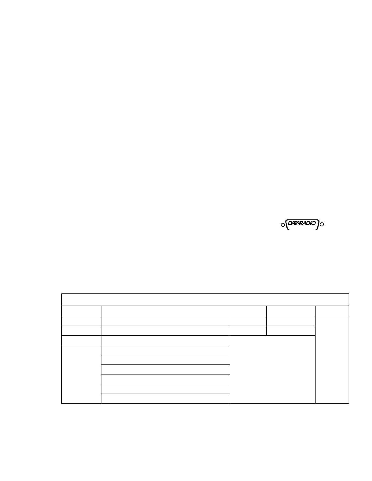
1.4 ACCESSORIES
Table 1-2 T-96SR Accessories
Accessory DRL Part Number
Unterminated Power Cable 023-3276-007
DE-15 to DB-9 Power and Data Cable 697-0000-001
Field Programming Kit 250-4006-001
Factory Mutual NI Kit 023-1000-100
Installation Manual for T - 96SR 001-4006-102 (CD ROM version)
001-4006-101 (Hard Copy version)
DIN Rail Mount 250-4800-406
Switching Power Converter 250-0300-075 (7.5 VDC VOut, 3 Amp)
250-0300-133 (13.3 VDC V Out, 3 Amp)
For information about sales and accessories, contact your sales representative. In the U.S. phone 1-800-9927774 or 1-507-833-8819.
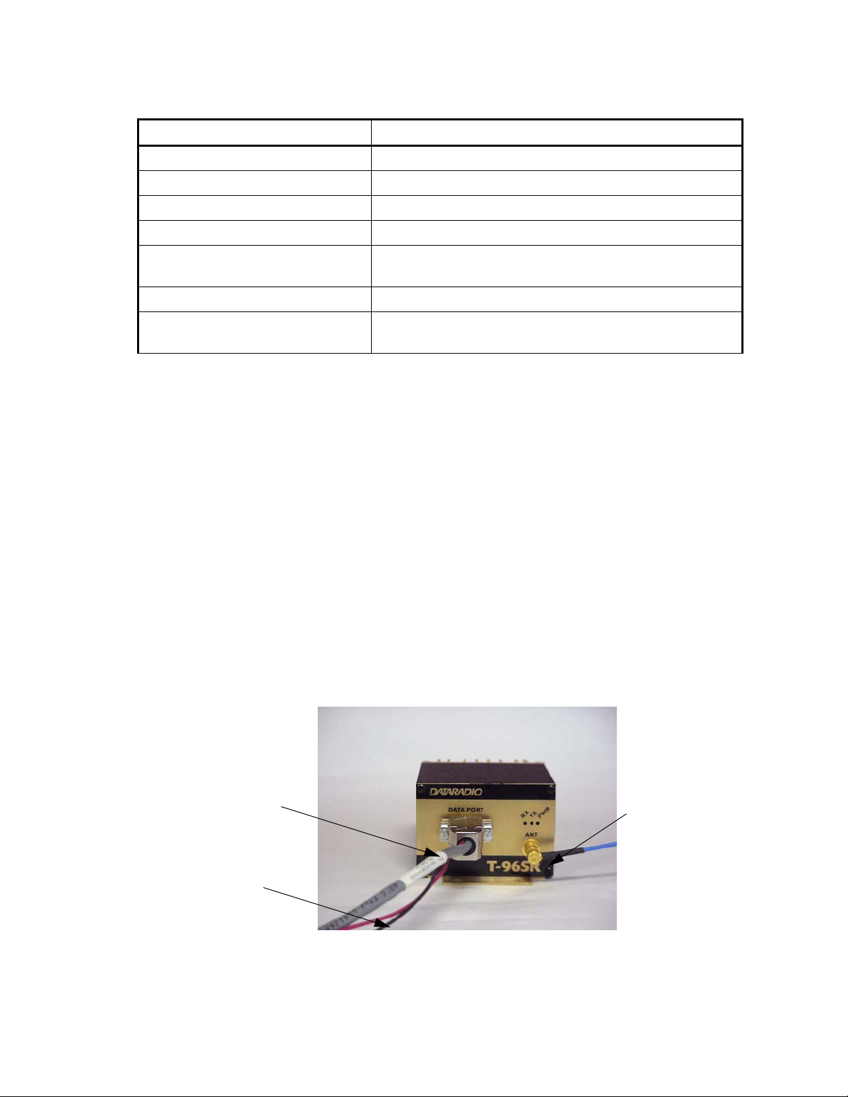
1.4.1 FACTORY MUTUAL NI KIT
The T-96SR with the Factory Mutual NI Kit (part number 023-1000-100) is approved as non-incendive for
Class 1, Groups ABCD, Division 2, hazardous locations by Factory Mutual Research Corporation. This
option includes approval for International Electrotechnical Commission (IEC) Class 1, Zone 2.
Approved models are labeled with this rating. Only units with the Factory Mutual approved label carry the
non-incendive rating. Contact your Dataradio representative for more information con cerning your
particular requirements.
Installation, service, and repair of the FM approved units must be in accordance with the instructions found
in this manual and the National Electrical Code (ANSI-NFPA70) Division 2 Hazardous (classified) Location
Incendive Wiring Techniques. Mount the unit in an enclosure or assembly. Route all interconnecting cables
(DC power and coaxial) through conduit as specified in the National Electrical Code document referenced
above. For further guidance on installation, see ANSI/ISA-RPI2.6: Installation of Intrinsically Safe Systems
for Hazardous (Classified) Locations.
User Interface Cable
DC Power (13.3V)
To Antenna System
(SMA Connector)
Figure 1-1 FM Approved External Connections
001-4006-101
1-2
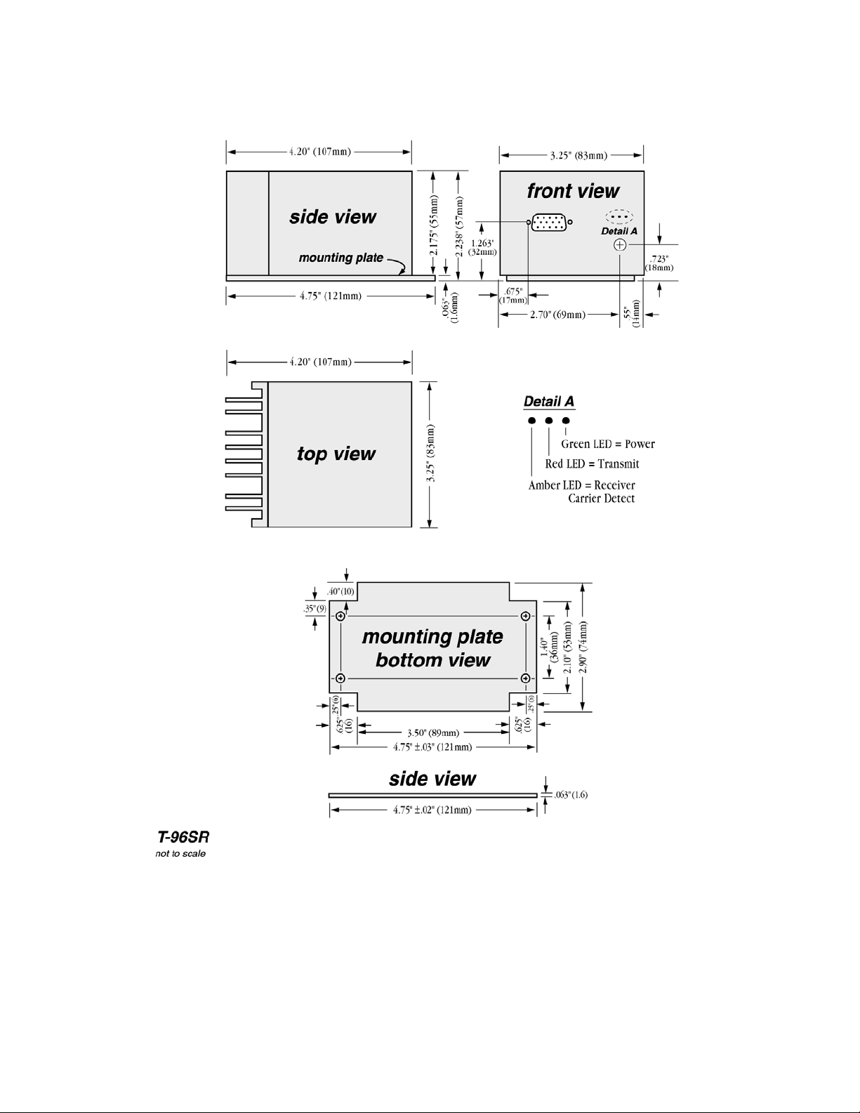
Figure 1-2 Installation Mounting Dimensions
001-4006-101
1-3

1.4.2 T-96SR CE
Important Notice/Warning on restrictive use in all EU and EFTA member states:
This device is a VHF/UHF Radio data transmitter intended for indoor and outdoor use. Operation of this device is
subject to end-user licence. The end user is strongly advised to contact the local frequency management authorities to
obtain such an end-user licence according to local legislations and frequency allocations. The manufacturer takes no
responsibility for any unauthorized use of this device.
Avis important/Avertissement au sujet de restrictions d’utilisation applicables à l’intérieur d’un pays membre de l’UE
ou de l’AELE :
Cet appareil est un émetteur radio opérant en VHF/UHF, d’usage intérieur ou extérieur, utilisé pour la transmission de
données. L ’opération de cet appareil est assujettie aux termes et conditions de la licence émise à l’utilisateur final. Il est
fortement conseillé à l’utilisateur final de contacter les autorités locales légalement responsables de la gestion et de
l’allocation des fréquences radios et d’obtenir auprès d’eux toute licence d’opération requise. Le manufacturier
n’assume aucune responsabilité pour l’usage non réglementaire de cet appareil.
Avvertenza importante per l'uso limitato ai paesi della Comunita' Europea ed EFTA. Questo dispositivo e' un trasmettitore radiofonico di dati di VHF/UHF per uso interno ed esterno. Bisogna avere una licenza per ultilizzare questo dispositivo. Consigliamo fortemente a chi usera' questo trasmettitore di contattare le autorita' locali che amministrano la
gestione delle frequenze per ottenere un'autorizzazione che sia conforme alle leggi locali, e, con questa ottenere l'assegnamento della frequenza. Il fornitore di questo dispositivo non e' responsabile per l'uso non autorizzato.
O aviso/advertir importante no uso restritivo estados de todo o membro do EU e do EFTA: Este dispositivo é um
transmissor de rádio dos dados de VHF/UHF pretendido para o uso indoor e ao ar livre. A operação deste dispositivo é
sujeita à licença do end-user. O usuário da extremidade é recomendado fortemente contatar as autoridades locais da
gerência da freqüência para obter tal licença do end-user de acordo com legislações e alocamentos locais da freqüência.
O fabricante das tomadas nenhuma responsabilidade para algum uso desautorizado deste dispositivo.
Advertencia/Noticia: Importante uso restrictivo en Estados miembros de toda la Unión Europea y de Aelc: Este
equipo es un radio transmisor de datos en las bandas de VHF y UHF previsto para uso en interiores y exteriores. La
operación de este equipo es conforme a licencia obtenida por el usuario final. Se aconseja al usurario final que entre
en contacto con las autoridades locales que aprueban el uso de frecuencias, para obtener su propia asignación de
frecuencia de acuerdo a la legislacion de cada pais. El fabricante no se hace responsable del uso de los equipos sin la
aprobación de frecuencia por las autoridades locales.
See Appendix for CE Certificates.
Wichtige Information/Warnung hinsichtlich Gebrauch in allen EU- und EFTA-Mitgliederstaaten:
Dieses Gerät ist ein VHF/UHF Dat en – Funkgerät, da ß sowoh l innen a ls auch im Freien betr i eben werden ka nn. Die
Inbet riebn ahm e d ieses Ger ä tes ist a bhängig von ein er Nut z erli zenz . Wir empfehlen dem Gerä tebetreiber si ch mi t den
zuständigen Frequenz – Regulierungsbehörden in Verbindung zu setzen, um die entsprechenden Lizenzen, gemäß gültiger
Gesetzgebung, zu beantragen. Der Hersteller dieses Daten – Funkgerätes kann keine Haftung für nicht ordnun gsgemäßen
(gesetz es k onformen) Betrieb des Gerät es ü bernehmen.
001-4006-101
1-4

1.4.3 CANADIAN STANDARDS ASSOCIATION (CSA)
The T-96SR is approved by the Canadian Standards Association. This approval is equivalent to a Factory
Mutual Class 1, Division 2, Groups A, B, C and D approval. CSA is a not-for-profit membership based
organization that serves business, industry, government and consumers in Canada and provides product
safety and other standards acceptance for process equipment used in hazardous locations.
See Appendix A for certificate.
1.5 TRANSCEIVER IDENTIFICATION
The transceiver identification number is printed on a label that is affixed to the PC board. The following
information is contained in that number:
Model
40W6 2 A
Ninth Digit
of PN
Revision
Letter
Week No.
of Year
Manufacture
Date
1 4 3
Plant
Year
Warranty
Number
A 12345
Figure 1-3 Transceiver Identification Nomenclature
1.6 PRODUCT WARRANTY
Dataradio warranties are available in Appendix B and are included in .pdf format on CD versions of
Dataradio manuals.
1.7 FACTORY TECHNICAL SERVICE
The T echnical Service Department of Dataradio COR Ltd. (DRL) provides customer assistance on technical
problems and serves as an interface with factory repair facilities. They can be reached by mail, phone, and
email at:
Dataradio COR Ltd.
Technical Service Department
299 Johnson Avenue, P.O. Box 1733
Waseca, MN 56093-0833
1-800-992-7774 or 1-507-833-8819
Fax: 507-833-6748
Email address: support@dataradio-cor.com
Technical Service hours: Monday through Friday 7:30 A.M. to 4:30 P.M. Central Time
1-5
001-4006-101

1.8 REPLACEMENT PARTS
This product is not field serviceable, except by the replacement of complete units. Specialized equipment
and training is required to repair logic boards and radio modules.
1.9 IF A PROBLEM ARISES...
Component level repair is not recommended on the T-96SR. DRL’s factory is best equipped to diagnose
problems and make component level repairs. Contact Technical Service before returning equipment. A
service technician may suggest a solution eliminating the need to return equipment.
1.9.1 FACTORY REPAIR
Dataradio products are designed for long life and failure-free operation. If a problem arises, factory service
is available. Contact the Technical Service Department before returning equipment.
A Return Material Authorization (RMA) is required when returning equipment to Dataradio for repair.
Contact the Technical Service Department at 1-800-992-7774 or 1-507-833-8819 (extension 6707) to
request an RMA number. RMA’s are available through our website at www.dataradio.com/
products_tech_adv.html. Be prepared to give the equipment model and serial number, your account number
(if known), and billing and shipping addresses.
Include the RMA number, a complete description of the problem, and the name and phone number of a
contact person with the returned units. This information is important. The technician may have questions
that need to be answered to identify the problem and repair the equipment. The RMA number helps locate
your equipment in the repair lab if there is a need to contact Dataradio concerning the equipment.
Units sent in for repair will be returned to the customer re-tuned to the current Dataradio Test and Tune
Procedure and will conform to all specifications noted in this section
Customers are responsible for shipping charges (to Dataradio) for returned units in warranty. Units in
warranty are repaired free of charge unless there is evidence of abuse or damage beyond the terms of the
warranty. Dataradio covers return shipping costs for equipment repaired while under warranty.
Units out of warranty are subject to repair service charges. Customers are responsible for shipping charges
(to and from Dataradio) on units out of warranty. Return shipping instructions are the responsibility of the
customer.
1.10 EQUIPMENT DESCRIPTION
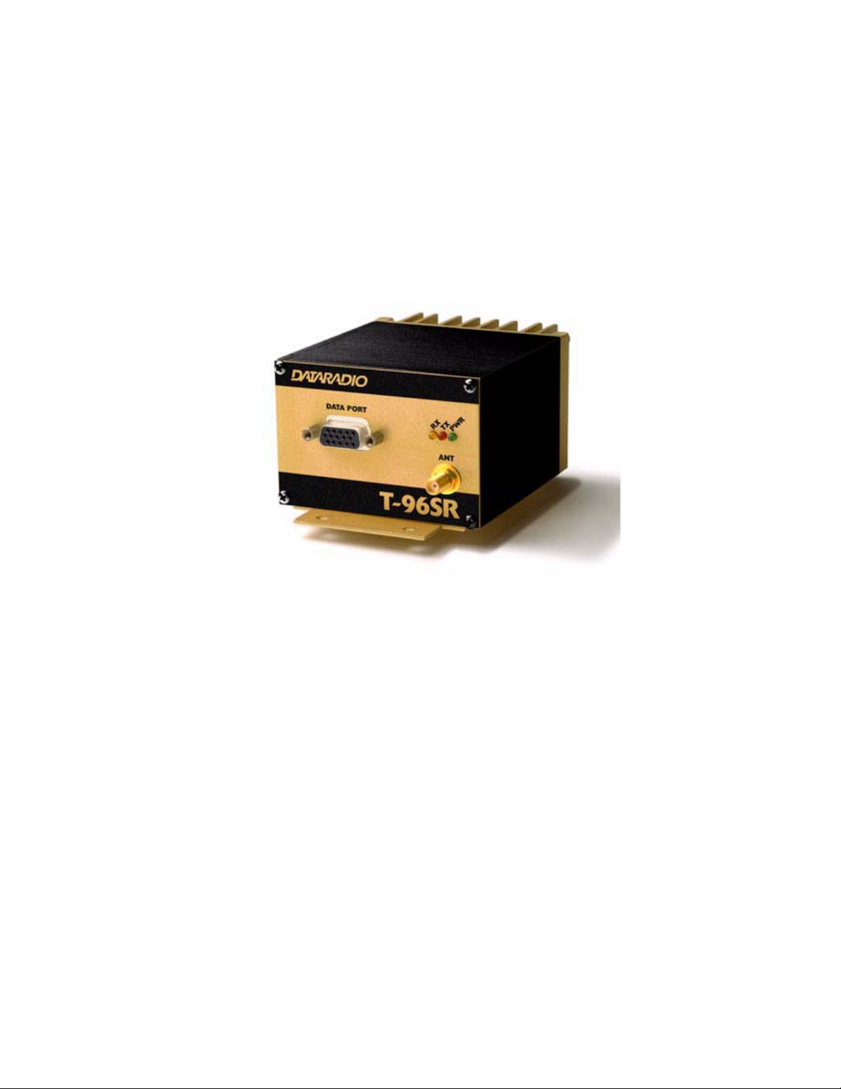
1.10.1 PHYSICAL DESCRIPTION
The T-96SR consists of a logic printed circuit board (PCB) (which includes the modem circuitry) and a
separate radio module. The two boards plug directly together and slide into the rails of an extruded
aluminum case. The front panel includes the DE-15 data connector and an SMA antenna connector, as well
as three LED indicators. Power connections are made through the DE-15 data connector. The unit is not
hermetically sealed and should be mounted in a suitable enclosure where dust and/or a corrosive atmosphere
are anticipated. There are no external switches or adjustments. Operating parameters are set using software.
001-4006-101
1-6

1.11 CONFIGURATION
1.11.1 T-96SR FIELD PROGRAMMING SOFTWARE
Operating characteristics of the T-96SR are configured by the Field Programming Software. Offline
Diagnostics and Online Diagnostics give access to Offline Diagnostics and commands (local and remote)
and online diagnostics monitoring (with or without a T-Base/R). Programming software is Windows
® based
and requires a Windows 95 or better operating system. Context sensitive help and printable help files are
provided with this program.
The T-96SR requires the use of the Field Programming Software for configuration, adjustment and
diagnostics.
1.11.2 DIAGNOSTICS AND REMOTE COMMANDS
Diagnostics and remote commands are processed using the T-96SR Offline diagnostics utility. Diagnostics
can be monitored using the T- 96SR Online Diagnostics utility.
Table 1-3 Diagnostics and Commands
Online Diagnostics Information is automatically sent by each
unit at the beginning of every transmission.
May be disabled for back compatibility with
Dataradio T-Modem 96 or Motorola RNet
9600
Offline Diagnostics Information is sent by a specific unit in
response to an inquiry by the master or
monitoring station
Remote Commands Commands may be sent by the master or
monitoring station to any specific remote unit
1.11.3 ADDRESSING
Each T-96SR has addressing capability which is used for diagnostics and remote commands only.
Table 1-4 T-96SR Addresses
ID Number This value (maximum 1023) is assigned at the factory but may be
modified using the Field Programming Software. The ID Number
is used to uniquely identify the T -96SR for remote commands and
Offline Diagnostics. The ID Number may have values within the
range of 1 to 4294967295 but multiples of 1024 should not be
used
Short ID This value (maximum 1023) is the low order 10 bits of the ID
Number. It is used to identify online diagnostics only. It may not
be modified directly using the Field Programming Software; it is
always derived from the ID Number. All units within a network
should have unique Short ID numbers to avoid ambiguity in
Online Diagnostics reports.
001-4006-101
1-7

The T-96SR Field Programming Software may be used to check the value of the Short ID. When setting up a
network, we recommend checking each unit to make sure there is no duplication of Short ID numbers.
Duplications may be resolved by changing the Short ID Number.
If ID Numbers are set within the range of 1 to 1023, the ID Number and the Short ID will always have the
same value (see Table 1-4).
1.11.4 ONLINE DIAGNOSTICS
Online Diagnostics (statistics) require the use of a network configuration such as that specified in the
“Network Using T-Base” or “Network Using T-96SR for Online Diagnostics” sections. Online diagnostics
do not interfere with normal network operation. Online diagnostics provide four types of information:
z Supply voltage
z Internal temperature
z Forward and reverse power in watts
z Received signal strength (in dBm)
Each T-96SR can accumulate this information for the last 15 stations heard. The accumulated values can be
displayed using the Offline Diagnostics utility or can be dynamically monitored using the Online
Diagnostics utility.
1.11.5 OFFLINE DIAGNOSTICS
Offline diagnostics are statistics returned in response to a specific request to a particular station. The use of
this feature requires temporary suspension of user network operation. Offline diagnostics provide
information that is displayed via the Offline Diagnostics utility. Offline Diagnostics gather and displays five
types of information:
z Supply voltage
z Analog supply voltage
z Internal temperature
z Received signal strength (in dBm)
z Forward and reverse power in watts
z Preamble good & total
z Preamble DCD
1.11.6 REMOTE COMMANDS
Remote commands that may be sent using the Offline Diagnostics utility include:
Begin test transmission (several types are available)
z Get statistics (diagnostics)
z Sample network statistics (monitoring online diagnostics)
z Get parameters (configuration) from remote unit
Remote commands are sent and responses received with the host application offline.
001-4006-101
1-8
1.12 NETWORK CONFIGURATION
1.12.1 GENERAL
The T-96SR is designed to replace wire lines in SCADA, telemetry and control applications. The RS-232
serial port allows direct connection to Programmable Logic Controllers (PLCs) or Remote Terminal Units
(RTUs). Sections 1.12.2 through 1.12.5 describe network configurations.
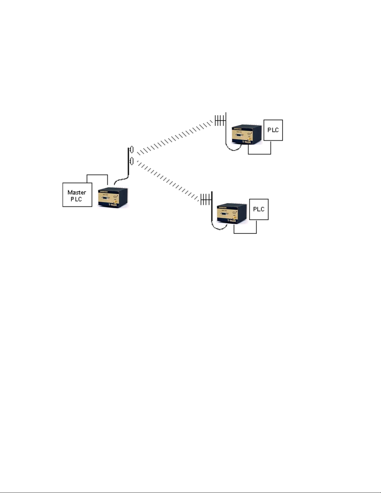
1.12.2 BASIC NETWORK
T-96SR
T-96SR
T-96SR
Figure 1-4 Basic Network
The Basic Network configuration has the following characteristics:
z Master station may be half duplex or simplex
z Online diagnostics are not available in real time
z Remote / local diagnostics and accumulated Online Diagnostics and control are available by disconnecting
the master PLC and substituting a PC running the T-96SR Field Programming Software utility.
001-4006-101
1-9
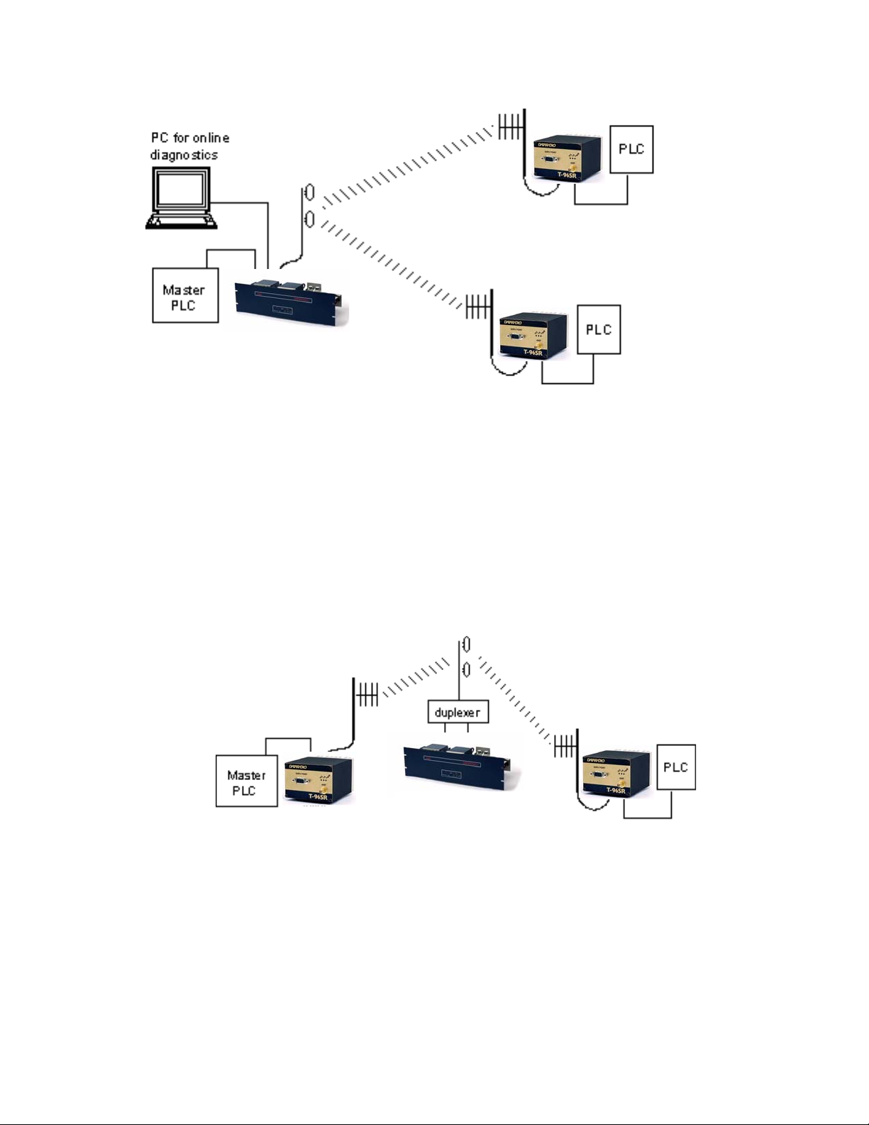
1.12.3 NETWORK USING A T-BASE
T-96SR
T-96SR
T-Base
Figure 1-5 Network Using a T-Base
The Network Using a T-Base configuration has the following characteristics:
z Master station may be full duplex (duplexer required), half duplex, or simplex
z Online diagnostics are available using the Online Diagnostics utility without disrupting network activity
z Remote / local diagnostics and statistics / control are available using the T-96SR Of fline Diagnostics utility
when connected to the Tx module (not Diag Port of T-Base)
z The T-Base provides output of Online Diagnostic information which can be processed by the T-96SR
Online Diagnostics utility or by a user-supplied network management program. Contact your sales
representative for further information.
1.12.4 NETWORK USING A T-BASE REPEATER
T-96SR
T-96SR
Figure 1-6 Network Using a T-Base Repeater
The Network Using a T-Base Repeater has the following characteristics:
z Master station and all remotes must be half duplex
z Networks described in Section 1.10.2, 1.10.3, or 1.10.5 may be used with a T-Base repeater
z The RTS/CTS delays for each T-96SR in the system must be extended as shown in Table 2-6, RTS/CTS
Delays
001-4006-101
T-Base/Repeater
1-10
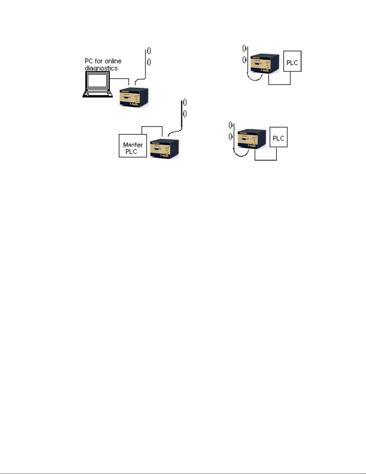
1.12.5 NETWORK USING A T-96SR FOR ONLINE DIAGNOSTICS
T-96SR
T-96SR
T-96SR
T-96SR
Figure 1-7 Network With a Monitoring T-96SR
The Network Using a T-96SR for Online Diagnostics configuration has the following characteristics:
z Master station may be half duplex or simplex
z Accumulated online diagnostics for a maximum of 15 stations are available at a monitoring site
(monitoring site must be in range of all remotes)
z Online Diagnostics are available in real time at the monitoring site
z Remote Offline Diagnostics, statistics, and control are available from the monitoring site by temporarily
disabling network activity (best if using a Master Station Antenna System)
Online Diagnostics are accumulated in the monitoring T-96SR for the last 15 sta t ions heard. This
information may be viewed using the Online Diagnostics utility. For larger networks, the T-96SR can output
raw diagnostic data only which may be interpreted for network management by the Dataradio Field
Programming Software Online Diagnostics utility or by a user-supplied software program. Contact your
sales representatives for more information.
001-4006-101
1-11

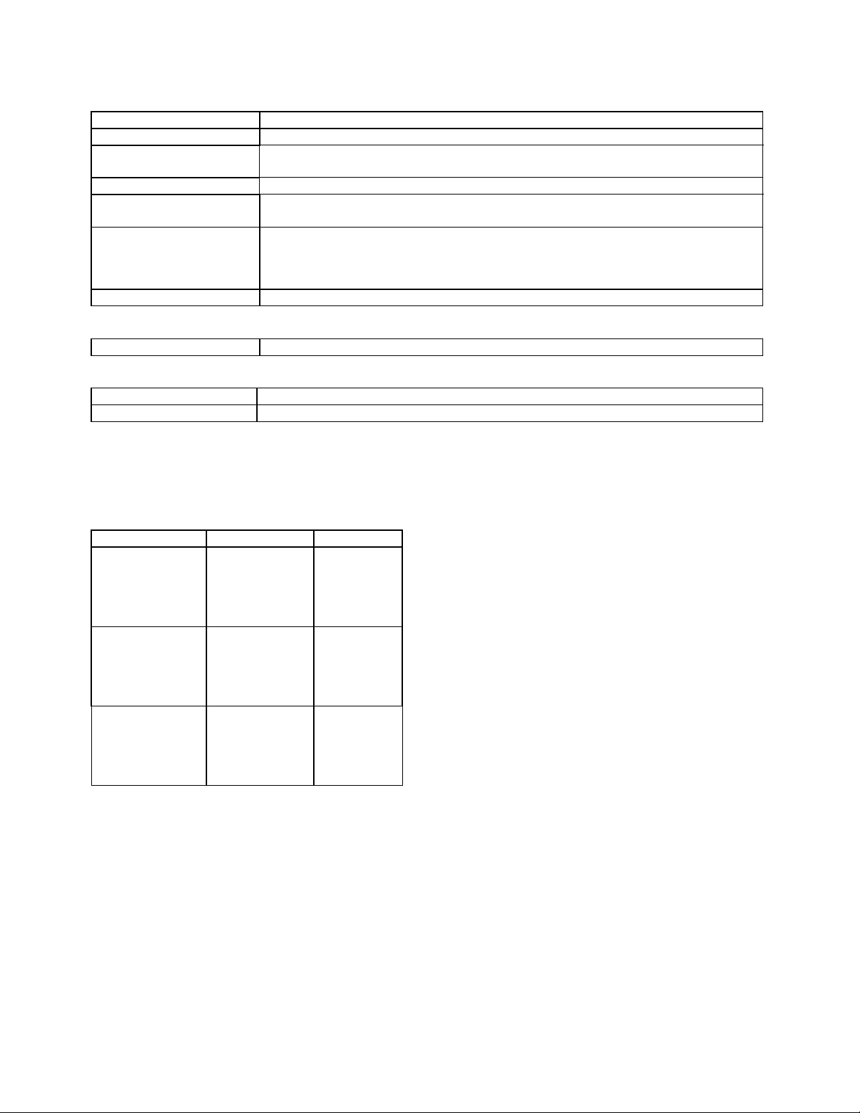
T-96SR General Specifications
The following general specifications are subject to change without notice.
GENERAL
VHF UHF 900 MHz
Frequency 132 - 174 MHz 380 - 512 MHz 928 - 960 MHz
Channel bandwidth 12.5 or 25 kHz 12.5 or 25 kHz 12.5 or 25 kHz
Operating temperature -30°C to +60°C
Supply voltage 10 - 16 VDC (applied through the interface connector)
RX Current at 13.3 VDC 150 mA 125 mA 135 mA
TX Current at 13.3 VDC 2.1 A 2.5 A 2.8 A
RX/TX bandwidth 18 MHz (132 - 150)
Nominal Dimensions 2.212” (H) x 3.25” (W) x 4.585” (L)
Shipping Weight 1.20 lbs (0.55 Kg)
RF connector SMA-F
Interface connector DE-15F high density D-subminiature
RECEIVER
VHF UHF 900 MHz
Selectivity (25 kHz)
Selectivity (12.5 kHz)
Intermodulation
Spurious rejection
Conducted spurious < -57 dBm maximum
* per TIA 603 with psophometrically weighted filter
TRANSMITTER
VHF UHF 900 MHz
Power output 1 - 5 watts 1 - 5 watts 1 - 5 watts
Spurious and harmonics -73dBc (-36 dBm) max -73dBc (-36 dBm) max -57 dBc (-20 dBm) max
Frequency stability 2.5 ppm
Duty cycle 50% at full power, 30 seconds maximum transmit time
* per TIA 603 with psophometrically weighted filter
*
16 MHz except
24 MHz (150 - 174)
70 dB minimum 65 dB minimum
60 dB minimum 70 dB minimum
70 dB minimum 60 dB minimum
70 dB minimum 70 dB minimum
*
20 MHz (450 - 470)
1.5 ppm
32 MHz
-57 dB max
001-4006-101
1-12
MODEM OPERATION
Interface EIA RS-232C
Operation Simplex/half duplex
Data rates 12.5 KHz Channels 4800, 9600 bps
25 KHz Channels 4800, 9600, 19200 bps
Modulation type DRCMSK
RTS/CTS delay
(Online diagnostics OFF)
*
Bit error rate
better than 1 x 10
better than 1 x 10
better than 2 x 10
5
–
at 1.0 µV at 9600 b/s half channel
6
–
at 1.0 µV at 9600 and 4800 b/s full channel
5
–
at 1.7 µV at 19200 b/s full channel
30 ms
Protocol Transparent to the user
DISPLAY and CONTROLS
3 status LEDs RX, TX, PWR
DIAGNOSTICS
Online Supply voltage, internal temperature, forward and reverse power, RS S I
Offline As for online, plus analog supply voltage, transmit test ton es
PROGRAMMABLE FEATURES
30 second timeout timer enable, bit rate, word length, parity, compatibility modes, frequency, channel, diagnostics on/off.
FCC / IC
CERTIFICATIONS
FCC IC (DOC)
VHF 2424016-001 2984195430A
(9K30F1D)
UHF
(15K3F1D)
900 MHz
(15K3F1D)
2424046-001
(9K30F1D)
(15K3F1D)
2424096-001
(9K30F1D)
(15K3F1D)
(15K0F1D)
(16K0F1D)
(11K0F1D)
(9K30F1D)
2984195432A
(9K30F1D)
(11K0F1D)
(16K0F1D)
2984195431A
(9K30F1D)
(11K0F1D)
(15K3F1D)
(16K0F1D)
*Subject to change.
001-4006-101
1-13
SECTION 2
OPERATION AND CONNECTION
2.1 INTRODUCTION
2.1.1 GENERAL
This section outlines the operation and connections of the T-96SR.
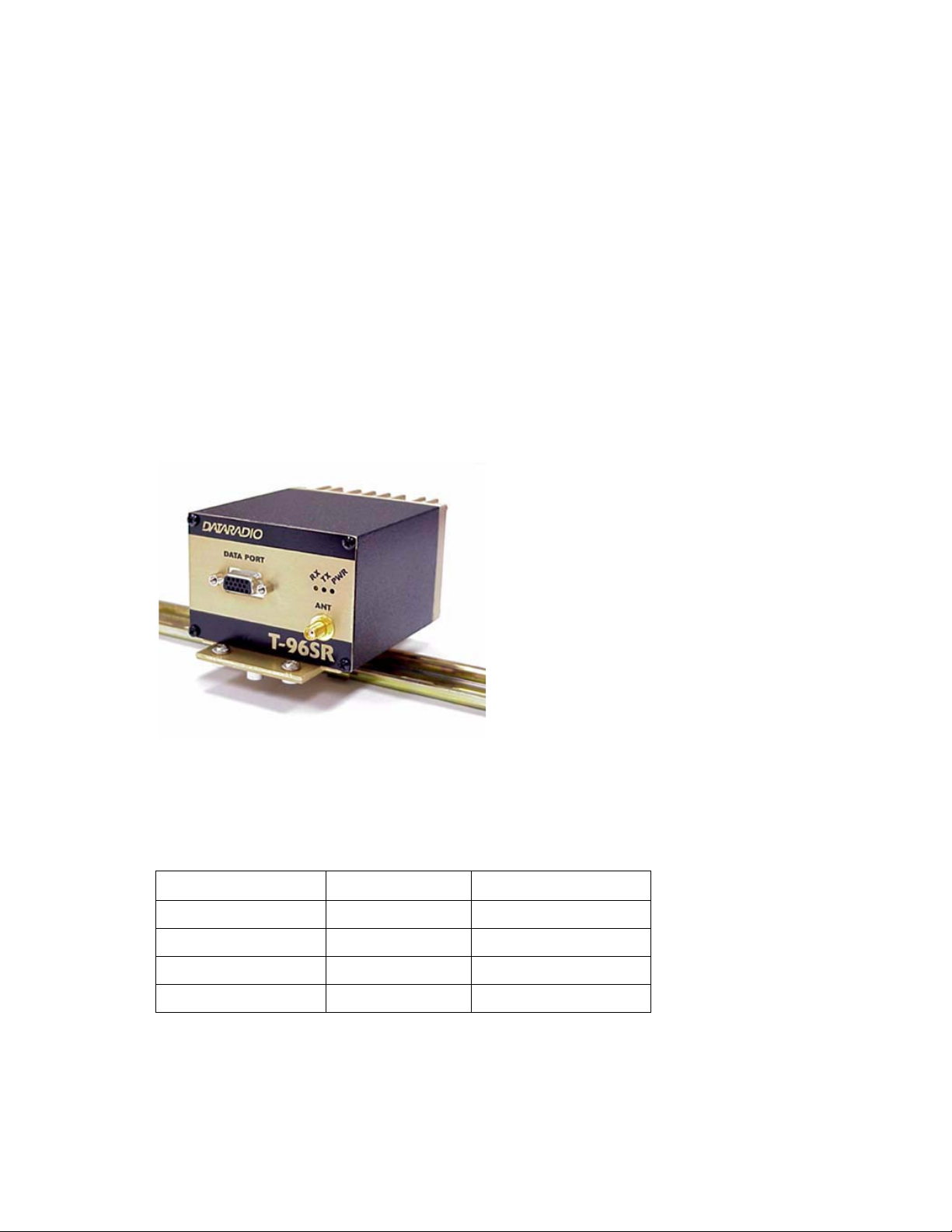
2.2 FRONT PANEL
2.2.1 INTRODUCTION
The front panel includes one SMA female an tenna conn ec tor, three LED indicators (see Table 2-1), and one
DE-15F interface (includes power connections).
Figure 2-1 T-96SR Front Panel
2.2.2 LED INDICATORS
Table 2-1 LED Indicators
LED Indicates Description
Green Power DC Power is applied
Flashing green Setup mode Unit is in setup mode
Red Transmit Unit is transmitting signal
Yellow Receive Unit is receiving signal
2-1
001-4006-101
 Loading...