

Dataradio T-96H Technical Manual

T-96H
Radio Modem
Technical Manual
version 0.01
PRELIMINARY
Copyright
August 1998
part no.: 120 10504-001
DATARADIO
Inc.
The entire contents of this manual and the Radio Service Software
described in this manual are copyright 1998 by
DATARADIO
Inc.

Table of Contents
1. PRODUCT OVERVIEW................................................................................................................................... 1
NTENDED AUDIENCE
1.1 I
NTRODUCTION
1.2 I
ENERAL DESCRIPTION
1.3 G
HYSICAL DESCRIPTION
1.4 P
ONFIGURATION
1.5 C
ATALOG NUMBERS
1.6 C
ACTORY TECHNICAL SUPPORT
1.7 F
RODUCT WARRANTY
1.8 P
EPLACEMENT PARTS
1.9 R
....................................................................................................................................... 1
................................................................................................................................................. 1
.................................................................................................................................... 1
.................................................................................................................................... 1
............................................................................................................................................... 1
......................................................................................................................................... 2
........................................................................................................................ 2
...................................................................................................................................... 2
....................................................................................................................................... 2
1.9.1 Factory Repair ........................................................................................................................................ 2
1.10 D
IAGNOSTICS AND REMOTE COMMANDS
..................................................................................................... 3
1.10.1 Addressing .......................................................................................................................................... 3
1.10.2 Online Diagnostics ............................................................................................................................. 3
1.10.3 Offline Diagnostics ............................................................................................................................. 4
1.10.4 Remote Commands ............................................................................................................................. 4
1.11 N
ETWORK CONFIGURATION
.......................................................................................................................... 4
1.11.1 Basic Network..................................................................................................................................... 4
1.11.2 Network Using T-Base........................................................................................................................ 5
1.11.3 Network Using T-Base Repeater......................................................................................................... 5
1.11.4 Network Using T-96H for Online Diagnostics.................................................................................... 6
2. FEATURES AND OPERATION...................................................................................................................... 7
VERVIEW
1.1 O
NTENDED AUDIENCE
2.1 I
RONT PANEL
2.2 F
........................................................................................................................................................ 7
....................................................................................................................................... 7
................................................................................................................................................... 7
2.2.1 LED Indicators........................................................................................................................................ 7
2.3 DTE P
ORT INTERFACE
..................................................................................................................................... 7
2.3.1 RS-232 Inteface Signal Levels................................................................................................................. 7
2.3.2 Interface Port .......................................................................................................................................... 8
2.3.3 Interface Signal Description ................................................................................................................... 8
HANNEL SELECTION
2.4 C
2.5 O
PERATION
....................................................................................................................................................... 9
....................................................................................................................................... 9
2.5.1 RTS/CTS Timing.................................................................................................................................... 10
2.5.2 XTAL mode............................................................................................................................................ 10
2.5.3 Extended Turnoff................................................................................................................................... 10
3. ADJUSTMENTS AND MAINTENANCE ..................................................................................................... 11
VERVIEW
1.1 O
NTENDED AUDIENCE
3.1 I
QUIPMENT REQUIRED
3.2 E
3.3 M
AINTENANCE INTERVALS
3.4 T96H A
...................................................................................................................................................... 11
..................................................................................................................................... 11
................................................................................................................................... 11
DJUSTMENTS
...................................................................................................................................... 11
3.4.1 Preliminary Verification ....................................................................................................................... 11
3.4.2 Basic Adjustments ................................................................................................................................. 11
3.4.3 Tests & ajustments................................................................................................................................. 11
3.4.4 Opening the Unit................................................................................................................................... 14
3.4.5 Location of Adjustments and Test Points.............................................................................................. 14
3.4.5.1 All Models, Logic PCB.................................................................................................................................14
4. LOADER/MODEM BOARD CIRCUIT DESCRIPTION............................................................................ 14
4.1 GENERAL..................................................................................................................................................... 14
............................................................................................................................. 11
i

4.2 TRANSMIT DATA....................................................................................................................................... 14
4.3 RECEIVE DATA........................................................................................................................................... 15
4.4 SYNTHESIZER PROGRAMMING.............................................................................................................. 15
4.5 POWER SUPPLIES ...................................................................................................................................... 15
4.6 MISCELLANEOUS FUNCTIONS ............................................................................................................... 15
5. SPECIFICATIONS.......................................................................................................................................... 17
INDEX........................................................................................................................................................................ 19
IGURE
F
IGURE
F
IGURE
F
IGURE
F
IGURE
F
IGURE
F
IGURE
F
ABLE
1 - RS-232 S
T
ABLE
T
2 - C
ABLE
T
3 - RTS / CTS D
ABLE
T
4 - E
ABLE
5: T
T
ABLE
6: T
T
ASIC NETWORK
1 - B
ETWORK USING
2 - N
SING A
3 - U
4 - N
5 - D
6 - DIP
7 - L
HANNEL SELECTION
XTENDED TURNOFF DELAYS
ESTS AND ADJUSTMENTS
ESTS AND ADJUSTMENTS
T-B
ETWORK WITH MONITORING SITE
ATA
I/O C
SWITCH LOCATION
OGIC BOARD ADJUSTMENTS AND TEST POINTS
IGNAL LEVELS
.......................................................................................................................................... 4
ASE
T-B
ASE REPEATER
............................................................................................................................ 5
......................................................................................................................... 5
.............................................................................................................. 6
ONNECTOR PINOUT
................................................................................................................... 7
................................................................................................................................9
.................................................................................................................................. 7
.................................................................................................................................... 9
ELAYS
.................................................................................................................................... 10
..................................................................................................................... 10
FULL CHANNEL
HALF CHANNEL
....................................................................................... 14
UNITS
(25 KHZ & 30 K
UNITS
(12.5 KHZ & 15 K
HZ MODELS
HZ MODELS
)........................................ 12
)..................................... 13
ii

What's New in Version 0.01
First version of the T-96H technical manual based on the latest T-
•
96S technical manual ver 2.01.
History
Version 0.01:
Preliminary version.
•
iii

Definitions
The following terms are used throughout this document.
Item Definition
Bit dribble Extraneous bits delivered at the end of a data transmission. Equivalent to a
“squelch tail” in voice systems.
DCE Data Communications Equipment. This designation defines the direction (input
or output) of the various RS-232C interface signals. Modems are always wired as
DCE. See also DTE.
DTE Data Terminal Equipment. This designation defines the direction (input or out-
put) of the various RS-232C interface signals. Most telemetry and SCADA
equipment, as well as PCs, are wired as DTE. See also DCE.
HDX Half Duplex. A unit which uses separate transmit and receive frequencies, but
which may not transmit and receive simultaneously.
OFLNDIAG Offline Diagnostics software. This software allows local (T-96S only) and re-
mote diagnostics (T-96S and RNET 9600S).
ONDMON Online Diagnostics Monitor software. This software allows online diagnostics
monitoring of T-96S/DL3276 and RNET 9600S.
PLC Programmable Logic Controller. An intelligent device that can make decisions,
gather and report information, and control other devices.
RS-232 Industry–standard interface for low speed data transfer (EIA-RS-232E).
RSS Radio Service Software. This software allows configuration and testing of the
T-96S (T96RSS).
RTS Request To Send. An RS-232C signal used by most SCADA equipment to initi-
ate a data transmission.
RTU Remote Terminal Unit. A SCADA device used to gather information or control
other devices.
SCADA Supervisory Control And Data Acquisition. A general term referring to systems
that gather data and/or perform control operations.
Simplex A unit which uses the same frequency for transmit and receive.
Transparent A transparent unit transmits all data without regard to special characters, etc.
T-96S The
DATARADIO
T-96S Telemetry Radiomodem. The T-Base is made up of 2 or
3 modified T-96S units.
DL-3276 The Johnson Data Telemetry (JDT) version of the T96S.
T-96H Enhence version of the T-96S capable of 19200 b/s in full channel radio and
9600 b/s in half channel radio models.
iv

1. PRODUCT OVERVIEW
This document provides the information
required for the selection, installation, operation and maintenance of the
DATARADIO
T-96H radiomodem.
1.1 Intended Audience
This document is designed for use by engineering design, installation, and maintenance personnel.
1.2 Introduction
This chapter provides the information necessary to identify and assess the capabilities
of the T-96H. Connection and operation are
also described.
1.3 General Description
The T-96H is a transparent real-time radiomodem designed primarily for SCADA and
telemetry use. The T-96H is available in
different versions according to radio frequency. Common features to all versions
include:
• Data speeds of 4800 to 19200 b/s
(9600 b/s maximum in half channels)
using standard RS-232 interface.
• Built–in 8 channel synthesized radio
transceiver for VHF, UHF and
900 MHz.
• Power output of 1W to 5W (software
controlled).
• Half duplex or simplex operation.
• Transmit switching via RTS.
• On-line diagnostics monitoring
• Offline local and remote diagnostics.
• Compatible with
for base station or repeater use.
• Compatible with any
DATARADIO
Interoperability Standard
equipment for data rate up to 9600 b/s.
DATARADIO
(DIOS)
T-Base
I
NTEROP ERAB IL ITY
®
1.4 Physical Description
The T-96H consists of a logic PCB (which
includes the modem circuitry) and a separate radio module. The two boards plug directly together and slide into the rails of an
extruded aluminum case. The front panel
includes the DE-15 data connector and a
SMA antenna connector, as well as three
LED indicators. Power connections are
made through the DE-15 data connector.
The unit is not hermetically sealed and
should be mounted in a suitable enclosure
where dust and/or a corrosive atmosphere
are anticipated. There are no external
switches or adjustments. Operating parameters are set using software.
Channel selection may be done using an
internal DIP switch, by strapping the appropriate pins on the DE-15 data connector, or
by selecting the desired channel using the
T96HRSS or the OFLNDIAG.
1.5 Configuration
Operating characteristics of the T-96H are
configured by means of
(T96HRSS - p/n 085 03250-xxx)
ware
available from your sales representative.
Also available is the
software (OFLNDIAG) and the
agnostics Monitor
access to offline diagnostics & commands
(local and remote) and online diagnostics
monitoring with or without a T-Base. Both
programs are MSDOS based and will run on
any 486 or higher PC (2 Megabytes memory
required).
The T-96H requires the use of the
T96HRSS for both configuration and adjustment.
Radio Service Soft-
Offline Diagnostics
Online Di-
(ONDMON) which give
120 10503-201 PRELIMINARY T-96S Technical Manual
1
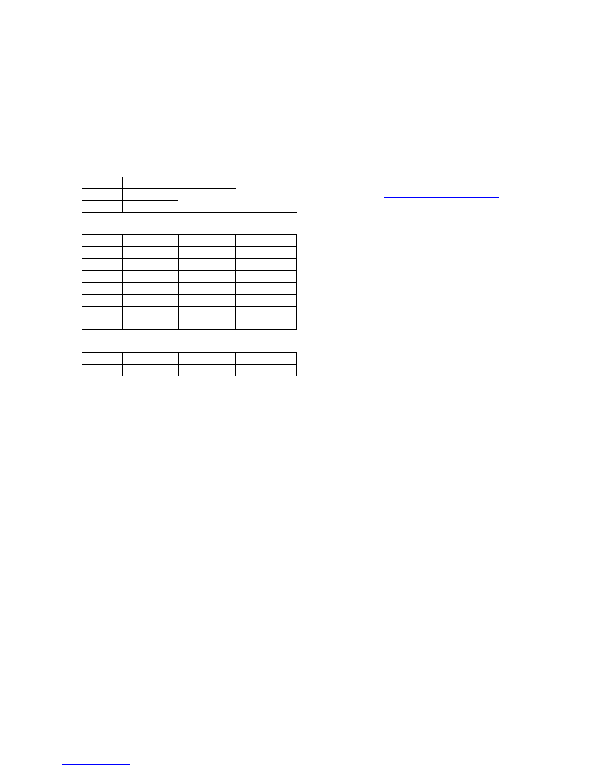
1.6 Catalog Numbers
A T-96H may be identified from its catalog
number.
CATALOG NUMBERS
Format is TH[radio][band][channel spacing]0
radio
22
12
92
(frequencies in MHz)
band
1
2
3
4
5
6
7
8
channel spacing (
1
3
For example, a TH12530 is a UHF, 450-470 MHz unit with
25 kHz channel spacing.
VHF
UHF
900
380 - 403
403 - 419
419 - 435
132 – 150 435 - 451
150 – 174 450 - 470 928 - 960
464 - 480
480 - 496
496 - 512
frequencies in MHz
15.0 12.5 12.5
30.0 25.0 25.0
)
1.7 Factory Technical
Support
The Technical Support departments of
DATARADIO
(JDT) provide customer assistance on technical problems and serve as an interface
with factory repair facilities. They can be
reached in the following ways:
DATARADIO Inc.
5500 Royalmount Ave, suite 200
Town of Mount Royal
Quebec, Canada H4P 1H7
Technical support hours: Monday to Friday
9:00 AM to 5:00 PM, Eastern Time,.
phone: +1 514 737-0020
fax: +1 514 737-7883
Email address: support@dataradio.com
Johnson Data Telemetry Corp.
and Johnson Data Telemetry
Customer Service Department
299 Johnson Avenue, P.O. Box 1733
Waseca, MN 56093-0833
Technical support hours: Monday to Friday
9:00 AM to 5:00 PM, Central Time,.
phone: 800 992-7774 and
+1 507 835-6911
fax: 507 835-6969
Email address: support@johnsondata.com
1.8 Product Warranty
Warranty information may be obtained by
contacting your sales representative.
1.9 Replacement Parts
This product is normally not field serviceable, except by the replacement of complete
units. Specialized equipment and training is
required to repair logic boards and radio
modules.
Contact Technical Support for service information before returning equipment. A
Technical Support representative may suggest a solution eliminating the need to return
equipment.
1.9.1 Factory Repair
When returning equipment for repair, you
must request an RMA (Returned Material
Authorization) number. The Tech Support
representative will ask you several questions
to clearly identify the problem. Please give
the representative the name of a contact person who is familiar with the problem,
should questions arise during servicing of
the unit.
Customers are responsible for shipping
charges for returned units. Units in warranty
will be repaired free of charge unless there
is evidence of abuse or damage beyond the
terms of the warranty. Units out of warranty
will be subject to service charges. Information about these charges is available from
Technical Support.
120 10503-201 PRELIMINARY T-96S Technical Manual
2

1.10 Diagnostics and
Remote Commands
Diagnostics and remote commands are
processed using the T96H Offline Diagnostics software (OFLNDIAG). Diagnostics
can be monitored using the T96H Online
Diagnostics Monitor program (ONDMON).
Short ID: This value is the low order 10 bits
of the
online diagnostics only. It may not be
modified directly using the T96HRSS; it
is always derived from the
All units within a network should have
unique
biguity in Online Diagnostics reports.
ID Number
Short ID
. It is used to identify
ID Number
numbers to avoid am-
.
The T-96H has the following diagnostic and
command features:
Online diagnostics. Information is auto-
matically sent by each unit at the beginning of every transmission. May be disabled for back compatibility with
DATARADIO
RNET 9600.
Offline diagnostics. Information is sent by a
specific unit in response to an inquiry
by the master or monitoring station.
Remote commands. Commands may be sent
by the master or monitoring station to
any specific remote unit.
T-Modem 96 or Motorola
1.10.1 Addressing
Each T-96H has addressing capability which
is used for diagnostics and remote commands only. Two addresses are used:
ID Number: This value (maximum 1023) is
assigned at the factory but may be modified using the T96RSS. The
is used to uniquely identify the T-96H
for remote commands and offline diagnostics. The
ues within the range of 1 to 99,999,999
but multiples of 1024 should not be
used.
ID Number
ID Number
may have val-
Either the T96HRSS or OFLNDIAG may be
used to check the value of the
When setting up a network, we recommend
checking each unit to make sure that there is
no duplication of
cations may be resolved by changing the
Number
If
within the range of 1 to 1023, the
ber
same value. Customers may find this to be a
convenience.
.
ID Numbers
and the
Short ID
are set so that their value is
Short ID
numbers. Dupli-
will always have the
Short ID
ID
ID Num-
1.10.2 Online Diagnostics
Online diagnostics (statistics) require the
use of a network configuration such as that
specified in section 1.11.2. or 1.11.4 Online
diagnostics do not interfere with normal
network operation. The following information is gathered:
• Supply voltage
• Internal temperature
• Forward and reverse power in watts
(T96S models only)
• Received signal strength in dBm
Each T-96H can accumulate these statistics
for the last 15 stations heard. The accumulated values may be displayed using the
OFLNDIAG or dynamically monitored by
the Online Diagnostics Monitor program
(ONDMON).
.
120 10503-201 PRELIMINARY T-96S Technical Manual
3
 Loading...