

Dataradio Paragon-III User Manual

Paragon-III (700MHz)
Data Base Station
(With Amplifier Technologies 70W PA)
User Manual
Version 1.00a
Preliminary – For Internal Use Only
The entire contents of this manual are copyright 2005 by DATARADIO Inc.
Copyright DATARADIO Inc.
April 2005
Part no.: 120 20191-100a
i

1. PRODUCT OVERVIEW...................................................................................................................................1
1.1 INTENDED AUDIENCE........................................................................................................................................1
1.2 GENERAL DESCRIPTION.....................................................................................................................................1
1.2.1 Features...................................................................................................................................................2
1.2.2 Configuration...........................................................................................................................................2
1.3 FACTORY TECHNICAL SUPPORT ........................................................................................................................3
1.4 PRODUCT WARRANTY.......................................................................................................................................4
1.5 REPLACEMENT PARTS .......................................................................................................................................4
1.5.1 Factory Repair.........................................................................................................................................4
1.6 PACKAGING.......................................................................................................................................................4
2. INSTALLATION................................................................................................................................................5
2.1 OVERVIEW ........................................................................................................................................................5
2.2 LOCATION .........................................................................................................................................................5
2.3 FRONT VIEW .....................................................................................................................................................5
REAR VIEWS ..............................................................................................................................................................7
2.5 ELECTRICAL......................................................................................................................................................8
2.5.1 Paragon-III Assembly Power ..................................................................................................................8
2.6 POWER AMPLIFIER ............................................................................................................................................9
2.7 ANTENNA........................................................................................................................................................10
2.7.1 Overview................................................................................................................................................10
2.7.2 Cabling and Connection........................................................................................................................10
2.8 COMPLETING THE PHYSICAL INSTALLATION....................................................................................................10
2.9 CHECKING OUT NORMAL OPERATION .............................................................................................................10
3. OPERATING DESCRIPTION .......................................................................................................................11
3.1 RADIO ASSEMBLY...........................................................................................................................................11
Diversity SDR Rx module ...................................................................................................................................11
3.1.2 5W Transmitter module .........................................................................................................................12
3.1.3 70W Power Amplifier ............................................................................................................................12
3.1.4 BSC module ...........................................................................................................................................13
3.1.5 Speaker panel ........................................................................................................................................ 13
3.1.6 Power Supply Modules..........................................................................................................................14
3.1.7 Radio Backplane Assembly....................................................................................................................16
3.2 ONLINE & OFFLINE DIAGNOSTICS...................................................................................................................16
4. OPERATION & CONFIGURATION............................................................................................................17
4.1 BROWSER-BASED SETUP AND STATUS............................................................................................................17
4.2 DEFAULT IP SETTINGS .................................................................................................................................... 17
4.2.1 Ethernet Interface 1 (DATA)..................................................................................................................17
4.2.2 Ethernet Interface 2 (SETUP)................................................................................................................17
4.2.3 RF Interface...........................................................................................................................................17
4.3 IP NETWORK SETTINGS...................................................................................................................................18
4.3.1 IP Network Settings (with Host) ............................................................................................................18
4.3.2 IP Network Settings (with Router).........................................................................................................18
4.4 LAN SETUP.....................................................................................................................................................19
4.5 LOGIN SCREEN ................................................................................................................................................19
4.5.1 Initial Installation Login........................................................................................................................19
4.6 SECURITY SETUP.............................................................................................................................................20
4.7 INTERFACE ......................................................................................................................................................20
4.7.1 Apply Parameters & Save Parameters Buttons Behavior .....................................................................21
4.7.2 Unit Status.............................................................................................................................................22
120 40515-100a HiPR900 User Manual
ii

5. TROUBLE-SHOOTING AND TESTING .....................................................................................................26
5.1 EQUIPMENT REQUIRED....................................................................................................................................26
5.2 RECOMMENDED CHECKS.................................................................................................................................26
5.3 ADDITIONAL TEST DETAILS .............................................................................................................................30
5.3.1 RF Data Link Test..................................................................................................................................30
5.4 WINDOWS/UNIX TOOLS ..................................................................................................................................31
5.4.1 Network Connectivity.............................................................................................................................31
5.4.2 Configuration Information ....................................................................................................................31
5.4.3 Statistics Information.............................................................................................................................32
6. RADIO PROGRAMMING AND ADJUSTMENTS .....................................................................................33
6.1 T881-10 RADIO TRANSMITTER PROGRAMMING..............................................................................................33
6.1.1 Recommended Items ..............................................................................................................................33
6.1.2 T881-10 Module Programming.............................................................................................................33
6.1.3 Channel Selection via DIP Switches......................................................................................................35
6.2 TRANSMITTER RADIO TUNING ........................................................................................................................36
6.2.1 Test Equipment......................................................................................................................................36
6.2.2 Transmitter Module (T881-10-02200)...................................................................................................36
7. SPECIFICATIONS ..........................................................................................................................................39
FIGURE 1 - TYPICAL RACK-MOUNT MULTI-MODULES "RADIO ASSEMBLY" ....................................................................5
FIGURE 2 – AMPLIFIER TECHNOLOGIES INC 70W POWER AMPLIFIER............................................................................6
FIGURE 3 - INDICATORS AND POWER ADJUSTMENT CONTROL .......................................................................................6
FIGURE 4 – POWER AMPLIFIER’S DC POWER AND RF CONNECTORS.............................................................................6
FIGURE 5 - PARAGON-III REAR VIEW .............................................................................................................................7
FIGURE 6 - BACKPLANE .................................................................................................................................................7
FIGURE 7 - MAXI-FUSE ..................................................................................................................................................9
FIGURE 8 - RECEIVER MODULE.....................................................................................................................................11
FIGURE 9 – 5W EXCITER MODULE ...............................................................................................................................12
FIGURE 10 - BSC MODULE...........................................................................................................................................13
FIGURE 11 - SPEAKER MODULE ....................................................................................................................................13
FIGURE 12 - T-809 POWER SUPPLY MODULE...............................................................................................................14
FIGURE 13 - T809 REAR PANEL....................................................................................................................................15
FIGURE 14 - RADIO BACKPLANE ASSEMBLY................................................................................................................16
FIGURE 15 - IP NETWORK SETTINGS IN ROUTER MODE (WITH HOST)..........................................................................18
FIGURE 16 - IP NETWORK SETTINGS IN ROUTER MODE (WITH ROUTER) .....................................................................18
FIGURE 17 - ENTER NETWORK PASSWORD SCREEN – ETH1 DATA PORT SHOWN ........................................................19
FIGURE 18 - WEB USER INTERFACE (PRELIMINARY – HIPR-900 MODEL SHOWN).......................................................20
FIGURE 19 - PARAMETER COMMAND BUTTONS BEHAVIOR..........................................................................................21
FIGURE 20 - STATION RESET CONFIRMATION ..............................................................................................................21
FIGURE 21 - EXCITER SYSTEM INFOMATION SAMPLE...................................................................................................34
FIGURE 22 - EXCITER CHANNEL INFORMATION SAMPLE..............................................................................................34
FIGURE 23 - BACKPLANE DIP SWITCHES EXAMPLE - CHANNEL 1 SELECTED................................................................35
FIGURE 24 - T881-0200 TRANSMITTER TUNING CONTROLS LOCATION .......................................................................38
TABLE 1 - ON-AIR DATA SPEEDS AND MODULATION TYPES ............................................................................................2
TABLE 2 - 70W POWER AMPLIFIER INDICATORS..........................................................................................................12
TABLE 3 - UNIT STATUS...............................................................................................................................................22
TABLE 4 - SETUP (GENERAL).......................................................................................................................................22
TABLE 5 - BASIC IP CONFIGURATION ..........................................................................................................................22
TABLE 6 - RF SETUP ....................................................................................................................................................22
TABLE 7 - TERMINAL SERVER CONFIGURATION...........................................................................................................22
TABLE 8 - ADVANCED IP CONFIGURATION..................................................................................................................23
120 40515-100a HiPR900 User Manual
iii

TABLE 9 - RF NETWORK SETUP...................................................................................................................................23
TABLE 10 - BROADCAST / MULTICAST.........................................................................................................................23
TABLE 11 - IP OPTIMIZATION & TUNING.....................................................................................................................24
TABLE 12 - SIMPLE NETWORK TIME PROTOCOL ..........................................................................................................24
TABLE 13 - SECURITY ..................................................................................................................................................24
TABLE 14 - NETWORK..................................................................................................................................................24
TABLE 15 - PACKET STATISTICS...................................................................................................................................25
TABLE 16 - RF TEST ....................................................................................................................................................25
TABLE 17 - FTP TRANSFER..........................................................................................................................................25
TABLE 18 - RSSI TABLE ..............................................................................................................................................25
TABLE 19 - MANUALS & SUPPORT...............................................................................................................................25
TABLE 20 - CHECKLIST A (AFTER INSTALLATION) ......................................................................................................27
TABLE 21 - CHECKLIST B (GENERAL)..........................................................................................................................28
120 40515-100a HiPR900 User Manual
iv

WHAT'S NEW
History
Version 1.00a: April 2005 – Preliminary,
- With optional Amplifier Technologies 70W PA
Version 0.02: October 2004 – issue 0.02, preliminary.
- With optional Aethercomm 50W PA as Annex A.
Version 0.01: April 2004 –first issue, preliminary
120 40515-100a HiPR900 User Manual
v

About Dataradio
Dataradio is a leading designer and manufacturer of advanced wireless data products and systems for mission critical applications. Our products are found at the heart of mobile data and SCADA networks
around the world.
With over 20 years dedicated to data technology and innovation, Dataradio is the premier source for
wireless data solutions. Our products include mobile data products, telemetry devices, integrated wireless
modems for fixed point-to-point and point to multi-point applications, and OEMs. Our product line is one
of the broadest in the industry covering the most often-used frequency bands.
www.dataradio.com
Dataradio provides product brochures, case studies software downloads and product information on our
website. Every effort is taken to provide accurate, timely product information in this user manual.
Product updates may result in differences between the information provided herein and the product
shipped. The information in this document is subject to change without notice.
DATARADIO is a registered trademark, Gemini-G3, Paragon, Paragon PD, Paragon-III and PARALLEL
DECODE are trademarks of Dataradio Inc
120 40515-100a HiPR900 User Manual
vi

Definitions
Access Point Communication hub for users to connect to a wired LAN. APs are important for
providing heightened wireless security.
AES Advanced Encryption Standard (AES) - uses 128-bit encryption to secure data.
Airlink Physical radio frequency connections used for communications between units.
ARP Address Resolution Protocol – Maps Internet address to physical address.
Asynchronous Information that can be sent at random times, and not synchronized to a clock.
Transmission characters begin with a “start” bit and end with a “stop” bit.
AVL Automatic Vehicle Location. Optional feature that involves using GPS (Global
Positioning System) signals from the mobile unit by the Host PC.
Backbone The part of a network that connects most of the systems and networks together,
and handles the most data.
Bandwidth The transmission capacity of a given device or network.
Browser An application program that provides a way to look at and interact with all the in-
formation on the World Wide Web.
BSC Base Station Controller - An async controller-modem designed for the radio base
station in mobile systems. A component of Paragon-III™.
CDip Windows based "Commands & Data over IP" radio-modem Software. This soft-
ware allows basic tests, unit configuration, and troubleshooting.
COM Port RS-232 serial communications ports of the Paragon-III wireless radiomodem.
Default Gateway A device that forwards Internet traffic from your local area network.
DHCP Dynamic Host Configuration Protocol - A networking protocol that allows ad-
ministrators to assign temporary IP addresses to network computers by "leasing"
an IP address to a user for a limited amount of time, instead of assigning permanent IP addresses.
DNS Domain Name Server - translates the domain name into an IP address.
Domain A specific name for a network of computers.
Dynamic IP Addr A temporary IP address assigned by a DHCP server.
E-DBA Dataradio’s Enhanced Dynamic Bandwidth Allocation airlink protocol.
Ethernet IEEE standard network protocol that specifies how data is placed on and re-
trieved from a common transmission medium.
Firewall A set of related programs located at a network gateway server that protects the
resources of a network from users from other networks.
Firmware The programming code that runs a networking device.
Fragmentation Breaking a packet into smaller units when transmitting over a network medium
that cannot support the original size of the packet.
FTP File Transfer Protocol - A protocol used to transfer files over a TCP/IP network.
120 40515-100a HiPR900 User Manual
vii

Gateway A device that interconnects networks with different, incompatible communica-
tions protocols.
Gemini-G3 High specs dual DSP mobile radiomodem with Dataradio Parallel Decode™
technology
HDX Half Duplex. Data transmission that can occur in two directions over a single
line, using separate Tx and Rx frequencies, but only one direction at a time.
HTTP HyperText Transport Protocol - The communications protocol used to connect to
servers on the World Wide Web.
IPCONFIG A Windows 2000 and XP utility that displays the IP address for a particular net-
working device.
MAC Media Access Control - The unique address that a manufacturer assigns to each
networking device.
NAT Network Address Translation - NAT technology translates IP addresses of a local
area network to a different IP address for the Internet.
Network A series of computers or devices connected for the purpose of data sharing, stor-
age, and/or transmission between users.
Network speed This is the bit rate on the RF link between units.
Node A network junction or connection point, typically a computer or work station.
OIP Optimized IP – Compresses TCP and UDP headers, and filters unnecessary ac-
knowledgments. This makes the most use of the available bandwidth.
OTA Over-The-Air - Standard for the transmission and reception of application-related
information in a wireless communications system
Paragon-III IP-based data radio base station used in mobile networks and designed specifi-
cally to fit the needs of vehicular applications. Runs up to 128 kb/s
Parallel Decode Technology featuring dual receivers for added data decode sensitivity in multi-
path and fading environments.
Ping Packet INternet Groper - An Internet utility used to determine whether a particu-
lar IP address is online.
PLC Programmable Logic Controller. An user-provided intelligent device that can
make decisions, gather and report information, and control other devices.
Router A networking device that connects multiple networks together.
RS-232 Industry–standard interface for data transfer.
Static IP Address A fixed address assigned to a computer or device that is connected to a network.
Static Routing Forwarding data in a network via a fixed path.
Subnet Mask An address code that determines the size of the network.
Switch A data switch that connects computing devices to host computers, allowing a
large number of devices to share a limited number of ports.
Sync Data transmitted on a wireless network that keeps the network synchronized.
TCP Transmission Control Protocol - A network protocol for transmitting data that re-
quires acknowledgement from the recipient of data sent.
TCP/IP Transmission Control Protocol/Internet Protocol - A set of instructions PCs use
to communicate over a network.
Telnet A user command and TCP/IP protocol used for accessing remote PCs.
120 40515-100a HiPR900 User Manual
viii

TFTP Trivial File Transfer Protocol - A version of the TCP/IP FTP protocol that has no
directory or password capability.
Topology The physical layout of a network.
Transparent A transparent unit transmits all data without regard to special characters, etc.
UDP User Datagram Protocol - A network protocol for transmitting data that does not
require acknowledgement from the recipient of the data that is sent.
Upgrade To replace existing software or firmware with a newer version.
URL Universal Resource Locator - The address of a file located on the Internet.
VIS Vehicular Information Solutions. Dataradio’s name for a series of products spe-
cially designed for mobile data.
VPN Virtual Private Network - A security measure to protect data as it leaves one net-
work and goes to another over the Internet.
WINIPCFG A Windows 98 and Me utility that displays the IP address for a particular net-
working device.
WLAN Wireless Local Area Network - A group of computers and associated devices that
communicate with each other wirelessly.
120 40515-100a HiPR900 User Manual
ix

1. PRODUCT OVERVIEW
This document provides information required for the setting up, operation, testing and trouble-shooting of
the Dataradio® Paragon-III™
radio-modem base station.
1.1 Intended Audience
This document is intended for engineering, installation, and maintenance personnel.
1.2 General Description
The Paragon-III product is a factory-integrated industrial-grade IP-based data radio base station used in
mobile networks and is designed specifically to fit the needs of vehicular applications. The 700MHz version
features diversity Software Defined Radio (SDR) receivers for added data decode sensitivity in multi-path
and fading environments.
When used with Dataradio’s state-of-the-art Gemini-G3 mobile IP data solution, the system delivers
uneq u a l e d h i g h - spee d d a t a p e rformanc e and un matc h e d effective throughput.
All Paragon-III models are supplied in a rackmount configuration that includes:
• A Paragon-III full-duplex radio-modem assembly that includes a Next generation high-speed Dataradio
third generation “Base Station Controller” module (BSC) fitted in the radio chassis assembly.
• A 70W power amplifier (model SRA7070B) manufactured by Amplifier Technologies Inc. supplied in a
stand-alone rackmount configuration. It is DC-powered by the Paragon-III.
• Duplexer and backup power units are custom furnished items.
• Wire line modem(s) are optional items.
• Laptop PC and its application software are user-supplied items.
120 20191-100a Paragon-III User Manual
1

1.2.1 Features
• Parallel Decode (PD) technology featuring a diversity SDR receiver module for added decode
sensitivity in multi-path and fading environments.
• Fully IP based product line, using an optimized IP layer that reduces IP overhead for the RF link
• Sophisticated dual DSP-based modem design provides added system performance, fewer retries
and more effective throughput.
• 700MHz / 50kHz channels for the Public Safety band of operation:
766-773 MHz TX (under FCC part 90) and 762-764 MHz TX (under FCC part 27)
• Full duplex operation in the 700MHz frequency band
• Base Station with 70W RF Power Amplifier (user adjustable from 35W)
• On-air data speeds and modulation types supported:
Table 1 - On-air data speeds and modulation types
Modulation type Channel spacing – 50kHz
SRC4FSK
SRC8FSK
SRC16FSK
• Uses the Next generation high-efficiency Dataradio Enhanced-DBA over-the-air protocol
• Over-the-air compatible with Gemini-G3 mobile products
• Out-of-band signaling enables transmission of GPS reports with no effect on system performance.
64 kb/s
96 kb/s
128 kb/s
• Flash programmable firmwares, including over-the-air programming capability
• Paragon-III units are factory-configured based on each customer’s network system requirements
1.2.2 Configuration
Paragon-III units are factory-configured to default settings. Configuration changes or upgrades are webbased.
120 20191-100a Paragon-III User Manual
2

1.3 Factory Technical Support
The Technical Support departments of DATARADIO provide customer assistance on technical prob-
lems and serve as an interface with factory repair facilities. They can be reached in the following
ways:
For Canada and International customers:
DATARADIO Inc.
5500 Royalmount Ave, suite 200
Town of Mount Royal
Quebec, Canada H4P 1H7
Technical support hours: Monday to Friday 9:00 AM to 5:00 PM, Eastern Time
phone: +1 514 737-0020
fax: +1 514 737-7883
Email address: support@dataradio.com
or
For U.S. customers:
DATARADIO Corp.
6160 Peachtree Dunwoody RD., suite C-200
Atlanta, Georgia 30328
Technical support hours: Monday to Friday 9:00 AM to 5:00 PM, Eastern Time
phone: 1 770 392-0002
fax: 1 770 392-9199
Email address: drctech@dataradio.com
120 20191-100a Paragon-III User Manual
3

1.4 Product Warranty
Warranty information may be obtained by contacting your sales representative.
1.5 Replacement Parts
This product is usually not field-serviceable, except by the replacement of individual radio modules.
Specialized equipment and training is required to repair logic, modem boards, and radio modules.
Contact Technical Support for service information before returning equipment. A Technical Support
representative may suggest a solution eliminating the need to return equipment.
1.5.1 Factory Repair
When returning equipment for repair, you must request an RMA (Returned Material Authorization)
number. The Tech Support representative will ask you several questions to clearly identify the problem. Please give the representative the name of a contact person, who is familiar with the problem,
should a question arise during servicing of the unit.
Customers are responsible for shipping charges for returned units. Units in warranty will be repaired
free of charge unless there is evidence of abuse or damage beyond the terms of the warranty. Units
out of warranty will be subject to service charges. Information about these charges is available from
Technical Support.
1.6 Packaging
Each Paragon-III – 700MHz product normally leaves the factory packaged as follows:
• A Dataradio base station “Radio-modem assembly”
• A rackmount 70W power amplifier assembly
• One standard seven-foot 120VAC power cord
• DC power harness to connect the radio assembly to the power amplifier rackmount assembly.
Frequently, Paragon-III product components are field-assembled prior to customer delivery.
The cabinetry may then be supplied in one of several custom rack-mount configurations that may also include fan, backhaul modems, duplexer/filters/combiners, and ancillary equipment.
If damage has occurred to the equipment during shipment, file a claim with the carrier immediately.
120 20191-100a Paragon-III User Manual
4
2. Installation
2.1 Overview
The cabinet and rack-mount housing the Paragon-III’s radio-modem and Power Amplifier is
generally installed in a sheltered facility. Occasionally located adjacent to the nerve center of the
user’s network, it is often located near tower sites or at remote locations where it operates unattended.
Furnishings needed include power, cabling, and installation of antenna, landline or microwave modem, and host PC or portable computer. Details of these are outside the scope of this manual. This
manual covers the radio-modem assembly and the power amplifier.
2.2 Location
Be sure to place the Paragon-III in such a way that:
• The LEDs can be seen (as an aid in troubleshooting)
• Access to the antenna connector and to the back connectors is possible without removing the unit
• Sufficient air may flow around the unit to provide adequate cooling.
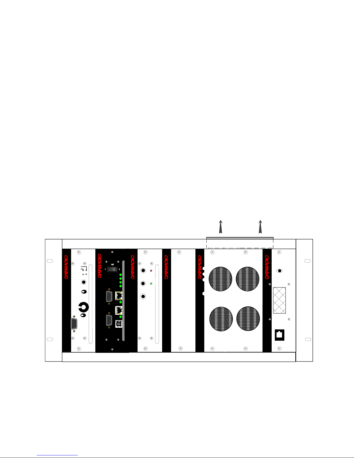
2.3 Front View
Model using Amplifier Technologies Inc power amplifier.
Figure 1 - Typical rack-mount multi-modules "Radio Assembly"
® ® ®
Diversity
SDR Rx
LOCK
PWR
RCVR
GATE
LEVEL
12
Volume
Norm -Mon
COM
®
® ®
BSC
COM 1
COM 2
PWR
STATUS
ETH 1
ETH 2
RX
TX
USB
2
1
Exciter
Carrier
Line
Sensitivity
Microphone
On
Supply
®
Power Supply Power Supply
Air Flow
Speaker Panel
SPEAKER
SELECT SWITCH
RX2RX1
OFF
programming
port
120 20191-100a Paragon-III User Manual
5
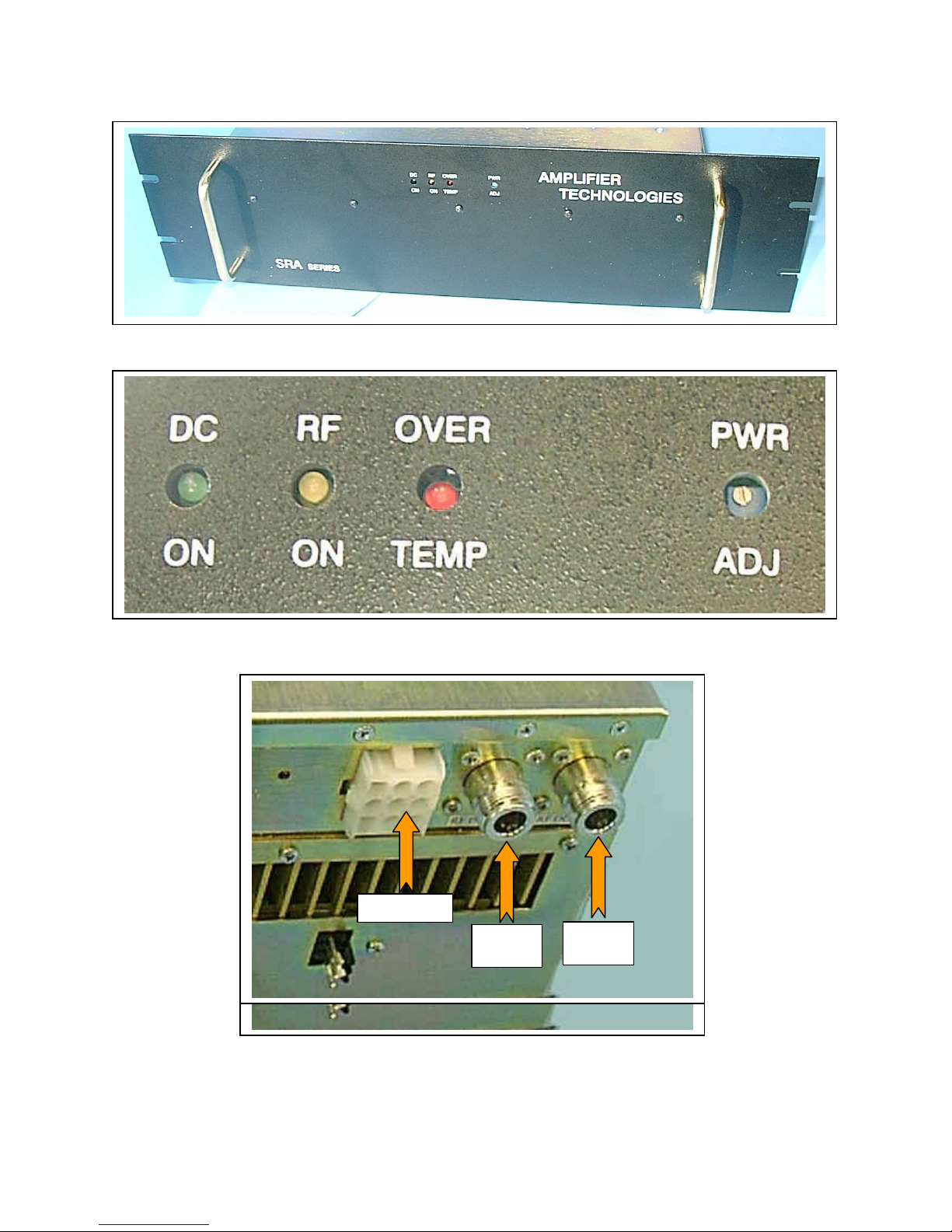
Figure 2 – Amplifier Technologies Inc 70W Power Amplifier
Figure 3 - Indicators and Power Adjustment Control
Figure 4 – Power Amplifier’s DC Power and RF Connectors
120 20191-100a Paragon-III User Manual
DC Power
DC Power
RF
Input
RF
Input
RF
Output
RF
Output
6
 Loading...