

Dataradio Integra-TR Technical Manual

Integra-TR
Technical Manual
Version 0.02
PRELIMINARY
The entire contents of this manual and the Software described
in this manual are copyright 1999 by Dataradio Inc.
Copyright D
February 1999
Part no.: 120 40101-002
ATARADIO
Inc.

Table of Contents
1. PRODUCT OVERVIEW................................................................................................................................... 1
NTENDED AUDIENCE
1.1 I
ENERAL DESCRIPTION
1.2 G
....................................................................................................................................... 1
.................................................................................................................................... 1
1.2.1 Characteristics........................................................................................................................................ 1
1.2.2 Accessories and options..........................................................................................................................1
ONFIGURATION
1.3 C
ACTORY TECHNICAL SUPPORT
1.4 F
RODUCT WARRANTY
1.5 P
EPLACEMENT PARTS
1.6 R
............................................................................................................................................... 1
........................................................................................................................2
...................................................................................................................................... 2
....................................................................................................................................... 2
1.6.1 Factory Repair........................................................................................................................................ 2
HYSICAL DESCRIPTION
1.7 P
1.8 D
IAGNOSTICS
.................................................................................................................................................... 2
.................................................................................................................................... 2
1.8.1 Remote Commands.................................................................................................................................. 3
IRMWARE UPGRADES
1.9 F
1.10 N
ETWORK APPLICATION
...................................................................................................................................... 3
............................................................................................................................... 3
1.10.1 RF Path and Communications Range.................................................................................................3
1.10.2 Basic Connections .............................................................................................................................. 3
1.10.3 Common Characteristics ...................................................................................................................3
1.10.4 Point to Point System.................................................................................................... ...................... 3
1.10.5 Point–Multipoint System..................................................................................................................... 4
1.10.6 Extending a Landline (Tail Circuit).................................................................................................... 4
2. FEATURES AND OPERATION......................................................................................................................5
VERVIEW
2.1 O
NTENDED AUDIENCE
2.2 I
RONT PANEL
2.3 F
........................................................................................................................................................ 5
....................................................................................................................................... 5
................................................................................................................................................... 5
2.3.1 Antenna Connector ................................................................................................................................. 5
2.3.2 LED Indicators........................................................................................................................................ 5
2.3.3 Connection to DTE.................................................................................................................................. 5
2.3.4 Com Port.................................................................................................................................................6
2.3.5 Setup Port................................................................................................................................................ 6
EAR PANEL
2.4 R
..................................................................................................................................................... 7
2.4.1 Heat Sink.................................................................................................................................................7
2.4.2 Power / Analog connector....................................................................................................................... 7
PERATION
2.5 O
....................................................................................................................................................... 7
2.5.1 Operating Modes..................................................................................................................................... 8
2.5.2 Data Forwarding Timer..........................................................................................................................8
2.5.3 Sending Break Signals ............................................................................................................................ 8
2.5.4 COM Port Baud Rates ............................................................................................................................ 8
2.5.5 Diagnostics..............................................................................................................................................8
2.5.6 Addressing............................................................................................................................................... 9
2.5.7 Station Type............................................................................................................................................. 9
NLINE DIAGNOSTICS
2.6 O
....................................................................................................................................... 9
2.6.1 Using an External Program for Online Diagnostics............................................................................... 9
2.6.2 Interpreting Diagnostic Results............................................................................................................ 10
FFLINE DIAGNOSTICS
2.7 O
OW POWER OPERATION
2.8 L
....................................................................................................................................12
................................................................................................................................13
2.8.1 Reduced Transmit Power...................................................................................................................... 13
2.8.2 Suspend Mode....................................................................................................................................... 13
i

2.8.3 Sleep Mode............................................................................................................................................13
2.8.4 Remote Unit Wake-up by DTE.............................................................................................................. 13
RANSMITTER TIMEOUT
2.9 T
2.10 O
PTIMIZING YOUR SYSTEM
.................................................................................................................................13
........................................................................................................................14
3. MAINTENANCE ADJUSTMENTS............................................................................................................... 15
VERVIEW AND MAINTENANC E INTERVALS
3.1 O
NTENDED AUDIENCE
3.2 I
QUIPMENT REQUIRED
3.3 E
EST POINT
3.4 T
ASIC ADJUSTMENTS
3.5 B
.....................................................................................................................................15
...................................................................................................................................15
.....................................................................................................................................................15
......................................................................................................................................15
...................................................................................................15
3.5.1 Preliminary Steps..................................................................................................................................15
3.5.2 After Adjustments are Done.................................................................................................................. 15
4. CIRCUIT DESCRIPTION..............................................................................................................................17
VERVIEW
4.1 O
NTENDED AUDIENCE
4.2 I
IRCUIT DESCRIPTION
4.3 C
......................................................................................................................................................17
.....................................................................................................................................17
....................................................................................................................................17
4.3.1 Microprocessor Circuit.........................................................................................................................17
4.3.2 RS232.................................................................................................................................................... 17
4.3.3 MODEM................................................................................................................................................ 17
4.3.4 TRANSMIT & RECEIVE DATA............................................................................................................17
4.3.5 Integra-T A/D and DIGIPOT................................................................................................................18
4.3.6 Wake-Up Circuit................................................................................................................................... 18
4.3.7 Power Supply ........................................................................................................................................18
ABLE
T
ABLE
T
ABLE
T
ABLE
T
ABLE
T
IGURE
F
IGURE
F
IGURE
F
IGURE
F
IGURE
F
IGURE
F
IGURE
F
IGURE
F
IGURE
F
IGURE
F
IGURE
F
IGURE
F
NTEGRA
1 I
2: COM
ETUP PORT SIGNALS
3: S
4: SWR / R
ESTS AND ADJUSTMENTS HALF AND FULL CHANNEL UNITS
5: T
ASIC CONNECTIONS REQUIRED
1 - B
OINT TO POINT SYSTEM
2 - P
OINT–MULTIPOINT SYSTEM
3 - P
AIL CIRCUIT
4 - T
5 - DCE C
NTEGRA
6 – I
7 – COM
WIRE INTERFACE
8 – 3-
NTEGRA
9 – I
OWER
10 - P
OWER
11- P
OGIC BOARD BLOCK DIAGRAM
12 - L
CCESSORIES AND OPTIONS
-T A
PORT SIGNALS
....................................................................................................................................... 6
..........................................................................................................1
..................................................................................................................................... 6
EV PWR
..........................................................................................................................................12
...................................................................................................................3
..............................................................................................................................4
.......................................................................................................................4
............................................................................................................................................... 4
ROSSOVER CABLE FOR
FRONT PANEL
-T
AND SETUP PORT CONNECTORS PIN LOCATIONS
RTS-CTS
............................................................................................................................5
MODE
...................................................................................................................................... 6
REAR PANEL
-T
NALOG CONNECTOR
/ A
NALOG CABLE
/ A
..............................................................................................................................7
..................................................................................................................7
............................................................................................................................7
..............................................................................................................19
.............................................................................16
...........................................................................................4
................................................................................6
ii

What's New in this Version
Document various corrections
History
0.01: This version 0.01 of the first preliminary version of the Integra-TR technical manual will be replacing the Integra-T manual versions. The Integra-TR is compliant to the FCC refarming (19.2Kb/s in
25KHz channels and 9.6KHz in 12.5KHz channels).
iii

Definitions
The following terms are used throughout this document.
Bit dribble
COM Port
CTS
DCE
DOX
DTE
Network speed
PLC
RDS
RRSS
RSS
RTS
RTS mode
RTU
SCADA
SETUP Port
Transparent
Extraneous bits delivered at the end of a data transmission. Equivalent to a
“squelch tail” in voice systems. Integra-T does not have bit dribble.
The Communications Port of Integra-T. This port is configured as DCE and is
designed to connect directly to DTE.
Clear to Send. An RS-232 output signal from Integra-T indicating that it is ready
to accept data.
Data Communications Equipment. This designation is applied to equipment such
as modems. DCE is designed to connect to DTE.
Data Operated Transmit. A mode of operation in which Integra-T begins a
transmission as soon as data is presented to the RS-232 port.
Data Terminal Equipment. This designation is applied to equipment such as terminals, PCs, RTUs, PLCs, etc. DTE is designed to connect to DCE.
This is the
port
baud rate.
Programmable Logic Controller. An intelligent device that can make decisions,
gather and report information, and control other devices.
Radio Diagnostic Software. This software allows local and remote diagnostics of
Integra-T.
Remote Radio Setup Software. (Future expansion software package)
Radio Service Software. This software allows configuration and testing of Inte-
gra-T.
Request to Send. RS-232 input signal to Integra-T indicating that the DTE has
data to send. RTS may optionally be used as a transmit switch for Integra-T.
A mode of operation in which Integra-T begins a transmission when RTS is
raised, and continues transmitting until RTS is dropped.
Remote Terminal Unit. A SCADA device used to gat her information or control
other devices.
Supervisory Control And Data Acquisition. A general term referring to systems
that gather data and/or perform control operations.
The configuration / diagnostic port of Integra-T. This port is designed to be con-
nected to a PC running the Integra RSS program.
A transparent unit transmits all data without regard to special characters, etc.
bit rate
on the RF link between units. Could be different from COM
iv

1. PRODUCT OVERVIEW
This document provides the information required for the installation, operation and maintenance of the Dataradio Integra-TR radiomodem.
1.1 Intended Audience
This manual is intended for use by system designers, installers and maintenance technicians
1.2 General Description
Integra-TR is a high-speed transparent radiomodem, FCC refarmed compliant, designed
specifically to fit the needs of SCADA,
telemetry and control applications. Integra-TR
provides the communication links among data
equipment for installations where wired communication is impractical.
Integra-TR will work with most makes and
models of RTU, PLC and with their protocols
(usually polling). Configuration settings allow
tailoring for a variety of applications.
Integra-T supports:
• Fully transparent operation with error-free
data delivery.
• Allows transmission of “break” characters.
• DOX (Data Operated Transmit) or RTS
mode.
• Stations may be set as “master” or “remote”
to prevent remote stations from hearing each
other.
• Full local and remote diagnostics
• Two 8-bit analog inputs (0 - 10V).
• Low power consumption modes: “sleep”
and “suspend” modes (nominal 7mA).
• “12 VDC, negative ground”, device.
1.2.2 Accessories and options
Table 1 Integra-T Accessories and options
Accessory DR Part #
Local RSS & RDS software kit
(diskette and setup/data cable)
Technical manual 120 40101-xxx
SMA Male – BNC Female
adapter
085 03281-0xx
685 00832 –000
1. Point to point Master–Slave or Peer to Peer
configurations in simplex or half-duplex
modes.
2. Point to multipoint Master–Slave configuration in simplex or half-duplex modes.
Settings and connections for these configurations are given later in this manual.
1.2.1 Characteristics
Integra-TR has the following characteristics:
• Selectable network speeds of 4800, 9600 for
half channel units and 4800, 9600 and
19.200 b/s for full channel units.
• Backward compatible with the Integra-T for
bit rate of 4800 and 9600 b/s (full channel
units only)
• One COM port for connection to DTE.
Speeds 300 - 19200 bauds.
• One Setup port, for configuration and
diagnostics.
• Built-in 5-watt transceiver, operating in the
VHF, UHF or 900 MHz communications
bands. Half-duplex or simplex operation.
Cooling fan – factory option
(for high duty-cycle transmit
applications)
For continuous-transmit applications, the “TX
Catalog number /F
suffix.
Timeout” timer must be turned off (set to “disable”) via the Radio Service Software (RSS).
1.3 Configuration
Operating characteristics of Integra-TR are configured by means of Integra-TR’s
Software
(RSS) available from your sales repre-
sentative. Also available is Integra-T’s
Diagnostic Software
(RDS) which permits both
local and remote diagnostics.
Service Software (RRSS
) to allow remote programming is a future expansion. The RSS, RDS
and RRSS (future option) programs are MSDOS
based and will run on any 486 or higher PC (2
Megabytes memory required).
Integra-TR requires the use of the RSS for
both configuration and adjustment.
Radio Service
Radio
Remote Radio
120 40101-103
1
Integra T Technical Manual

1.4 Factory Technical Support
The Technical Support departments of Dataradio and Johnson Data Telemetry (JDT) provide
customer assistance on technical problems and
serve as an interface with factory repair facilities. Technical support hours are respectively:
for Dataradio, 9:00 AM to 5:00 PM, Eastern
Time, Monday to Friday and for JDT, 7:30 AM
to 4:30PM, Central Time, Monday to Friday.
Technical support can be reached in the following ways:
For equipment purchased from Dataradio:
Dataradio Inc.
5500 Royalmount Ave, suite 200
Town of Mount Royal
Quebec, Canada H4P 1H7
phone: +1 514 737-0020
fax: +1 514 737-7883
Contact Technical Support for service information before returning equipment. A Technical
Support representative may suggest a solution
eliminating the need to return equipment.
1.6.1 Factory Repair
When returning equipment for repair, you must
request an RMA (returned merchandise authorization) number. The Tech Support representative will ask you several questions to clearly
identify the problem. Please give the representative the name of a contact person, who is familiar with the problem, in case questions arise
during servicing of the unit.
Customers are responsible for shipping charges
for returned units. Units in warranty will be repaired free of charge unless there is evidence of
abuse or damage beyond the terms of the warranty. Units out of warranty will be subject to
service charges. Information about these charges
is available from Technical Support.
Email address: support@dataradio.com
For equipment purchased from JDT:
Johnson Data Telemetry Corp.
Customer Service Department
299 Johnson Avenue, P.O. Box 1733
Waseca, MN 56093-0833
phone:1-800-992-7774 and
+1-507 835-6408
fax: +1-507-835-6648
Email address: support@johnsondata.com
1.5 Product Warranty
Warranty information may be obtained by contacting your sales representative.
1.6 Replacement Parts
This product is normally not field-serviceable,
except by the replacement of complete units.
Specialized equipment and training is required
to repair logic boards and radio modules.
1.7 Physical Description
Integra-TR consists of a logic PCB (which includes the modem circuitry) and a separate radio
module. The two boards plug directly together
and slide into the rails of an extruded aluminum
case. DTE connection is made via a front panel
connector. Power is applied through a connector, which also includes analog inputs, on the
rear panel. The unit is not hermetically sealed
and should be mounted in a suitable enclosure
where dust and/or a corrosive atmosphere are
anticipated. There are no external switches or
adjustments; operating parameters are set using
the RSS.
1.8 Diagnostics
Integra-TR has sophisticated built-in diagnostics
that may be transmitted automatically without
interfering with normal network operation. In
addition, commands to generate test transmissions, etc., may be issued either locally or remotely.
Diagnostic information takes one of two forms:
120 40101-103
2
Integra T Technical Manual
Online diagnostics. Information is auto-
matically sent by each unit at the beginning
of every data transmission.
Offline diagnostics. Information is sent by a
specific unit in response to an inquiry made
locally or from another station.
Diagnostics are processed using the Integra-TR’
RDS.
1.8.1 Remote Commands
The upcoming Integra RRSS will allow configuring most functions and adjustments remotely
via the radio network.
Sending remote commands and receiving responses is done with the host application offline.
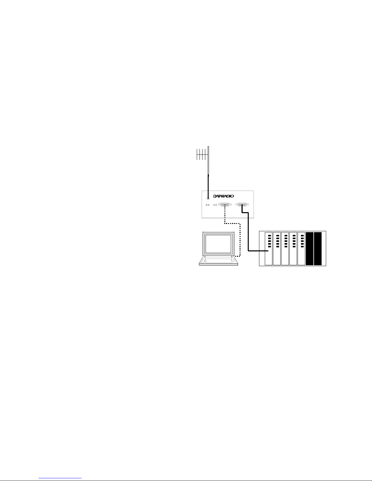
1.10.2 Basic Connections
The connections required (except power) are
shown below in Figure 1.
While an RTU or PLC is shown in the diagram,
master stations often use a PC running an application designed to communicate with remote
RTUs or PLCs.
The Setup PC is used for both configuration and
local and remote diagnostics. It may be left connected at all times if desired, but is not required
for normal operation once the unit has been configured.
Antenna
1.9 Firmware Upgrades
Integra-TR’s firmware resides in flash EPROM
and is designed to allow field upgrades.
Upgrades are done using a PC connected to Integra-TR and do not require that the unit be
opened.
1.10 Network Application
Integra-TR is suited to a variety of network applications. Its primary design goal was to satisfy
the needs of SCADA systems using RTUs or
PLCs in either point to point or point–multipoint
service.
This section gives an overview of some common
configurations. Selection of “master” or “remote” as well as data delivery conditions is
done using the Integra RSS.
1.10.1 RF Path and Communications
Range
Integra-TR is designed for use over distances up
to 30 miles (50 km) depending on terrain and
antenna system. To assure reliable communications, the RF (radio frequency) path between
stations should be studied by a competent professional, who will then determine what antennas are required, and whether or not a repeater is
needed.
Integra
®
Integra
Setup PC
Figure 1 - Basic connections required
RTU or PLC
1.10.3 Common Characteristics
The networks described below share a number
of common characteristics.
1. The network speed (4800 or 9600 b/s) must
be the same for all stations in a network.
2. Unless otherwise noted, the default setting
of station type is “master” and data delivery
is “all”.
3. Transmission of online diagnostics may be
enabled or disabled at any station or stations
without affecting their ability to communicate with other stations.
1.10.4 Point to Point System
A simple point to point connection is shown
below:
120 40101-103
3
Integra T Technical Manual
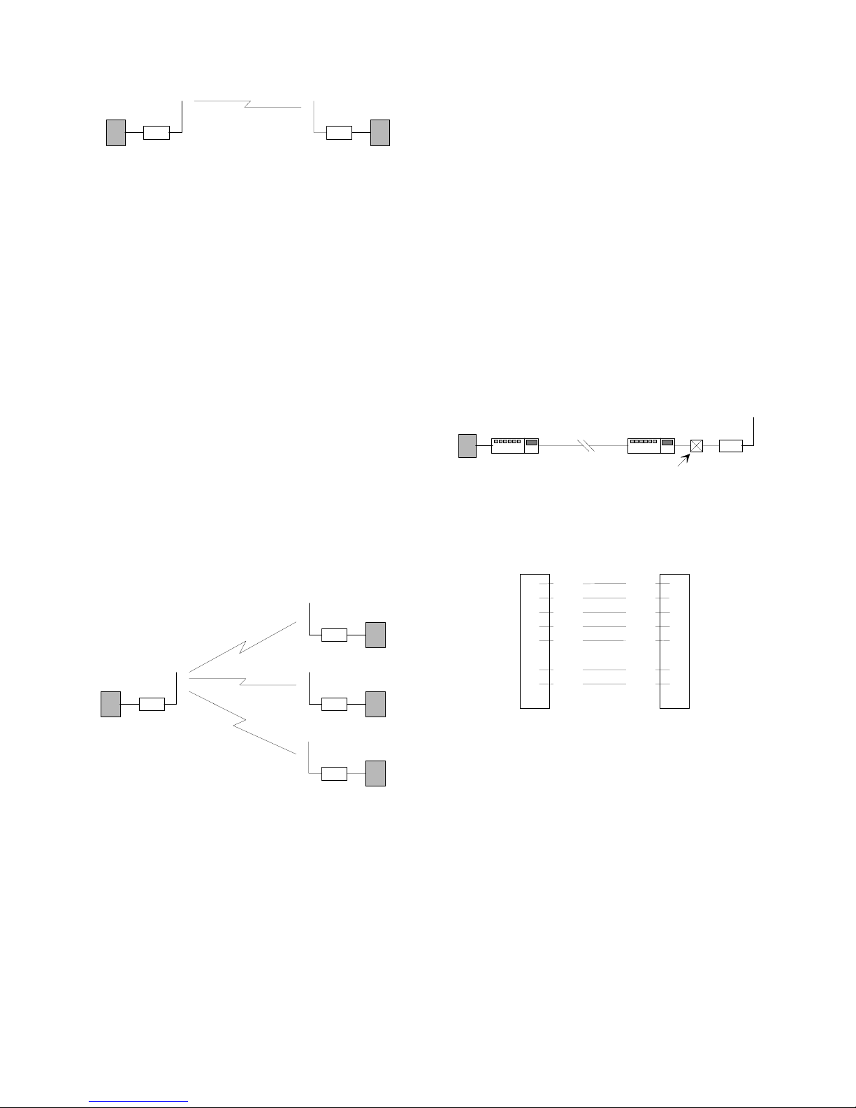
Integra
DTE
Figure 2 - Point to Point System
In such a system, the user’s equipment (DTE)
Integra
DTE
may be set up in either a peer-to-peer or a master slave configuration. The Integra-T’s may be
left in their default configuration, which is:
1. Both units set as “master”.
2. Both units set to deliver “all” data transmissions.
Two other configurations that would work
equally well are:
1. One unit set to “master”, the other to “remote”, delivery set to either “all” or “selective” data transmissions.
2. Both units set to “remote”, data delivery set
to “all”.
If a simplex radio network is used (i.e. a single
frequency for all stations) we recommend that
the master Integra-TR be set to “master”, the
remotes to “remote” and all units to “selective”
data delivery. This will prevent remote stations
from hearing each other’s responses. Use this
setting also if a full duplex repeater is used.
1.10.6 Extending a Landline (Tail
Circuit)
Integra-TR may be used to extend a landline
circuit (giving access to difficult locations, etc.).
This type of connection is called a “tail circuit”
and is shown in Figure 4 below. The tail circuit
assembly may be used in any of the network
types described in the preceding sections.
DTE
Figure 4 - Tail Circuit
line
modem
dedicated
line
DCE crossover
modem
cable
line
Integra T
1.10.5 Point–Multipoint System
A basic point–multipoint system is shown
below:
remote
master
Figure 3 - Point–Multipoint System
If a half-duplex radio network is used (i.e. two
frequencies with the master station transmitting
and receiving on the reverse pair from the remotes) the Integra-TR’s may be left in their default configuration (station type “master” and
data delivery “all”). The master station can be
either full duplex or half-duplex.
remote
remote
Note: The line modems should be full duplex
units.
DCD
RXD
TXD
DTR
GND
RTS
CTS
DE-9M
1
2
3
4
5
6
7
8
9
DE-9M
RTS
7
TXD
3
RXD
2
CTS
8
GND
5
DCD
1
DTR
4
Figure 5 - DCE Crossover Cable for RTS-CTS mode
However, some point-to-point FDX landline
modems or line drivers may require the use of
DOX mode and an
alternate pinout
for
two
of
the above lines.
All other lines remain as shown in Figure 5
above.
8
CTS
1 DCD
RTS 7
DTR 4
120 40101-103
4
Integra T Technical Manual
 Loading...