

Dataradio INTEGRA-H Technical Manual
INTEGRA
H Version
Technical Manual
INTEGRA-H
Copyright 2000 by DATARADIO COR Ltd.
Part Number: 001-4090-101/102
Revision 0
September 2000
DATARADIO COR Ltd. designs and manufactures radios and radio modems to serve a wide variety of data communication
needs. DATARADIO produces equipment for the fixed data market including SCADA systems for utilities, petrochemical,
waste and fresh water management markets and RF boards for OEM applications in the Radio Frequency Data Capture
market.
PRODUCT WARRANTY
The manufacturer's warranty statement for this product is available from DATARADIO COR, Ltd. 299 Johnson Avenue,
Box 1733, Waseca, MN 56093-0833. Phone (507) 835-8819.
The information in this document is subject to change without notice.
is a trademark of DATARADIO, Inc.

SECTION 1
PRODUCT OVERVIEW
1.1 SCOPE OF MANUAL
This document provides information required for the operation and preventive maintenance of the
DATARADIO COR Ltd. Integra-H Spread Spectrum Radiomodem. This manual is intended for system designers,
professional installers and maintenance technicians
1.2 GENERAL DESCRIPTION
Integra-H is a high-speed protocol transparent radiomodem. It is designed specifically to fit the needs of
Supervisory Control and Data Acquisition (SCADA), telemetry and control applications. Integra-H provides the
communication links to data equipment for installations where wired communication is impractical.
Integra-H will work with most makes and models of remote terminal units (RTU) and programmable logic
controllers (PLC) and their protocols. Configuration settings allow tailoring for a variety of application
requirements.
Integra-H supports:
1. Point to point configuration in switched simplex mode
2. Point to multipoint configuration
Settings and connections for these configurations are given later in this manual
1.2.1 CHARACTERISTICS
Integra-H has the following characteristics:
l Selectable network speeds of 9600, 19200, 21400, and 25600 b/s
l One COM port for connection to DTE. Speed of 300 - 19200 baud
l One Setup port, for configuration and diagnostics output (speed fixed to 9600 baud, 8 bit, (unlicensed
frequency hopping band) no parity, 1 stop bit
l Built-in 0.1 - 1-watt transceiver, operating in the 902-928 MHz communications bands
l Fully transparent operation with error-free data delivery (no “dribble bits”)
l Allows transmission of “break” characters
l DOX (Data Operated Transmit) or RTS mode
l Two 8-bit analog inputs (0 - 10V)
l Low power consumption modes: “sleep” and “suspend” modes (< 20 mA)
l “13.3 VDC, negative ground” device
001-4090-101/102
1-1

PRODUCT OVERVIEW
1.2.2 ACCESSORIES AND OPTIONS
Table 1-1 Integra-H Accessories and Options
Accessory DRL Part Number
Local RSS & RDS software kit (diskette and setup/data cable) 023-4090-005
SMA Male - BNC Female adapter cable 023-3410-098
Power cable 732-03273-001 (DRI p/n)
For information on accessories and options, contact your sales representative. In the United States phone
1-800-992-774. For international sales, phone 1-612-882-5529 or 1-305-829-4030.
1.2.3 CONFIGURATION
Operating characteristics of the Integra-H are configured by means of Integra-H Radio Service Software
(INTRSS). The RSS/RDS software kit also includes the Radio Diagnostic Software (INTDIAG), which permits
both local and remote diagnostics. These programs are Win/95 or later based (16 Megabytes of memory required).
Integra-H requires the use of INTRSS for both configuration and adjustment.
1.3 FACTORY TECHNICAL SERVICE
The Technical Service Department provides customer assistance on technical problems and serves as an
interface with factory repair facilities. They can be reached in the following ways:
Dataradio COR Ltd.
299 Johnson Avenue, P.O. Box 1733
Waseca, MN 56093-0833
Technical Service hours are: Monday to Friday 7:30 AM to 4:30 PM, Central Time
Phone: 1-800-992-7774
1-507-835-6408 or 1-507-835-8819
Fax:1-507-835-6648
Email address: support@dataradio-cor.com
1.4 PRODUCT WARRANTY
The warranty statement for the Integra-H is available by contacting your sales representative. DRL
warranties are included in .pdf format on CD versions of DATARADIO technical manuals.
Part No. 001-4090-101/102
1-2

PRODUCT OVERVIEW
1.5 REPLACEMENT PARTS
This product is normally not field-serviceable, except by the replacement of complete units. Specialized
equipment and training is required to repair logic boards and radio modules.
Contact Technical Service for information before returning equipment. A Technical Service
representative may suggest a solution eliminating the need to return equipment.
1.6 FACTORY REPAIR
Dataradio products are designed for long life and failure-free operation. If a problem arises, factory
service is available. Contact the Technical Service Department before returning equipment. A service
representative may suggest a solution eliminating the need to return equipment.
A Return Material Authorization (RMA) is required when returning equipment to Dataradio for repair.
Contact the Technical Service Department at 800-992-7774, extension 6290 to request an RMA number. Be
prepared to give the equipment model and serial number, your account number (if known), and billing and
shipping addresses.
Include the RMA number, a complete description of the problem, and the name and phone number of a
contact person with the returned units. This information is important. The technician may have questions that need
to be answered to identify the problem and repair the equipment. The RMA number helps locate your equipment
in the repair lab if there is a need to contact Dataradio concerning the equipment. Units sent in for repair will be
returned to the customer re-tuned to the current Dataradio Test and Tune Procedure and will conform to all
specifications noted in this section
Customers are responsible for shipping charges (to Dataradio) for returned units in warranty. Units in
warranty are repaired free of charge unless there is evidence of abuse or damage beyond the terms of the warranty.
Dataradio covers return shipping costs for equipment repaired while under warranty.
Units out of warranty are subject to repair service charges. Customers are responsible for shipping charges
(to and from Dataradio) on units out of warranty. Return shipping instructions are the responsibility of the
customer.
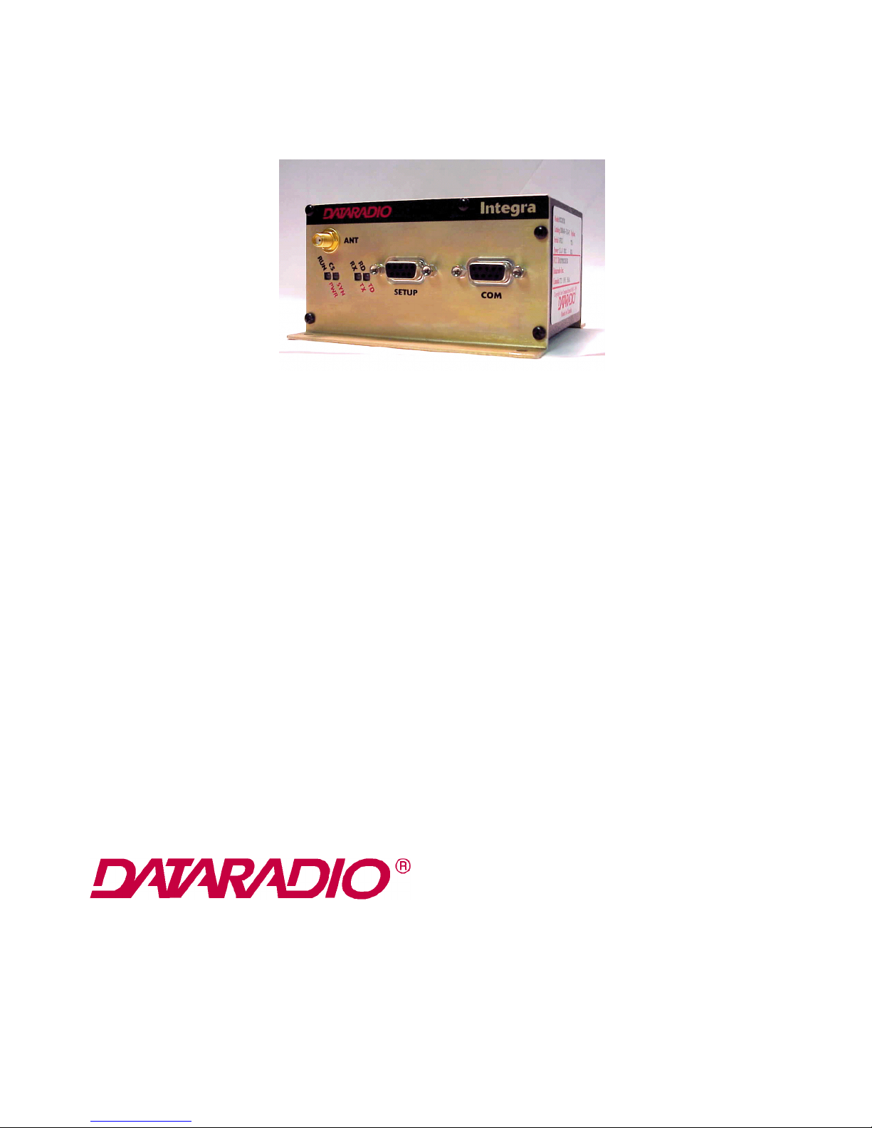
1.7 PHYSICAL DESCRIPTION
Integra-H consists of a logic PCB (which includes modem circuitry) and a radio module. Each logic PCB
and radio module are matched together and characterized in the factory to optimize performance as an intelligent
unit. The two boards then slide into the rails of an extruded aluminum case.
The Integra-H transceiver “hops” from channel to channel several times per second using a “hop” pattern
applied to the master and remotes in a network. A distinct hopping pattern is provided for each of the available
network addresses. This distinct pattern minimizes the chance of interference with other spread spectrum
networks. In the United States (and certain other countries), no license is necessary to install and operate this type
of spread spectrum system.
DTE connection is made via a front panel connector. Power is applied through a rear panel 4-pin
connector which includes two programmable analog connections usable as inputs or specialized outputs.
Part No. 001-4090-101/102
1-3

PRODUCT OVERVIEW
The unit is not hermetically sealed and should be mounted in a suitable enclosure when dust and/or a
corrosive atmosphere are anticipated. Physically, there are no external switches or adjustments. All operating
parameters are set using the INTRSS software program.
1.8 DIAGNOSTICS
Integra-H has sophisticated built-in diagnostics that may be transmitted automatically without interfering
with normal network operation. In addition, commands to generate test transmissions, etc., may be issued either
locally or remotely.
Diagnostic information takes one of two forms:
Online diagnostics Information is automatically sent by each unit at the beginning of every data
transmission. Online diagnostics are available via the setup port or INTDIAG software.
Offline diagnostics Information is sent by a specific unit in response to an inquiry made locally or from
another station. Off
1.9 FIRMWARE UPGRADES
The Integra-H firmware resides in flash EPROM and is designed to allow field upgrades.
Upgrades are done using a PC connected to the Integra-H but do not require opening the unit. Upgrades
require interaction with DRL’s Technical Service.
1.10 INSTALLATION
1.10.1 PROFESSIONAL INSTALLATION REQUIRED
The Integra-H complies with Part 15 of the FCC rules and must be professionally installed. Operation
must conform to the following conditions
lThis device may not cause interference
lThis device must accept any interference including interference that may cause undesired operation of
the device
The installer of this equipment must ensure the antenna is located or pointed such that it does not emit
RF field in excess of Health Canada limits for the general population; consult Safety Code 6 (available from
Health Canada).
1.10.2 ANTENNA CONNECTION
This equipment has been tested and approved with antennae having a maximum gain of 10 dB. Antennae
with a higher gain are strictly prohibited (regulations of Industry Canada). The required antenna impedance is 50
ohms. To reduce potential radio interference, the antenna type and its gain should be chosen to ensure the
equivalent isotropically radiated power (EIRP) is not more than required for successful communication.
Part No. 001-4090-101/102
1-4
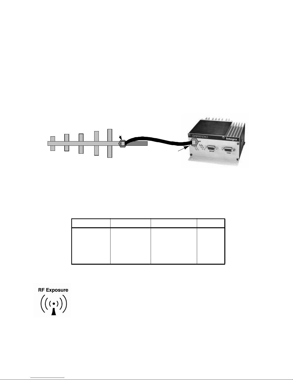
FCC/IC Rule: The output power is not to exceed 1.0 watt and the EIRP not to exceed 6 dBW if the hopset
uses 50 or more frequencies. A sample calculation is provided below.
Sample Calculation: Yagi Antenna: 10 dB Exceeds 6 dBi gain by 4 dB
Cable Loss: 1 dB
Integra-H output must be reduced by 4 dB (plus 1 dB to account for cable loss)
30 dBm - 4 dB + 1 dB (cable loss) = 27 dBm at antenna port of Integra-H
after 1 dB loss through cable: 27 dBm - 1 dB = 26 dBm input to antenna
Result: reduction of 4 dB
10 dBm gain Yagi
ERIP = 36 dBm
26 dBm
27 dBm
PRODUCT OVERVIEW
1.10.3 ACCEPTABLE ANTENNAE
The antennae listed in Table 1-2 were tested and typed for maximum gain. These antennae are FCC
approved for use with the Integra-H.
Type Manufacturer Part Number Gain (dBi)
Yagi Maxrad MYG9159 10
Omni Directional Maxrad MFB9157 7
Unity Gain Maxrad MFB9150 0
Whip Maxrad EXE-902-SM or
1.10.4 SAFETY NOTICE
The Integra-H uses low power radio frequency transmitters. The concentrated
energy from an antenna may pose a health hazard. People should not be in front of
the antenna when the transmitter is operating.
Figure 1-1 Sample Equation Graphic
Table 1-2 Acceptable Antennae
0
EXR-902-BN
Part No. 001-4090-101/102
1-5
PRODUCT OVERVIEW
1.11 NETWORK APPLICATION
Integra-H is suited to a variety of network applications. Its primary design goal satisfies the needs of
SCADA systems using RTUs, PLCs, or other similar equipment in either point-to-point or point-to-multipoint
service.
This section gives an overview of some common configurations. Selection of “master” or “remote” as
well as data delivery conditions is done using INTRSS.
1.11.1 RF PATH AND COMMUNICATIONS RANGE
Integra-H is designed for use over distances dependent on terrain and antenna system. To assure reliable
communications, the RF (radio frequency) path between stations should be studied by a competent professional
who can determine what antennae are required and whether or not a repeater is needed.
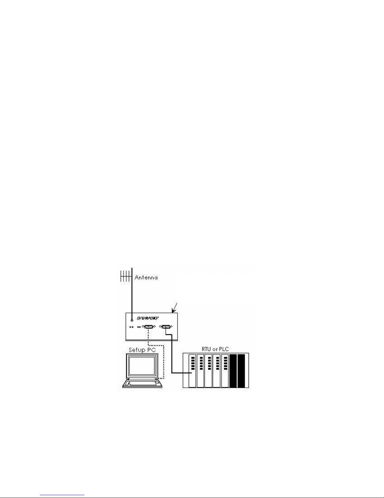
1.11.2 BASIC CONNECTIONS
The connections required are shown in Figure 1-2.
While an RTU or PLC is shown in the diagram, master stations often use a PC running an application
designed to communicate with remote RTUs or PLCs.
The Setup PC is used for both configuration and local and remote diagnostics. It may be left connected at
all times but is not required for normal operation once the unit has been configured.
13.3VDC / 2A
Regulated power supply
connects on rear
Figure 1-2 Basic Required Connections
Part No. 001-4090-101/102
1-6

PRODUCT OVERVIEW
1.11.3 COMMON CHARACTERISTICS
The networks described in this section share common characteristics:
1.The network speed (9600, 19200, 21400, and 25600 b/s) must be the same for all stations in a network.
2.Transmission of online diagnostics may be enabled or disabled at any station or stations without
affecting their ability to communicate with other stations.
1.11.4 POINT-TO-POINT SYSTEM
A simple point-to-point connection is shown in Figure 1-3.
Figure 1-3 Point-to-Point System
In this system, the user's equipment (DTE) is set up in a master-remote configuration.
1.11.5 POINT-MULTIPOINT SYSTEM
Basic point-multipoint systems are shown in Figure 1-4:
remote
Master
(simplex or half-duplex)
Figure 1-4 Point-Multipoint System
Using the Integra-H programming software, one Integra-H must be set to “master”. The remaining units in
the network must be set to “remote”. All units are set to “selective” data delivery to prevent remote stations from
hearing each other's responses.
remote
remote
Part No. 001-4090-101/102
1-7
PRODUCT OVERVIEW
2
4
8
3
8
4
DCD
RTS
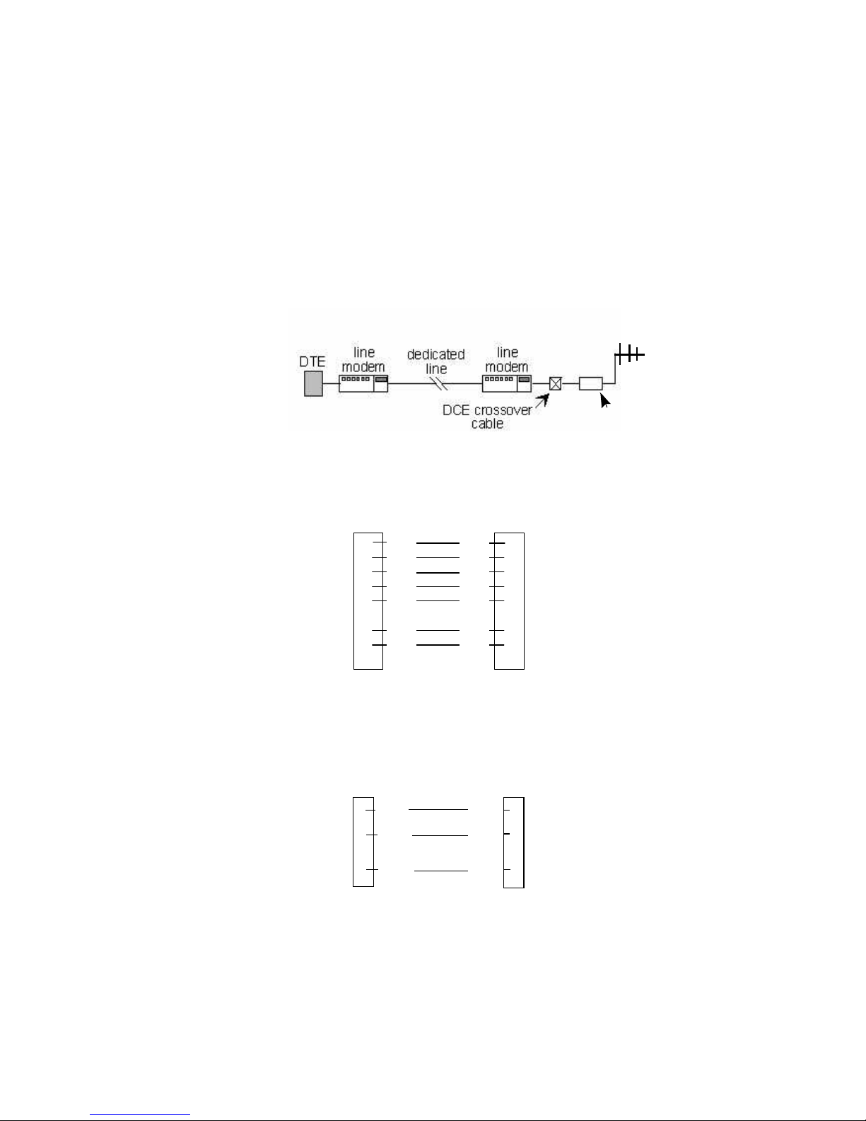
1.11.6 EXTENDING A LANDLINE (TAIL CIRCUIT)
Integra-H may be used to extend a landline circuit (giving access to difficult locations, etc.). This type of
connection is called a “tail circuit” and is shown in Figure 1-5. The tail circuit assembly may be used in any of the
network types described in the preceding sections.
Integra-H
Figure 1-5 Landline (Tail Circuit)
Note: The phone-line modems should be full duplex units.
DE-9M
7
2
5
1
TXD
RXD
CTS
GND
DCD
DTR
DE-9M
RXD
TXD
DTR
GND
RTS
CTS
Figure 1-6 DCE Crossover Cable for RTS-CTS mode
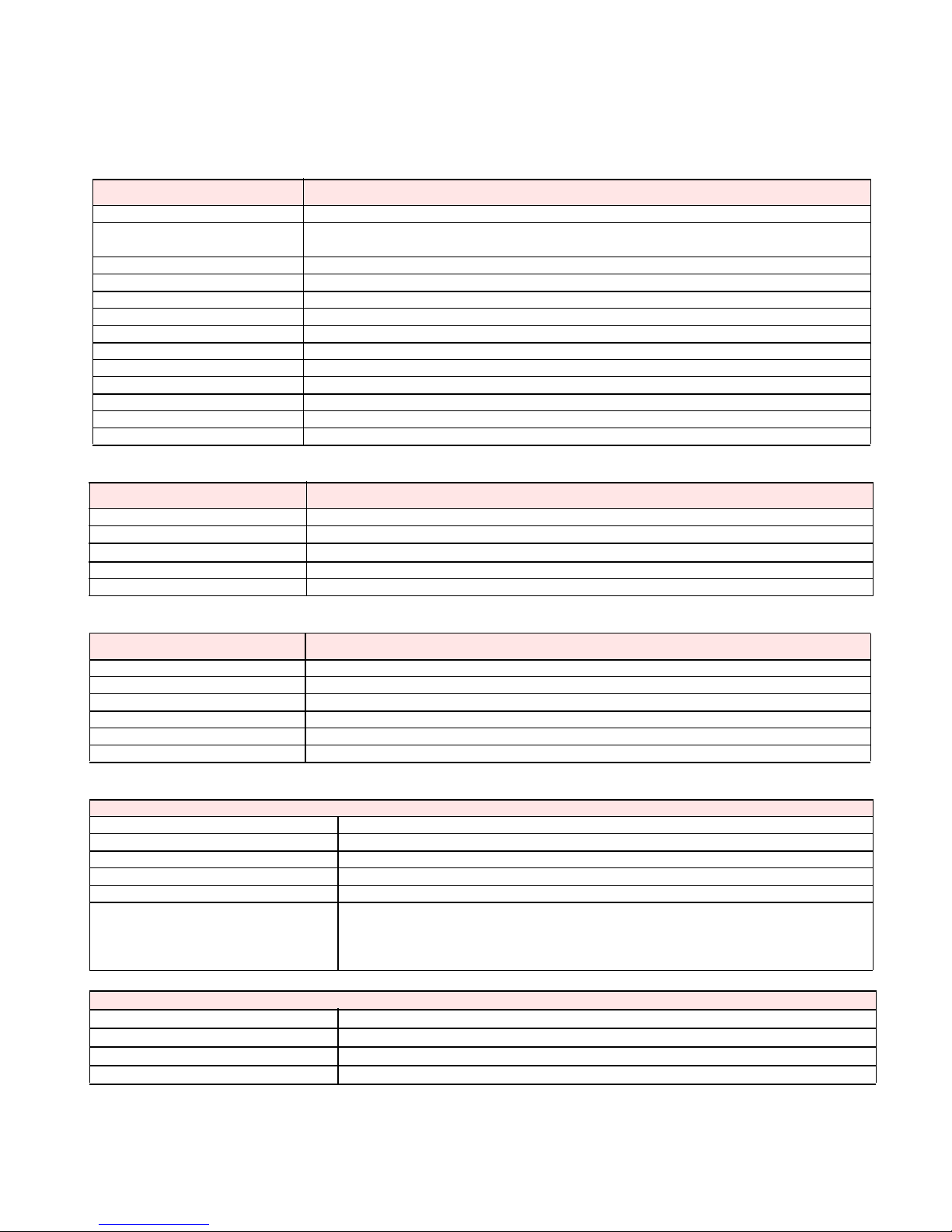
Some point-to-point FDX landline modems or line drivers may require the use of DOX mode and an
alternate pinout for DTR, DCD, CTS and RTS as shown in Figure 1-8.
TXD RXD
3
2
RXD TXD
5
GND GND
Figure 1-7 DCE Crossover Cable for DOX mode
1
3
5
6
7
9
2
3
5
Part No. 001-4090-101/102
1-8

Master
PRODUCT OVERVIEW
Remote
Integra-H
Master
Integra-H
Integra-H
RS-232 Serial
Store and Forward Device
Integra-H
RS-232 Serial
Figure 1-8 Point-Multipoint Using a Store and Forward Device
Hop Sequence 1
A
Integra-H
Hop Sequence 2
B
Integra-H
Remote
Integra-H
Remote
Integra-H
Remote
Integra-H
Remote
Integra-H
Remote
Integra-H
Part No. 001-4090-101/102
Integra-H
Data line harness (RS232 Serial)
Figure 1-9 Point-Multipoint (Repeater)
1-9
PRODUCT OVERVIEW
GENERAL SPECIFICATIONS
These specifications are subject to change without notice.
GENERAL
Frequency 902-928 MHz
Controlled Channel Access Interference avoidance system Carrier Sense or Active Channel monitoring for dynamic channel
usage
IF Channel Steps: 50 kHz for systems
IF Channel Bandwidth 30 kHz (Minimum 512 channels @ 900 MHz)
Operating Temperature -30° to + 60° C
Supply voltage 10 - 16 VDC maximum
Receive Current 200 ma
Transmit Current 650 ma
Standby Current 20 ma
Data Format Asynchronous 7 and 8 bit words
User Data Rates 19200, 21400, 25600 baud
Data Protocol Transparent to user data
Nominal Dimensions 4.5" W x 2.2" H x 4.75" D (11.4 x 5.6 x 12.1 cm)
RECEIVER
Sensitivity 10-6 BER @ -105 dBm @ 9600 bps
Intermodulation 75 dB
Spurious Rejection
Conducted Spurious 70
Secondary Image 65 dB
*psophometrically weighted
80
TRANSMITTER
RF Power Output .100 -1 Watt, software adjustable
Spurious and Harmonics
Frequency Stability 1.5 ppm
Output Impedance 50 ohms
Maximum SWR Stable over 10 to 1
Tx Duty Cycle 100% unlimited Tx time
Modem / Logic
Operation Switched Simplex
Data Bit Rates 25 kHz channel: 19200, 21400, 25600 baud
Modulation Type DRCMSK (Differential Raise-Cosine Minimum Shift Keying)
RTS/CTS Delay (RTS mode) 4 ms
Addressing 8 bit station address, 1 bit station type (master / remote)
Bit Error Rate (BER)
9600 b/s, 12.5 kHz
9600 and 4800 b/s, 25 kHz
19200 b/s, 25 kHz
1 x 10 -6 at 1.4 µV minimum /-104 dBm
1 x 10 -6 at 1.0 µV minimum / -107 dBm
1 x 10 -6 at 2.3 µV minimum / -100 dBm
COM Port
Interface EIA RS-232C
Data Rate 300 - 19200 b/s
Protocol Transparent, 7 or 8 data bits, 1 or 2 stop bits, even, odd or no parity
Transmit Control RTS or DOX (data operated transmit)
Part No. 001-4090-101/102
1-10

PRODUCT OVERVIEW
Setup/Diag Port
Data Format Proprietary binary for setup, ASCII for diagnostics
Data Rate 9600 b/s, 8 bit, no parity, 1 stop bit
Analog Inputs
Interface Two inputs, 0-10 VDC, 8 bits. May be read only via offline diagnostics.
Absolute maximum input voltage < 20 Vdc. Inputs are reverse-voltage protected.
Display
4 Bi-color status LEDs RUN/PWR/ CS/SYN, RX/TX, RD/TD
Connectors
RF SMA Female
COM DE-9F
SETUP/DIAG DE-9F
Power/Analog Snap & Lock 4-Pin DC Power Jack
Diagnostics
Online Short ID, temperature, B+ voltage, local RSSI, remote RSSI, fwd and rev power, Rx
Quality
Offline As for Online plus: Demodulated Signal Voltage, Analog Input Levels
Part No. 001-4090-101/102
1-11
 Loading...