

Dataradio DL-3282 Setup Instructions
DL-3282 MODEM
SETUP INSTRUCTIONS
INTERCONNECT CABLE INSTALLATION
This modem requires a power source with an operating
voltage range of 7 - 16 Vdc. Note: A transceiver may
require a more restrictive operating range.
Table 1 3282 INTERCONNECT CABLES
TRANSCEIVER
MODEL
3400 023-3410-125 10-Pin (2)*
RNet / JSLM 697-3282-012 DE-15 (1) & DA-15 (1)
*
See Figures 4 and 5 for pinout details.
DRL CABLE # CONNECTOR TYPES
(to spade terminals)
*
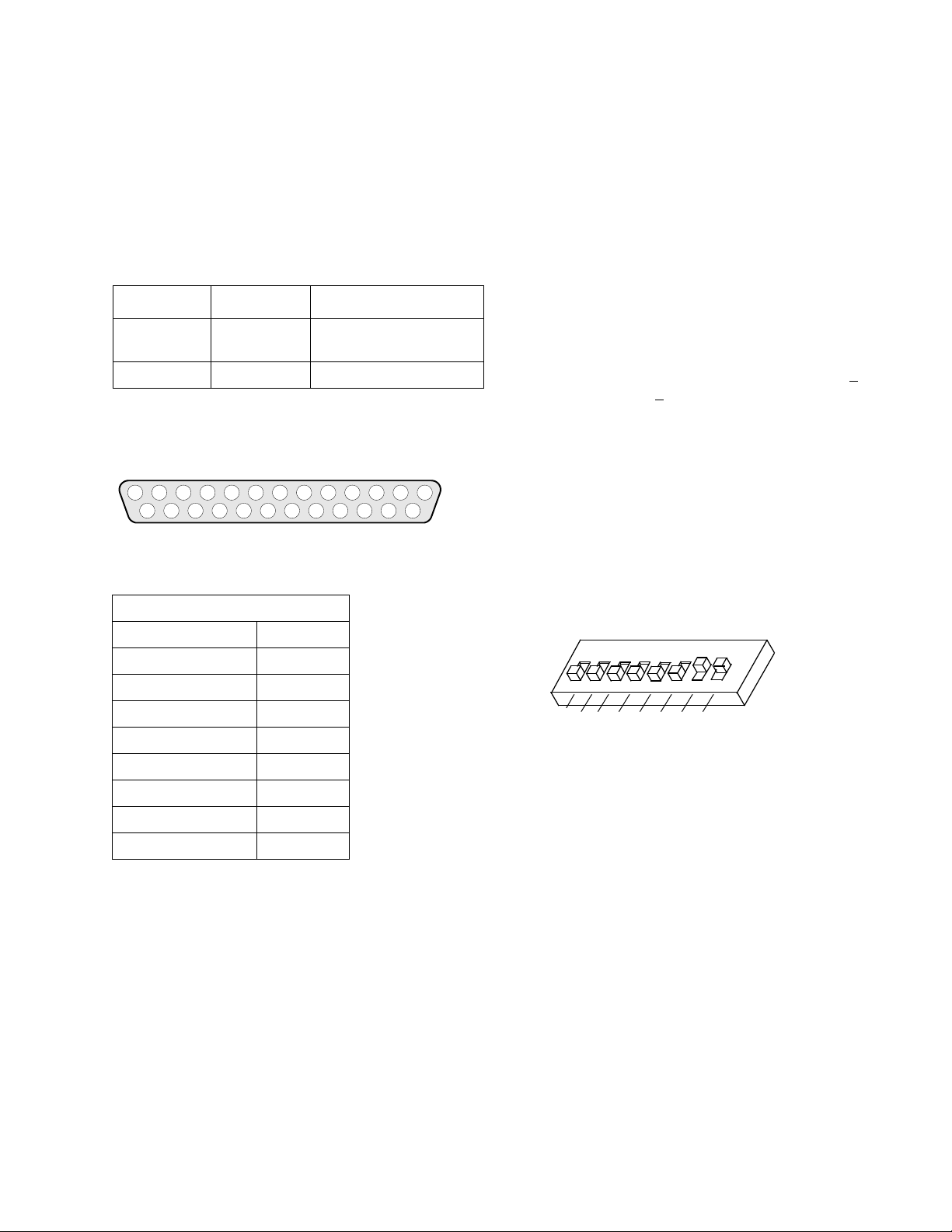
The 3282 interfaces with user equipment through the DB25 RS232 connector. See Figure 1 for pinout details
7 8 9 10 11 1265432 131
14 15 16 17 18 19 20 21 22 23 24 25
.
Figure 1 RS-232 Connector
Table 2 RS-232 CONNECTOR PINOUT
range of products. When used with DRL synthesized radios
(DL-3400 and JSLM/RNet) a shorter delay time (30ms) may
be used
(refer to Tables 2 through 4 and Figure 3). Follow
steps a through c under setup switch S101.
RECEIVE INPUT LEVEL
For proper operation of the modem, the carrier level from
the transceiver should be 35 mVrms -1mVrms (or 99 mVpp - 2.8 mVp-p). DRL transceivers (DL-3400) are factory
adjusted to provide a data level output to the modem of 707
mVrms (or 2 V p-p). The data level output to the modem
when used with the DRL JSLM/RNet is 212 mVrms +
mVrms (or 0.6 V p-p +
0.05 V p-p).
17.5
ADJUSTMENTS
There are two adjustments on the modem board. These
adjustments have been set at the factory and may require
further adjustment in the field for your application.
DIP Switch S101
Transmit Level Adjust R400
RS-232 PINOUT
1 Shield_GND J101-1
2 RS232_DCE RXD J101-2
3 RS232_DCE TXD J101-3
4 RS232_RTS J101-4
5 RS232_CTS J101-5
6 RS232_DSR J101-6
7 RS232_GND J101-7
8 RS232_DCD J101-8
20 RS232_DTR J101-20
DEFAULT FACTORY SETTINGS
Normal
Conventional
Bell 202
Half Duplex
Active High Squelch
FSK Audio
240 ms RTS to CTS Delay
100 mS Soft Carrier Turnoff debounce time
Transmit Input Level (pre-set for 400 mVrms)
S101
ON
1
1
0
P
L
3
O
0
A
1
O
/
N
L
2
/
O
0
I
L
2
T
A
L
N
M
L
E
R
E
V
L
B
O
N
N
E
O
U
C
Q
S
4
2
3
5
6
T
1
2
X
R
T
T
E
E
P
P
L
V
P
O
O
N
U
I
D
H
L
C
L
U
F
/
F
L
A
H
O
ON
8
7
3
T
P
Figure 2 DIP SWITCH S101 (DEFAULT SETTINGS)
SETUP SWITCH S101
a. To access S101 and make other adjustments, remove the
modem board from the housing by removing the 2 screws
on the RS-232 connector, the corner screws from the opposite end of the housing, and the top cover screw. Slide
the modem board out.
b. Set the switches as indicated in Tables 3 and 4 (0=Off,
1=On).
c. Re-install the modem board in the housing unless
performing adjustments described in the following two
sections.
The factory default setting for the RTS to CTS delay time is
set to the maximum delay for compatibility with a wide
1
1 Part No. 004-3282-004
TRANSMIT OUTPUT LEVEL
The transmit carrier level to the transceiver is factory preset
for 400 mVrms. This input level is required by a Dataradio
transceiver connected to the modem. To change the factory
input level, follow steps d through g:
d. If necessary, remove the modem board from the housing
as described in Step a.
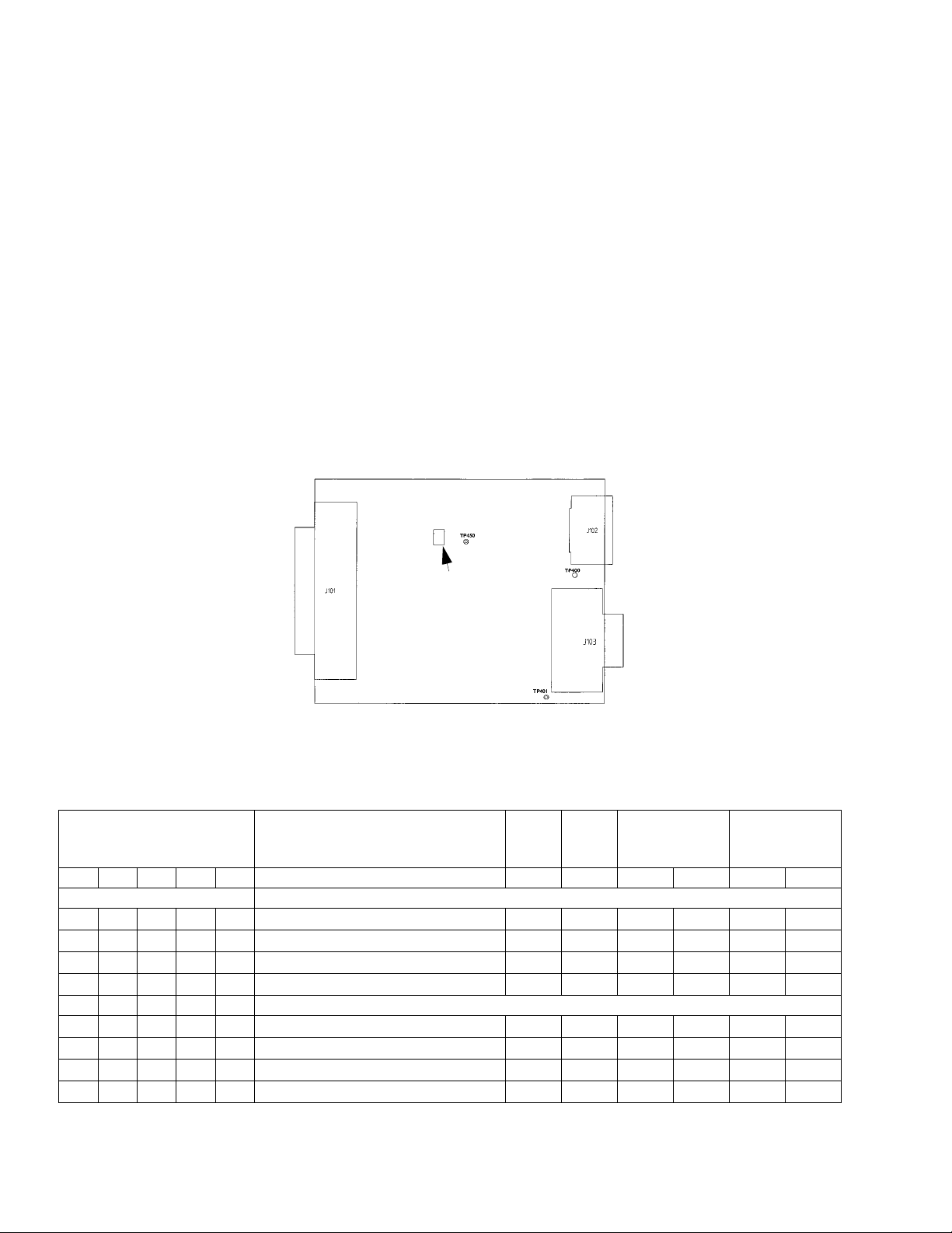
f. Monitor the AC voltage at TP400, J102. Adjust R400 for
400 mVrms if using a DRL telemetry transceiver. If
another transceiver is used, adjust R400 as required. J103
pin 5 has a resistor that will drop the Tx output level to
40 mVrms when connected to the DRL JSLM / RNet.
g. Re-install the modem board in the housing.
3282 LEDS
e. Configure the telemetry equipment connected to the RS-
232 jack to transmit a continuous data signal. If no
equipment is connected to the jack, configure S101 with
switches 1 and 7 ON. Then move switch 6 to ON to key-up
the modem. The modem will transmit a continuous
alternating space/mark tone from U230.
R400
Transmit Output
Level Adjust
Figure 3 ALIGNMENT POINTS
The 3282 has 2 LEDs (CR220) that are visible through the
adjustment hole in the case closest to the 10 pin connector.
One LED will flash green whenever the modem has power
and the microcontroller U220 is operating correctly. The
other red LED will be solid red whenever the modem is
transmitting.
A Tuning tool should be used to
perform adjustments on R400. This
tool is available from DRL’s
Customer Service as part number
721-0015-142S.
Table 3 SWITCH S101 SETTINGS FOR BELL 103/202
Full/
Half
Dup
Tx Freq Rx Freq
DIP Switch S101
Operating Mode
Baud
Rate
12345 SpaceMarkSpaceMark
(0=Off, 1=On) Normal Modes
0 - 1 - 1 Bell 103 Answer 300 Full 2025 2225 1070 1270
0 - 1 - 0 Bell 103 Originate 300 Full 1070 1270 2025 2225
0 - 0 - 1 Bell 202 Full-Duplex 1200 Full 2200 1200 2200 1200
0 - 0 - 0 Bell 202 Half-Duplex 1200 Half 2200 1200 2200 1200
12345 Loopback Modes
1 - 1 - 1 Bell 103 Answer Loopback 300 Full 2025 2225 2025 2225
1 - 1 - 0 Bell 103 Originate Loopback 300 Full 1070 1270 1070 1270
1 - 0 - 1 Bell 202 Main Loopback 1200 Full 2200 1200 2200 1200
1 - 0 - 0 Bell 202 Main Loopback 1200 Full 2200 1200 2200 1200
2Part No. 004-3282-004
 Loading...