

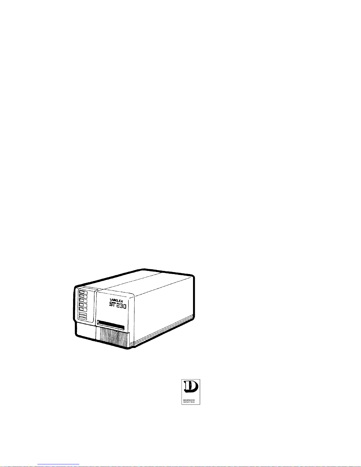
ST 230
USER
MANUAL
DATAPROCESS EUROPE S.p.A.
20082 Binasco (MI)
Viale dell'Artigianato, 19
Tel. 02 900221
Fax. 02 90091353

DATAPROCESS EUROPE S.p.A.
ST 230 USER MANUAL Pag.
1

DATAPROCESS EUROPE S.p.A.
ST 230 USER MANUAL Pag.
2
CONTENTS:
1 INTRODUCTION................................................................................................................4
2 PRODUCT DESCRIPTION................................................................................................5
3 TECHNICAL SPECIFICATIONS........................................................................................7
4 UNPACKING AND INSPECTION......................................................................................8
5 STORAGE AND TRANSPORT..........................................................................................9
5.1 TRANSPORT................................................................................................................9
6 WORKING PLACE..............................................................................................................9
7 ELECTRICAL CONNECTIONS .......................................................................................10
7.1 NOTICE FOR CUSTOMERS IN THE UNITED KINGDOM.........................................10
7.2 REAR PANEL, CONNECTION ....................................................................................11
8 BEFORE USE OPERATI ONS.........................................................................................12
9 THERMAL TRANSFER RIBBON LOADING PROCEDURE.........................................14
10 LABEL ROLL LOADING PROCEDURE......................................................................17
10.1 STRIP MODE LABEL ROLL LOADING......................................................................19
10.2 DISPENSING MODE LABEL ROLL LOADING...........................................................20
11 FINAL OPERATIONS....................................................................................................22
12 USE OF THE PRINTE R................................................................................................24
13 USE OF THE PRINTE R FRONT PANEL....................................................................26
13.1 OPERATIONS FROM FRONT PANEL.......................................................................29
13.2 ON LINE.......................................................................................................................29
13.3 PRINTING PHASE STOP AND RESTART.................................................................29
13.4 OFF-LINE PHASE.......................................................................................................30
13.5 PRINTING INTERRUPTION........................................................................................31
13.6 DEMO TEXTS.............................................................................................................31
13.7 MACRO SELECTION..................................................................................................32
13.8 SET- UP OR CONFIGURATION MODE.....................................................................32
13.9 BAUD RATE SELECTION ...........................................................................................33
13.10 CHARACTER FONTS MAP SELECTION...............................................................34
13.11 PRINT MARGINS SELECTION................................................................................34
13.12 PRINTING SPEED SELECTION.............................................................................35
13.13 PRINTHEAD TEMPERATURE ADJUSTMENT .......................................................35
13.14 LABEL CALIBRATION ..............................................................................................36
13.15 OPERATION MODE SELECTION..........................................................................37
13.15.1 Label mode/paper mode....................................................................................37
13.15.2 Ribbon Economizer enable/disable...................................................................37
13.15.3 Thermal Transfer and Direct Thermal selection...............................................37
13.15.4 Enable/Disable of the photodispenser sensor (optional)..................................38
13.16 PARAMETER RESET..............................................................................................38

DATAPROCESS EUROPE S.p.A.
ST 230 USER MANUAL Pag.
3
14 MAINTENANCE.............................................................................................................40
14.1 PRINTHEAD CLEANING.............................................................................................41
14.2 RUBBER ROLLS CLEANING.....................................................................................42
14.3 PAPER GUIDES METALLIC SHAFTS CLEANING....................................................42
15 TROUBLE SHOOTING ................................................................................................43
16 APPENDIX A..................................................................................................................46
16.1 SERIAL CABLE PINOUT.............................................................................................46

DATAPROCESS EUROPE S.p.A.
ST 230 USER MANUAL Pag.
4
1 INTRODUCTION
The present manual contains information and advice that has to be followed in order to
ensure a safety use of the printer.
It is recommended to proceed with periodical maintenance and, if necessary, to send faulty
parts back to our distributor, as they are equipped with appropriate tools and specialised
personnel able to operate following the instructions of the manufacturer specialists.
ST 230 has to be installed following the here below instructions.
In case of mal - function contact the authorised distributor directly.
DATAPROCESS EUROPE S.p.A. is not responsible in case of maintenance carried out by
non authorised personnel or if the instructions in the present manual are not correctly
followed.
DATAPROCESS EUROPE S.p.A.
ST 230 USER MANUAL Pag.
5
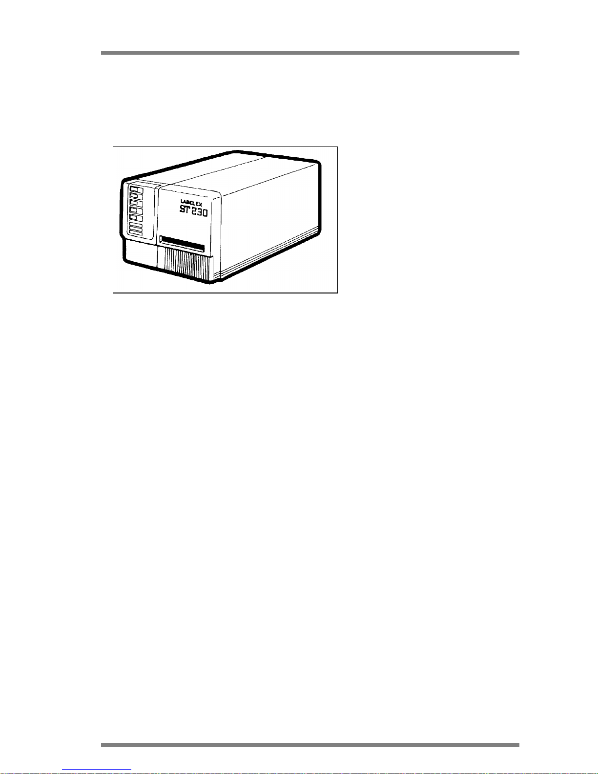
2 PRODUCT DESCRIPTION
ST 230 is a label and slip overprinter to be used either in thermal transfer or direct thermal
mode.
The printer has been designed and
manufactured for use in industrial
applications where structure solidity is
essential for high-volume production.
Installation does not require special
technical knowledge and/or special
tools, please follow carefully
instructions in paragraph 7 of the
present manual.
Picture 1
Mechanical regulations are not required. Follow the instructions (see paragraph 13.14) for
automatic calibration of label photosensor.
The only operation before use is the label and ink ribbon roll loading (see relative paragraph).
ST 230 is available with a range of accessories that give more flexibility (see table page 4).
DATAPROCESS EUROPE S.p.A.
ST 230 USER MANUAL Pag.
6
ST 230 ACCESSORIES TABLE
ACCESSORY DESCRIPTION
SOFTWARE LW230
PC graphics software MS DOS, it allows to
create and print the label.
CUTTER
Allow to produce tags and tickets from
continuous paper roll.
UNWINDER/REWINDER
Allow to unwind labels roll up to 250 mm of
diameter. A motor driven front rewinder
designed to rewind labels roll up to 250 mm of
diameter.
WINDOWS DRIVER
WinLW
PC graphics software Windows98, it allows to
create and print the label.
For further details see the Instructions of the accessories.

DATAPROCESS EUROPE S.p.A.
ST 230 USER MANUAL Pag.
7
3 TECHNICAL SPECIFICATIONS
PRINT MODE: Thermal transfer and direct thermal on thermal paper
PRINTING RESOLUTION: 6 dot/mm or 8 dot/mm
PRINT AREA SIZE: Up to 105 mm (6 dot/mm)
Up to 112 mm (8 dot/mm)
LABEL SIZE:
LENGTH: From 10 to 408 mm (6dot/mm) and from 10 to 287 mm (8dot/mm)
WIDTH: From 40 to 120 mm
LABEL ROLL SIZE: 150 mm maximum outside diameter
PRINT SPEED: Up to 125 mm/s (6 dot/mm), 100 mm/s (8 dot/mm),
regardless of text complexity.
PAPER FEED: Up to 180 mm/s
FONTS: Three standard alphanumeric fonts, two graphics fonts (logos and
symbols); 5 proportionally spaced fonts expandable from 0,8 x
1,2 mm to 110 x 95 mm.
BAR-CODES: Code 39, Code 93, 2/5 interleaved, Codabar, EAN 8, EAN 13,
EAN 128, UPC A, UPC E, Code 128, ADD_ON, ITF 14, ITF 16.
PRINTING ROTATION: 0°, 90°, 180°, 270°.
INTERFACE: RS 232 C, baud rate from 300 to 38400 bauds
XON/XOFF or CTS/RTS protocol
OVERALL SIZE: 280 mm x 210 mm x 460 mm
POWER SUPPLY: 220V +10% -15% single phase 50 Hz.
110 V (60 Hz) and 240 V version on request.
DATAPROCESS EUROPE S.p.A.
ST 230 USER MANUAL Pag.
8
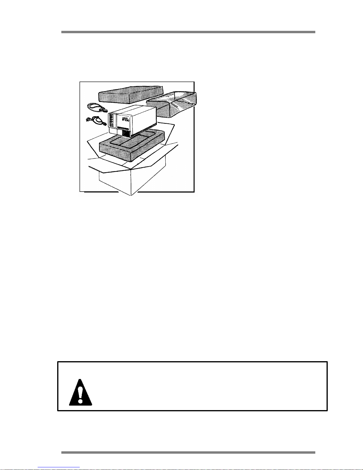
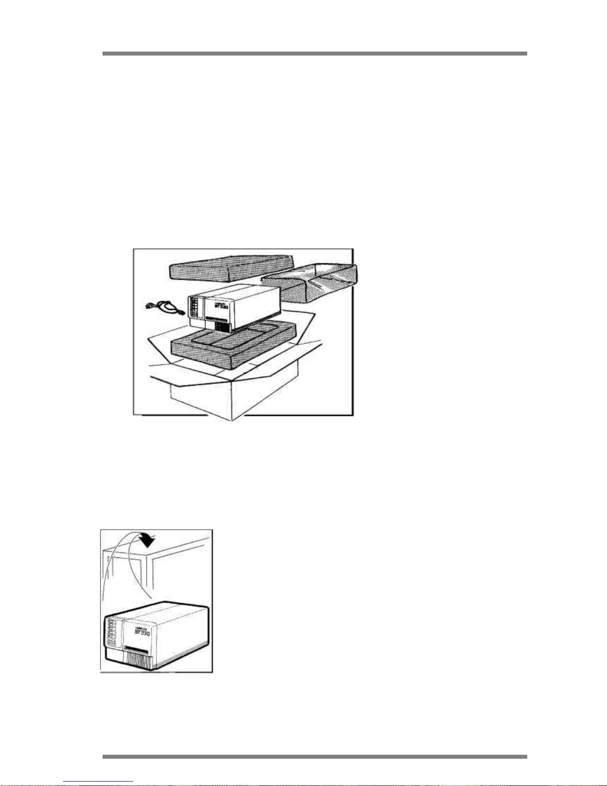
4 UNPACKING AND INSPECTION
Open the packaging and check the following standard components:
1. ST 230 Printing mechanism
1. ST 230 User manual
1. Power cord
1. Anti-dust cover
Components inside the printer:
• Thermal/transfer ribbon cartridge
• Thermal/transfer ribbon rewind
clamp
• Ribbon roll locking pin
• Silicon paper locking clamp on the
rewinder
Picture 2
Save the packaging units and the non-impact material, to be used in case of returning the ST
230 printer or for internal moving.
Inspect the packaging to ensure that non damage did not incur during transport, and in
particular:
• check the external part of the printer
• open the side port to verify possible internal damage.
In case of damage.
• Notify the carrier directly, giving details about the damage
• Keep the whole packaging unit available for the inspection by the transporter
• Notify the transporter in writing and send a copy to DATAPROCESS EUROPE S.p.A.
or its distributor, indicating the amount of the damage.
IMPORTANT: DATAPROCESS EUROPE S.p.A is not responsible for
damages incurred during transport and is not authorized to
replace or repair under warranty.
DATAPROCESS EUROPE S.p.A.
ST 230 USER MANUAL Pag.
9
5 STORAGE AND TRANSPORT
In case of non immediate use the ST 230 should be stored within its original
package. The environmental conditions for storage are the following:
• Temperature from 5° C to 40° C
• Humidity: 20% to 90% non condensing.
5.1 TRANSPORT
In order to provide a safe moving of the printer follow the below instructions:
• Disconnect the printer from
the power supply (see
paragraph 7)
• Disconnect the data cable
from the serial port of the
printer
• Verify that both side and front
cover are closed.
Pack the printer as indicated in
picture 3 on your left.
Picture 3
6 WORKING PLACE
ST 230 can be installed on any flat surface able to support the weight of 17 Kg and of
dimensions to adequately locate the printer and its accessories as
indicated in picture 4 on your left.
It is recommended to leave an area around the unit sufficient to
warranty enough to maintain the working temperature within
specification.
Picture 4
DATAPROCESS EUROPE S.p.A.
ST 230 USER MANUAL Pag.
10
7 ELECTRICAL CONNECTIONS
The power cable of the printer has a female connector on one side and on the opposite pole
a spindle type "SCHUKO".
To provide a correct and safe
connection to the electrical network
follow the here below instructions,
as indicated on picture 5 on your
left:
1. Insert the female connector into
the proper plug mounted on the
rear panel of the printer.
Picture 5
2. Connect the spindle "SCHUKO" to an appropriate socket outlet with following voltage:
220 VAC +10% - 15% - 50/60 Hz.
The following voltages : 110 VAC and 240 VAC 50/60 Hz as per required
WARNING: Be sure that the power cord is connected to an electri-
cal installation with proper earthing.
Such electrical installation as per CEE safety rules.
7.1 NOTICE FOR CUSTOMERS IN THE UNITED KINGDOM
WARNING: If the plug supplied is not suitable for the socket outlets
in your factories, it should be cut off and an appropriate
plug fitted in accordance with the following instruction:
IMPORTANT: The wires in these mains lead are coloured in accor-
dance with the following code:
• GREEN and YELLOW : EARTH
• BLUE : NEUTRAL
• BROWN : LIVE
1
2
DATAPROCESS EUROPE S.p.A.
ST 230 USER MANUAL Pag.
11
As the colours of the cores in the mains lead of this equipment may not correspond
with the coloured marking identifying the terminals in your plug, proceed as follows:
• The core which is coloured green and yellow must be connected to the terminal in
the plug which is marked with letter "E" or by the earth symbol
, or coloured green and yellow.
• The core that is coloured blue must be connected to the terminal that is marked
with letter "N" or coloured black.
• The core that is coloured brown must be connected to the terminal that is marked
with letter "L" or coloured red.
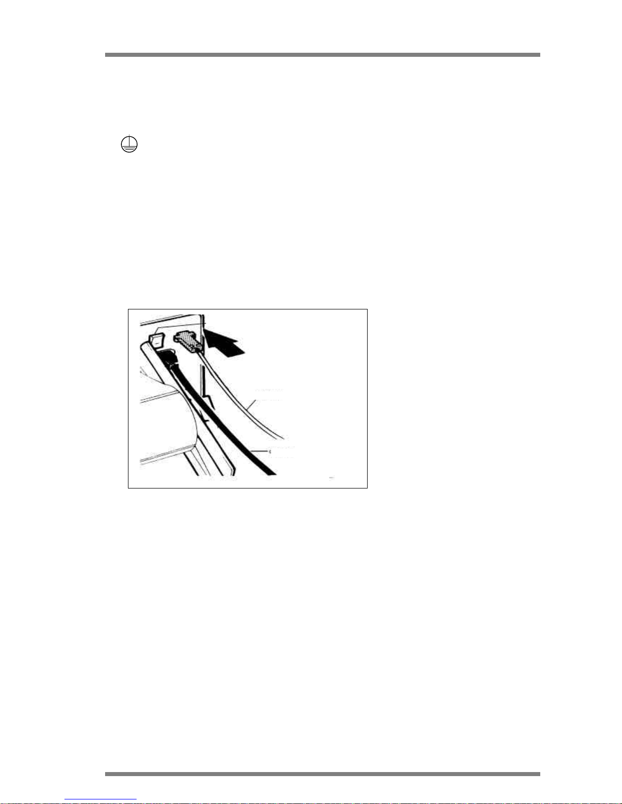
7.2 REAR PANEL, CONNECTION
Connect the printer with the
standard supplying cable, fol-lowing
instructions in para-graph 7.
To interface the printer to an
external driving device (PC, etc.)
use a serial cable with connector
(type D, 9 pin male). See appendix
A for the pin number of the serial
cable.
Before switching the device ON
press the switch button (when
Picture 6
off it shows one red "O"), verify that the cable is correctly
inserted as described on paragraph 7.
Picture 6 shows the rear panel and its connections.
POWER SWITCH
SERIAL CABLE
POWER CORD
DATAPROCESS EUROPE S.p.A.
ST 230 USER MANUAL Pag.
12
8 BEFORE USE OPERATIONS
WARNING: Before proceeding with the here bel ow instructions,
switch off the printer by pressing the power switch
(indicated on paragraph 7.2) and disconnect the spindle SCHUKO of the power cable from the plug (as in-
dicated in paragraph 7 point 2).
Open the lateral cover as indicated in the picture below.
Picture 7
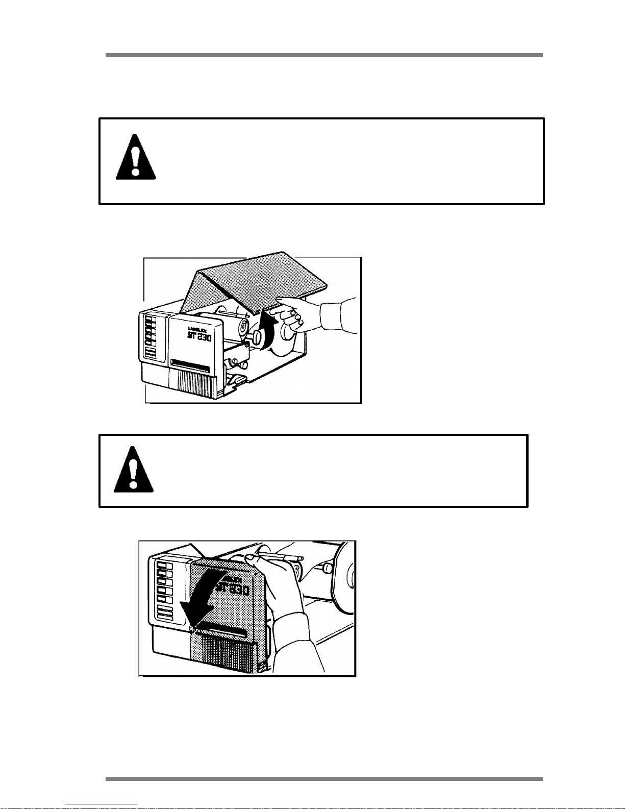
WARNING : Before working inside the printer be sure that the
cover is completely open.
Then, open the plastic grey front
cover rotating it downward, as
indicated in picture 8 on your left.
Picture 8
DATAPROCESS EUROPE S.p.A.
ST 230 USER MANUAL Pag.
13
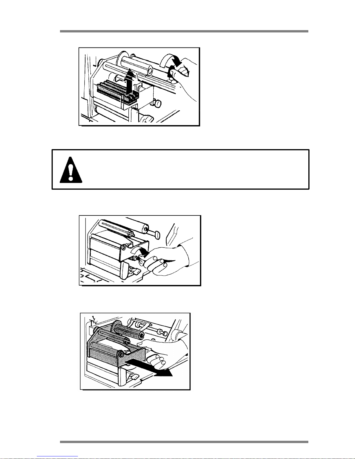
Now lift up the printhead from the
printing position rotating the black
knob half way as indicated in picture
9 on your left.
Picture 9
WARNING: Be careful not to put fingers between printhead and
rubber roll.
On the side of the reloadable
cartridge there is a knurled knob,
unlock and turn it completely in order
to unlock the cartridge, as indicated in
picture 10 on your left.
Picture 10
Take away the cartridge from its housing
pulling it out from the printer as indicated
in picture 11 on your left, and put it on the
work table.
Picture 11
DATAPROCESS EUROPE S.p.A.
ST 230 USER MANUAL Pag.
14
9 THERMAL TRANSFER RIBBON LOADING PROCEDURE
WARNING: The cartridge is a very delicate mechanical component
and it is therefore advisable to treat it with great care
in order not to incur damage of the components.
Take one roll of thermal transfer ribbon
"FOIL" and insert it on support holder
as indicated in picture 12 on your left.
Picture 12
IMPORTANT: Small dimension foil should be centered on the
cartridge and also remember that the foil is anti clockwise wound.
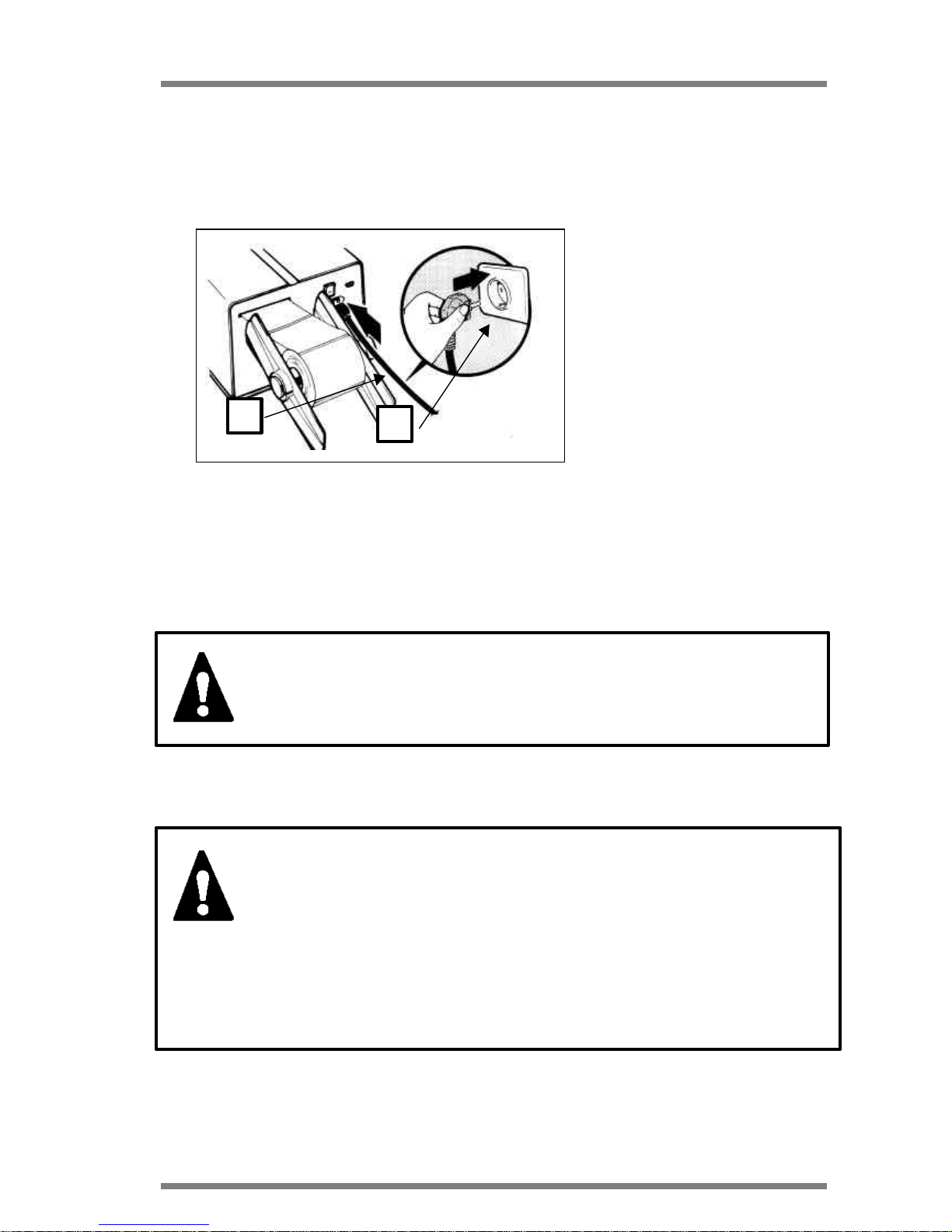
Fasten the steady pin to one of the four
holes on the supporting axis, choosing
the hole that permits a better blocking
of the ribbon, as indi-cated in picture 13
on your left .
If the ribbon is not perfectly fixed on the
supporting axis, the print quality may
be altered.
Picture 13

DATAPROCESS EUROPE S.p.A.
ST 230 USER MANUAL Pag.
15
Take the starting part of the ribbon,
generally a transparent strip, and pass
it over the cartridge so that it passes all
the aluminium pivots externally, and
between the metallic blade fixed to the
knurled knob and the pivot as indicated
in picture 14.
Picture 14
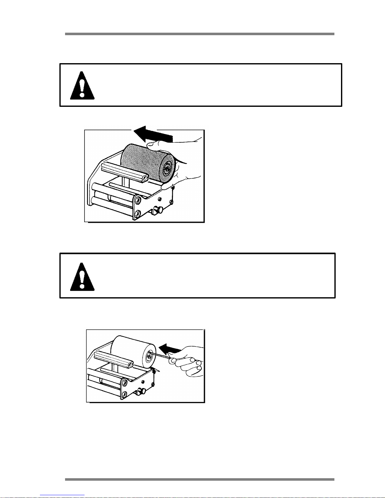
Wind the ribbon for two or three cycles
around the rewinding shaft as
indicated in picture 15 on your left. The
arrow shows the direction of ribbon
rewinding.
Picture 15
Insert the appropriate blocking ribbon in
its housing as indicated in picture 16 on
your left.
Picture 16

DATAPROCESS EUROPE S.p.A.
ST 230 USER MANUAL Pag.
16
Wind the ribbon for some turns around
the rewinding shaft till the transparent
strip is completely rewound and the
inked part is
present as indicated in picture 17 on
your left.
Picture 17
See paragraph 11 for loading the cartridge in the machine.

DATAPROCESS EUROPE S.p.A.
ST 230 USER MANUAL Pag.
17
10 LABEL ROLL LOADING PROCEDURE
Open the covers, lift the printhead and take off the printhead following the instructions in
paragraph 8.
Take the black flange away from the roll
holder as indicated in picture 18 on
your left.
Picture 18
Insert the labels roll on the roll holder,
as indicated in picture 19 on your left.
Picture 19
Take the strip of labels and let it pass
through under the black magnet brake
and adjust the width of the paper guide
to adapt it to the label width, turning the
knurled knob clockwise or
anticlockwise to widen or stretch the
device as indicated in picture 20 on
your left.
Picture 20

DATAPROCESS EUROPE S.p.A.
ST 230 USER MANUAL Pag.
18
Adjust the width of the low paper
guide following the above - mentioned instructions and be sure that
the paper passes inside the
photosensor located on the low
paper guide as indicated in the
square reported on picture 21 on
your left.
Picture 21
Pay attention not to tighten the
paper guides too much as indicated in picture 22 on your left.
Picture 22
Insert the flange on the roll holder
as indicated in picture 23 on your
left.
Picture 23

DATAPROCESS EUROPE S.p.A.
ST 230 USER MANUAL Pag.
19
After the above - mentioned preliminary phases, go through the procedures to insert the
paper to operate in one of the following printing modes:
• STRIP MODE
• DISPENSING MODE
10.1 STRIP MODE LABEL ROLL LOADING
This operating mode is generally
used when it is not required to print
a large quantity of labels and
therefore the printed labels can fall
down.
After the paper has passed
through the paper guides it has to
pass between the printhead and the
rubber roll as indicated in picture
24 on your left.
Picture 24
It is advisable to open the blocking
mechanism by turning the red knob
located under the printhead
clockwise as indicated in picture 25
on your left.
Picture 25

DATAPROCESS EUROPE S.p.A.
ST 230 USER MANUAL Pag.
20
10.2 DISPENSING MODE LABEL ROLL LOADING
This operating mode is generally used when it is required to dispense the labels (that is
detaching from silicon paper) after the printout in order to stick them manually on the
object to be labelled as indicated
in the picture on your left. In this
case the printer has to be
equipped with a label
photosensor. After the paper has
passed through the paper guides
it has to pass between the
printhead and the rubber roll as
indicated in
picture 26 on your left.
Picture 26
Take away the labels from about
400 mm of material and detach all
the labels located on the strip, as
indicated in picture 27 on your left.
Picture 27
Pass the silicon paper only under
the rubber roll as indicated in
picture 28 on your left.

DATAPROCESS EUROPE S.p.A.
ST 230 USER MANUAL Pag.
21
Picture 28
Attach the silicon paper to the
rewinder shaft by winding it
approximately two or three turns as
indicated in picture 29 on your left.
Picture 29
Lock the paper on the rewinder
with the paper clamp as indicated
in picture 30 on your left.
Picture 30
Turn the red paper locking mechanism knob completely clockwise as indicated in picture 31 on
your left.
Picture 31

DATAPROCESS EUROPE S.p.A.
ST 230 USER MANUAL Pag.
22
11 FINAL OPERATIONS
After installing the labels following
one of the above - mentioned
modes or a new thermal transfer
ribbon the operator has to reinstall
the cartridge (in case it has been
taken off, only for inked ribbon
installing), being careful to insert all
the three guides on the appropriate
housings as indicated in picture 32
on your left.
Turn the knurled knob anticlockwise to lock on its housing.
Picture 32
Lower the printhead and reposition it in printing position, turning
the black knob anti-clockwise as
indicated in picture 33 on your left.
Picture 33
WARNING: Be careful not to put fingers between printhead and
rubber roll.

DATAPROCESS EUROPE S.p.A.
ST 230 USER MANUAL Pag.
23
Close the covers of the printer,
starting from the front one paying
attention to insert the labels in the
appropriate slot and than lower the
side cover as indicated in picture
34 on your left.
Picture 34
WARNING: During closing procedure the side cover has to be
helped.

DATAPROCESS EUROPE S.p.A.
ST 230 USER MANUAL Pag.
24
12 USE OF THE PRINTER
After switching on, the printer will proceed with a self test procedure that takes some
seconds: all the leds of the front panel will turn on and then off (with exception of the red one
indicating printer on), after the printhead is lifted up and lowered, then one test label is printed
as indicated in the picture below.
If the above - mentioned procedure is well executed, the ON LINE led will light up and the
printer is ready to execute the commands received by the driving device through serial line.
The test label (printed when the printer is on) contains the following information:
LABEL TEST
ST 230 B5.3.
KIND OF PRINTHEAD AND TEMPERATURE OF THE PRINTHEAD IN
DEGREES CENTIGRADE
TEST TO VERIFY THE
FUNCTION AND
ALIGNMENT OF THE
PRINTHEAD COMPOSED
OF A BLACK AREA, ONE
GREY AREA AND
VERTICAL AND
HORIZONTAL LINES.
$&%0000000000000000
K1001J1806V05065730
P098H0039G00360000
N00000000 BR=2 CM= 7 NA=00
where:
$&% - abled functions
K - operating mode
J - printing speed and aspect ratio
V - Paper feed speed and printhead energy
P - Label photosensor sensitivity
H - Label positioning with respect of printhead
G - Printout area
N - Cutter and applicator parameters
BR - Baud rate (serial line speed communication)
CM - Fonts map
NA - Network address
6 dots/mm 29° C
PRINTER MODEL AND FIRMWARE VERSION
CURRENT VALUE OF THE PARAMETERS ON THE
NON VOLATILE MEMORY

DATAPROCESS EUROPE S.p.A.
ST 230 USER MANUAL Pag.
25
The format used to represent values $&%, K, J, V, H, G, N is the same used by the
corresponding commands that can be sent from the external driving device, while
parameters BR, CM, NA are settable only by front panel in configuration mode.
The complete description of the commands reported on the test label as indicated in the
"PROGRAMMING GUIDE".

DATAPROCESS EUROPE S.p.A.
ST 230 USER MANUAL Pag.
26
13 USE OF THE PRINTER FRONT PANEL
Printer ST 230 is equipped with a command front panel, composed of a serie of buttons
and leds that permit the printer parameters to be programmed.
Examining in detail the front panel
there are four keys:
ON LINE
THERM/TRANSF
HEAD LIFT
RIBBON/ECONOM
Each equipped with green LED
One key (FEED) key without LED
Three green LEDS
END PAPER/RIB.
PAPER MODE
PHOTO ON
And a red led (ON), indicating the status of the printer:
RED LED ON = PRINTER SWITCHED ON
RED LED OFF = PRINTER SWITCHED OFF
In the following pages there is a map of the light leds showing the different functions:

DATAPROCESS EUROPE S.p.A.
ST 230 USER MANUAL Pag.
27
LIGHT LEDS TABLE
LIGHT LED STATUS MEANING
ON
OFF
FLASH
The printer in ON LINE status and is ready to
execute the commands coming from serial line.
The printer can be both in printing status or in
OFF LINE. It is not possible to execute line
commands that will be stored on the buffer with
exception of those executable in real time.
The printer can be both in printing status or in
OFF LINE. It is not possible to execute line
commands that will be stored on the buffer with
the exception of those executable in real time.
ON
OFF
The printer is ready to print in thermal/transfer
mode.
The printer is ready to print in direct thermal
ON
OFF
The printhead is lifted by its motor and the
printer is ready to execute special functions.
The printhead is in contact with the paper
(normal functioning mode).
ON
OFF
The economizer device is abled.
The economizer device is disabled.

DATAPROCESS EUROPE S.p.A.
ST 230 USER MANUAL Pag.
28
LIGHT LED STATUS MEANING
ON
OFF
FLASH
End paper and/or inked ribbon, or feed error
Normal working
Temporary stop of printing due to printhead
overheating.
ON
OFF
The printer is ready to print continuously.
The printer is ready to print on labels or to
detect the tag in order to maintain the printing
feed.
ON
OFF
FLASH
The label's photosensor (optional) is abled.
The label's photosensor (optional) is disabled.
During the print out the machine is waiting for
the printed label to be removed in order to print
the next one (only if the label photosensor is
abled).

DATAPROCESS EUROPE S.p.A.
ST 230 USER MANUAL Pag.
29
13.1 OPERATIONS FROM FRONT PANEL
The operations from front panel can be divided in three phases:
• ON LINE
• OFF LINE
• SET UP or configuration
13.2 ON LINE
The printer is in ON LINE after switching on phase, as per instructions in paragraph
12 and the light leds on the front panel will show information on the status of the
printer (see instruction on LED TABLE on page 25 and 26).
The only key abled during this phase is the ON-LINE one that when pressed the
machine is OFF-LINE (ON-LINE led off) after being
executed the print-out in course.
13.3 PRINTING PHASE STOP AND RESTART
During printing phase, pressing the ON-LINE key printing is suspended and the
printer is on OFF-LINE at the end of the current
label. By pressing the key a second time the printout
re-start from the interruption point.

DATAPROCESS EUROPE S.p.A.
ST 230 USER MANUAL Pag.
30
This is also valid when the interruption is caused by an error (once removed the
cause).
13.4 OFF-LINE PHASE
To execute the operations below it is necessary to have the printer in OFF-LINE
status (following instructions on paragraph 13.2).
The printer can pass spontaneously in OFF-LINE status during the printing in
course in case of errors (for example : end paper, end ribbon).
During this phase from front panel it is possible to select the following operations:
PRINTHEAD LIFT
It is made by pressing the HEAD LIFT key and
is an alternative to the manual lift with the
appropriate knob.
COPY LAST LABEL
It is made by pressing the FEED key, to have
a printing test or to realign the paper after
replacement.
PRINT MODE SELECTION
It is made by pressing the THERM TRANSF key
and is indicated by lighting of it's led (see
description of led function).

DATAPROCESS EUROPE S.p.A.
ST 230 USER MANUAL Pag.
31
ECONOMIZER SELECTION
It is made by pressing the RIBBON ECONOM
key and is indicated by the light of the relative led
(see description of light led function).
13.5 PRINTING INTERRUPTION
The following procedure permits the termination of one session of printing before
the end of the number of labels ordered. By pressing ON
LINE to suspend (see paragraph 13.4), then by pressing
the HEAD LIFT,FEED, HEAD LIFT keys one after the
other, the residual number of labels is zero.
By pressing the ON LINE key again the printer is ready to
accept other commands.
13.6 DEMO TEXTS
A serie of demo texts is included in the printer program.
Texts are acceptable by command via serial line and also
by front panel following the here below procedure.
Keep the printer in OFF-LINE mode pressing the ON-
LINE key (following instruction on paragraph 13.4).
Then press the HEAD LIFT, RIBBON ECONOM keys one
after the other. The RIBBON-ECONOM key pressed once, twice,three times
permits the selection of the first, second, third etc. demo text.

DATAPROCESS EUROPE S.p.A.
ST 230 USER MANUAL Pag.
32
Once the selection is made, press the HEAD LIFT key and ON
LINE key again in order to have the elaboration and the
printout of the desired text.
13.7 MACRO SELECTION
It is possible to insert, in a proper EPROM memory, a series of further texts (up to a
maximum of 99) or, generally, command sequences (MACRO) in order to
personalise the printer to specific operations. Texts are acceptable by command
via serial line and also by front panel following the here below procedure.
Keep the printer in OFF-LINE mode pressing the ON-
LINE key (following instruction on paragraph
13.4).Then press sequentially keys HEAD LIFT,
THERM-TRANSF.
Key THERM-TRANSF pressed once, twice, three times permits the selection of
the first, second, third macro text.
Once the selection is made, press the HEAD LIFT key and ON-
LINE again sequentially in order to have the elaboration and the
printout of the desired text.
13.8 SET- UP OR CONFIGURATION MODE
It is also possible to vary the configuration of the printer from front panel following
the here below instructions.
1. Switch the printer ON following the instructions in paragraph 7.1, keeping the
ON-LINE key pressed till the printer completes the switching on phase in
paragraph 12 and release it after a few seconds when the leds are ON for the
second time. All the light leds are off (with the exception of the red one) and the
printer is in configuration mode.

DATAPROCESS EUROPE S.p.A.
ST 230 USER MANUAL Pag.
33
2. Press the ON-LINE key to and the printer is OFF-LINE.
Then press the key HEAD LIFT and then the ON-LINE key.
All the leds are off (with the exception of the red one) and the
printer is in confi-guration status and you can be selected the
parameters here below.
Not all the parameters
available are selectable in
that way, while, viceversa, some parameters (BAUD RATE, FONT MAP,
NETWORK ADDRESS) are accessible exclusively throughout panel and not from
serial line.
• Pressing the ON LINE key again the current parameter values are memorized
(all the leds are ON for some seconds). Then pressing the HEAD LIFT and ON
LINE key the printer is ready to receive other commands.
13.9 BAUD RATE SELECTION
Select the printer in configuration mode (as described in paragraph 13.8) then
press the RIBBON ECONOM key (the respective led is
turn on). Than press the FEED key.
Every time the FEED key is pressed increases the
parameter BR, starting from current value till value 7, to restart then at 0,
alternatively.
Value's BR corresponds to the following BAUD RATES:
BR BAUD RATE
0 38400
1 19200
2 9600
3 4800
4 2400
5 1200
6 600
DEFAULT BAUD RATE

DATAPROCESS EUROPE S.p.A.
ST 230 USER MANUAL Pag.
34
7 300
Press the RIBBON ECONOM key again to complete the selection: it is printed a
test label with the updated BR value. At this moment, exit from configuration mode
(as described in paragraph 13.8) and switch the printer off so that the new BAUD
RATE is operative.
13.10 CHARACTER FONTS MAP SELECTION
Select the printer in configuration mode (as described in paragraph13.8) then press the
RIBBON ECONOM key (the respective led is turn on).
Then press the HEAD LIFT key.
Every time the HEAD LIFT key is pressed increases the
parameter CM, starting from current value till value 9, to
restart then at 0, alternatively.
Press the RIBBON ECONOM key again to complete the selection: it is printed a test
label with the updated CM value. At this moment you have to exit from configuration
mode (as described in paragraph 13.8) so that the new modifications are operative.
The font map permits to personalize the printers relating to the
language required, generally the printer is set with CM=7 to indicate that the map in use
is the IBM PC one.
13.11 PRINT MARGINS SELECTION
Select the printer in configuration mode (as described on paragraph13.8) then press the
RIBBON ECONOM key (the respective led is turn on). Now
pressing the ON LINE and THERM TRANSF keys it is
possible respectively to tighten and widen, of 1 mm step
each, the side margin of printing zone, till a correct centering
is reached, with the help of the printed liner at each pression,
the margins relating to width of the mounted label.

DATAPROCESS EUROPE S.p.A.
ST 230 USER MANUAL Pag.
35
Pressing RIBBON ECONOM again, the selection stops and a test label is printed where
the width of the central zone (black, grey and bars) it adjust to the value given to the
margins always keeping itself centered with respects to the printhead. The adjustment of
margins is of help to avoid any possible ink stains on the rubber roll in case of using
narrower labels compared to the previous label width. In case of using different label
formats it is useful to leave the printer set with margins corresponding to the narrower
one sending time by time from line the correct command on the basis to the text to be
printed. At this point exit from configuration mode (as described in paragraph 13.8) in
order to execute the modifications programmed.
13.12 PRINTING SPEED SELECTION
Select the printer in configuration mode (as described in paragraph 13.8) then
press the THERM TRANSF key (the respective led is turn
on). Then press the FEED key.
Now, each pression of the FEED key the printer chooses
in turn one of the three different pre-set speed (the speed
values are reported on parameter J and are
1204, 1806, 2709 for the 6 dots/mm and 1105, 1306
2210 for the 8 dots/mm), printing a test label each time
to certify the selection result.
Pressing RIBBON ECONOM again, the selection stops
and a test label is printed containing the values set. At this point exit from
configuration mode (as described in paragraph 13.8) in order to execute the
modifications programmed.
13.13 PRINTHEAD TEMPERATURE ADJUSTMENT
Select the printer in configuration mode (as described in paragraph 13.8) then
press the THERM TRANSF key (the respective led is turn
on).
Concerning the temperature (printhead power), the ON
LINE key permits a rough adjustment, in turn among 5 prefixed values for the 6 dots/mm printhead (4 for the 8
dots/mm printhead) while the HEAD LIFT and RIBBON ECONOM keys permit a
+ 1 mm
- 1 mm

DATAPROCESS EUROPE S.p.A.
ST 230 USER MANUAL Pag.
36
fine adjustment, respectively to up and down of 10mW each time.
Each key pression a test label is printed that shows the variation.
It is always advisable to operate at the minimum speed in case of rough
temperature adjustments to avoid any possible burns of the ribbon during the
passage of values. Now exit to the configuration mode (as described in paragraph
13.8) in order to execute the modifications programmed.
13.14 LABEL CALIBRATION
Select the printer in configuration mode (as described in paragraph 13.8) then
press the FEED key. Two white labels are ejected and
than a test label is printed containing all the values of
parameters P and H updated referring to the kind and
length of the label correctly mounted on the printer.
Value P is proportional to the transparency of the used
material, measured before feeding paper : it is important that in case of pre-printed
labels the paper is initially positioned in the way that under the sensor is present a
light zone and that the sensor is not reading on the gap between labels. Valid
values of P are from 52 to 255 (normally from 60 to 120), whilst extreme values of
51 or 256 indicate generally a malfunctioning, due to the absence or excess of
sensored light. Values near or exceeding 200 indicate a wrong starting position of
the paper (reading on the gap between the labels) or the use of materials very
transparent that can constitute a problem for a correct step maintaining.
The value H represents the feed paper (in dots) made from when the edge of the
label has been detected by the sensor, to correctly align the label under the printhead: these value changes relating to the height of the labels in use. The printer
calculates automatically with a certain approximation (generally less) the value
adapt to start printing from the upper edge of the label.
In case the FEED key is kept pressed, after ejecting the two white labels and
before the test print-out, the paper is fed slowly, increasing the value of H and,
therefore, lowering the starting point with respect of the edge till the key is left. This
is useful to make a fine adjustment and to find the correct label stop position to
allow the easy detachment in case of dispensing mode (with silicon paper
rewinding). In case of use of different label formats with frequent passage from one
to the other it is not easy to make a new adjustment at each label format: it is
advisable in this case to take note of P and H value reached initially for each used
+ 10 mW
- 10 mW

DATAPROCESS EUROPE S.p.A.
ST 230 USER MANUAL Pag.
37
format and than to include the set commands of the correct values sent for the
printout of each label to reach the automatic alignment of the printout.
13.15 OPERATION MODE SELECTION
Select the printer in configuration mode (as described in paragraph 13.8) then press the
HEAD LIFT key (the respective led is turn on). Now, the other
light leds of the panel indicate the operative mode selected
that can vary as follows:
13.15.1 Label mode/paper mode
Press the FEED key: light led PAPER MODE lights when in
paper mode whilst it is off in label mode.
13.15.2 Ribbon Economizer enable/disable
Press the RIBBON ECONOM key: the corresponding light
led will light when the Ribbon Economizer is abled, whilst
when it is off the economizer is disabled.
13.15.3 Thermal Transfer and Direct Thermal selection

DATAPROCESS EUROPE S.p.A.
ST 230 USER MANUAL Pag.
38
Press the THERM TRANSF key: the corresponding led lights
in Thermal Transfer, whilst when it is off is in direct thermal.
13.15.4 Enable/Disable of the photodispenser
sensor (optional)
Press the ON LINE key: the corresponding led indicated the
status.
NOTE: that there are two different status corresponding to the photosensor abled, depending on the
further check of correct dispensing is excluded (first pression) or abled (second
pression).
Pressing HEAD LIFT key again, the selection stops and a test label is printed con-
taining the values set. At this point exit from configuration mode (as described in
paragraph 13.8) in order to execute the modifications programmed.
13.16 PARAMETER RESET
The printer parameters can be modified by the operator to adapt the printer to the
proper requirements, nevertheless in case the printer has been programmed with
the wrong parameters the operator has to follow the here below procedure to zero
them and return to standard parameters.
Select the printer in configuration mode (as described in paragraph 13.8 at point 1)
than press together the THERM TRANSF, ON LINE keys that reset the stored
parameters on the non-volatile memory of the printer.
+
The light leds will be off, than on and a test label will be printed with the standard
parameters of the printer.
Exit from configuration mode of the printer (as described in paragraph 13.8), switch
the unit off and on to execute the variation.
WARNING: Before executing the above procedure remember
to note the correct values of the printer
configuration.

DATAPROCESS EUROPE S.p.A.
ST 230 USER MANUAL Pag.
39

DATAPROCESS EUROPE S.p.A.
ST 230 USER MANUAL Pag.
40
14 MAINTENANCE
Due to the reduced number of moving parts, the printer does not require particular
maintenance, but a simpler periodical cleaning of the parts subject to dirt, that are:
• printhead
• feeding rubber roll
• paper guide shaft
• label presence and label gap photosensors
It is advisable to fulfil the maintenance operations weekly in case of intense use of
the printer, monthly in case of irregular use.
A paint-brush or an air jet is enough to remove the dust due to the labels sliding;
pay particular attention to the photosensor holes.
As far as the printhead, rubber roll and paper guide rolls are concerned it is
advisable to use iso-propylic alcohol and a soft cloth.
WARNING: Never use any metallic or hard tool to clean the
printhead as indicated on picture 35.
Picture 35

DATAPROCESS EUROPE S.p.A.
ST 230 USER MANUAL Pag.
41
WARNING: Switch off the printer handling on the button
mounted on the rear panel of the printer and disconnect the
spindle from the feeding plug.
As previously explained in paragraph 8, please proceed with the following operation
by keeping the printer with:
• Cover open
• Lifted printhead
• Remove the cartridge and paper not installed
The operator will then be free to execute the following operation:
14.1 PRINTHEAD CLEANING
Take a cotton swab wet with isopropylic alcohol and pass it
under the printhead to eliminate
all the carbon residuals due to
printout, as indicated in picture
36 on your left. Note that the
printing quality also depends on
a good printhead cleaning.
Picture 36

DATAPROCESS EUROPE S.p.A.
ST 230 USER MANUAL Pag.
42
14.2 RUBBER ROLLS CLEANING
Take a soft cloth wet with isopropylic alcohol and pass it over
the rubber rolls to eliminate all
the dirt (silicon residuals and
possible inked ribbon residuals)
posed during the labels printing
as indicated on picture 37 on your
left.
Picture 37
Remember that good printing
quality also depends on the good cleaning of rubber rolls cleaning as they are mechanical
parts dedicated to the paper movement.
14.3 PAPER GUIDES METALLIC SHAFTS CLEANING
The cleaning of the shafts is made to
eliminate glue residue from the selfadhesive labels during the printing
process.
It is important to keep them clear as
the glues on the labels create a sticky
layer causing the paper to brake.
Keep a soft cloth wetted with isopropylic alcohol and pass it on the
shafts and on the inox metal strip located after the roll holder being care-ful
to clear all the glue traces from the
above-mentioned parts, as indicated in
picture 38 on your left.
When the maintenance operations are
over, re-install the labels and the cartridge (following the instructions described in the relative paragraphs),
close the covers and switch the
printer ON.
Picture 38

DATAPROCESS EUROPE S.p.A.
ST 230 USER MANUAL Pag.
43
15 TROUBLE SHOOTING
Some small problems can be easily solved by the operator.
In case something on the ST 230 printer goes wrong please checks the following
points before calling the Technical Assistance.
SYMPTOM POSSIBLE CAUSE ACTION
NOT SWITCHING ON
(RED LED OFF)
Wrong power supply connection.
Interrupted fuse.
Internal trouble
Check the power cord
and the presence of the ope-rating
voltage.
After detaching the power
cord check if the fuse on the rear
panel is burnt.
If so replace it with one with the
same characteristics.
Contact Technical Assistance.
COMPLETELY OFF
(THE RED LED IS ON)
Internal trouble Contact Technical Assistance.
IT STARTS CORRECTLY, BUT IT
DOES NOT PRINT THE TEST
LABEL.
Paper and/or ribbon missing.
Printhead lifted.
Disabled test label
Install correctly.
Lower in printing position.
Set the printer.
IT IS NOT REACTIVE TO THE
COMMANDS SENT BY PC.
Data cable wrong, or fault or not
correctly connected.
Communication parameters not
correct.
Check and/or replace
Check that the baud rate is the
same as that of PC and
compatible with the other
parameters of the printer.

DATAPROCESS EUROPE S.p.A.
ST 230 USER MANUAL Pag.
44
SYMPTOM POSSIBLE CAUSE ACTION
THE PAPER IS FED BUT NOT
PRINTED.
Printhead lifted (printer with
rewinder).
Printhead connection (flat cable).
Faulty printhead
Improper inked ribbon or
incorrectly mounted
Internal trouble
Lower in printing position
Verify the correct insertion
of the flat cable into the connector located at the back of the
printhead.
Replace it or contact Technical
Assistance.
Replace it with a recommended
type or reinstall it correctly.
Contact Technical Assistance.
IRREGULAR PAPER FEED
Dirty rubber roll, damaged or
worn.
Paper path not correct.
Jammed labels.
Clean it with a solvent or
contact Technical Assistance.
Verify the correct installation
of the labels roll.
Remove and clean all the
glue residue with a proper
solvent.
POOR PRINT QUALITY
(UNIFORMLY)
Improper paper and or ribbon
Wrong configuration (speedtemperature).
Insufficient pressure of printhead on the paper.
Used printhead
Replace with recommended type.
Configure again using correct
parameter value.
Verify the print by pressing on the
printhead and eventually contact
Technical Assistance.
Replace it or contact Technical
Assistance.
POOR PRINT QUALITY (ONLY ON
STRIPS PARALLEL TO THE
FEEDING DIRECTION)
Dirty printhead
Used printhead
Dirty rubber roll, used or
damaged.
Clean with proper solvent
Replace it or contact Technical
Assistance.
Clean with proper solvent or
contact Technical Assistance

DATAPROCESS EUROPE S.p.A.
ST 230 USER MANUAL Pag.
45
SYMPTOM POSSIBLE CAUSE ACTION
POOR PRINT QUALITY
(LIGHT SPOTS)
Dirty residues lift between paper
and ribbon.
Improper paper or ribbon
Dirty rubber roll, used or
damaged.
Verify the cleanliness of the
materials used.
Verify the material used and
replace with recommended type.
Clean with proper solvent or
contact Technical Assistance.
WHITE STRIPS IN THE
FEED DIRECTION.
Dirty printhead or damaged.
Internal trouble
Clean with proper solvent
and eventually replace
it or contact Assistance.
Contact Technical Assistance.

DATAPROCESS EUROPE S.p.A.
ST 230 USER MANUAL Pag.
46
16 APPENDIX A
16.1 SERIAL CABLE PINOUT
Here below the pinout of connector CANNON 9 female located on the rear panel of the
printer:
PIN SIGNAL DESCRIPTION
2 RxD Input - received data
3 TxD Output - transmit data
5 GND Ground
7 RTS Output Request to send
8 CTS Input - Clear to send
1-4-6-9 not used
Here below the pinout of serial cable for a PC equipped with serial port with a 25 pin
CANNON connector and for a PC with a serial port with a 9 pin CANNON connector.
Cable for 25 pin connector.
PRINTER PC - 25 Pin
RxD 2 2 TxD
TxD 3 3 RxD
GND 5 7 GND
RTS 7 5 CTS
CTS 8 4 RTS
6 DSR
8 DCD
20 DTR

DATAPROCESS EUROPE S.p.A.
ST 230 USER MANUAL Pag.
47
Cable for 9 pin connector.
PRINTER PC - 25 Pin
RxD 2 3 TxD
TxD 3 2 RxD
GND 5 5 GND
RTS 7 8 CTS
CTS 8 7 RTS
6 DSR
1 DCD
4 DTR

DATAPROCESS EUROPE S.p.A.
ST 230 USER MANUAL Pag.
48
 Loading...