

Page 1
Overview
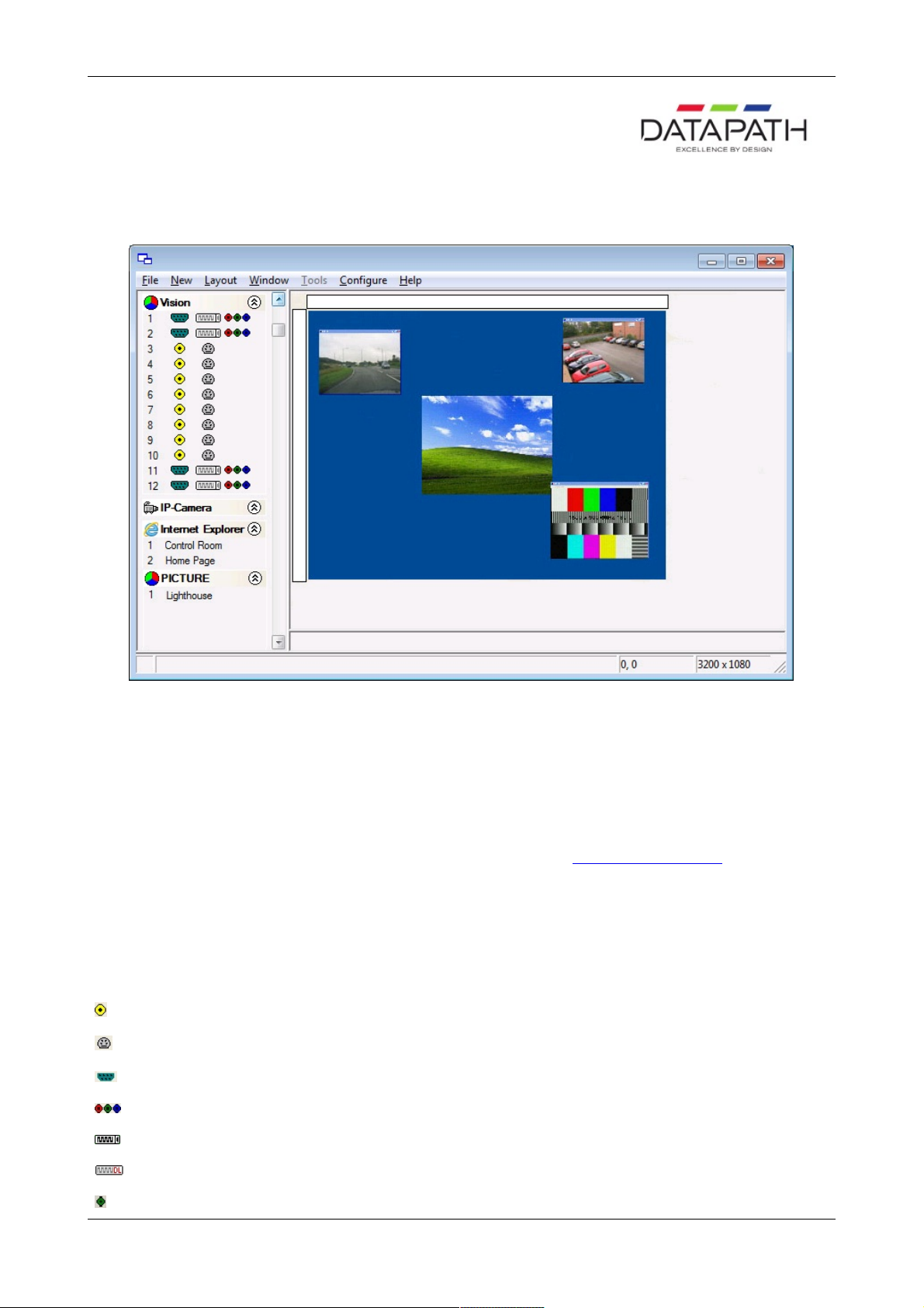
Wall Control-red displays the desktop of the machine that is being controlled. It allows you to remotely display Vision, IPCamera and application windows across a network on another machine or locally on the same machine.
You can use Wall Control-red to interactively move, size and position application windows and control Vision and IP-Camera
windows by using the Windows Properties sheet. Wall Control-red also has a guide and grid function to aid the positioning of
windows.
Wall Control-red allows you to save specific wall layouts as .lay files enabling them to be re-called when required.
Wall Control-red also allows you to save Vision windows as templates called presets. New instances of the saved preset
windows can be created in subsequent layouts. Presets can also be used with the split windows functionality, this allows you to
divide a Vision window into a set of sub-windows, each displaying a cropped portion of the image in the original window.
There is an area of the application around the desktop where windows can be dragged allowing them to be manipulated without
being displayed on the video wall.
Icons Displayed in the Wall Control-red Application Toolbar
The Icons displayed in the application toolbar identify which type of source is available to each input:
= Composite source
= S-Video source
= Analog source
= Component source
= DVI source
= Dual-Link DVI source
= SDI/HD-SDI/3G source
1 / 155
Page 2

= IP Camera source
If an icon has a green surround this indicates the type of source currently being captured for that particular input.
2 / 155
Page 3
Installation
Wall Control-red consists of two separate elements that work together to enable you to control the display wall, the Wall
Control-red Application and the Wall Control-red Server.
Wall Control-red Application
The Wall Control-red Application should be installed on the machine that has been identified to control the display wall. This
could be any machine on the network including the machine driving the display wall. The application element of Wall Control-red
is used to control the position, size and properties of each window displayed on the Server machine.
Wall Control-red Server
The Wall Control-red Server is used to display Vision and application windows. The Server element of Wall Control-red needs
to be installed on the machine from which you wish to create Vision and application windows.
Note:
If you are using the Wall Control-red hardware key for the first time, it should not be inserted into your USB port until
the installation of the application is complete. The operating system will not recognise the device and will allocate a
generic driver.
To install Wall Control-red, browse and locate the INSTALL.EXE, double click on the install icon and the installation wizard will
be activated.
The first dialogue displays details of compatible operating systems. Click Next> to continue and the Licence Agreement
dialogue is displayed. To proceed with the application installation the terms of the License Agreement must be accepted
by clicking on the acceptance box.
Once the Licence Agreement has been accepted click Next>.
Note:
If you are using the Wall Control-red hardware key for the first time, it should not be inserted into your USB
port before you get to this stage of the installation. The operating system will not recognise the device and will
allocate it a generic driver.
The hardware key must remain in the USB port after installation otherwise the advanced Wall Control-red features will not
function.
Wall Control-red will, by default, be installed in Program Files; the Destination dialogue can be used to select a different
location for installation by clicking on Browse… Once the required location has been selected Click Next> to continue.
The next dialogue displays the name of the folder where the Wall Control-red application shortcuts will be created. The
name of the folder can be changed to suit requirements. Click Next> to continue to the Application/Server dialogue.
The Application/Server dialogue enables you to select which elements of Wall Control-red are installed on a particular
machine.
Wall Control-red Server
The Wall Control-red Server is used to display Vision and application windows. It should be installed on the machine that
contains the relevant hardware.
Wall Control-red Application
The Wall Control-red Application is used to control the position, size and properties of each window displayed on the Wall
Control-red Server machine. The Wall Control-red Application should be installed on the machine you wish to use to
control the display. This could be any machine on the network or the same machine as the Wall Control-red Server. Click
Next> to continue to the Components dialogue.
Use the Components dialogue to select which components of Wall Control-red you wish to install. Click Next> to
continue to the Install dialogue.
The Install dialogue displays a summary of the options you have selected during installation. If you wish to change any of
the options, use the <Back button and locate the option you wish to change. Once the correct options have been
selected, click Next> to install Wall Control-red.
Wall Control-red has now been installed; Click Finish and a prompt to reboot your machine will be displayed.
3 / 155
Page 4

4 / 155
Page 5
Hardware Compatibility
Wall Control-red is designed for use with the following hardware:
ImageDP4
Image4
VisionRGB-X2
VisionRGB-E1
VisionRGB-E2
VisionSD8
VisionSD4+1
VisionDVI-DL
VisionSDI2
ImageDP4
ImageDP4 operates under Windows® Vista/XP/7 and spreads the Windows desktop across the multi-screen display. Both
portrait and landscape display configurations are supported. Ideal for video wall and digital signage applications.
For information on how to correctly install and set up the card, refer to the User Manual
Image4
Image4 operates under Windows® Vista/XP/7 and spreads the Windows desktop across the multi-screen display. Both portrait
and landscape display configurations are supported. Ideal for video wall and digital signage applications.
For information on how to correctly install and set up the card, refer to the User Manual
VisionRGB-E1
The VisionRGB-E1 is a PCI-e x4 low profile single channel capture card. It displays the output from one video source as a
window on the desktop of your PC.
Wall Control-red is able to launch, configure, format the input sources and also move and re-size the Vision window on the
display wall. For information on how to correctly install the card, refer to the User Manual.
VisionRGB-E2
The VisionRGB-E2 is a PCI-e x4 dual channel capture card. It displays the outputs from two video sources as windows on the
desktop of your PC.
Wall Control-red is able to launch, configure, format the input sources and also move and re-size the Vision window on the
display wall. For information on how to correctly install the card, refer to the User Manual.
VisionSDI2
The VisionSDI2 is a PCI-e x4 dual channel Serial Digital Interface capture card that supports SD-SDI, HD-SDI and 3G-SDI.
The VisionSDI2 is able to launch, configure, format the input sources and also move and resize the Vision window on the
5 / 155
Page 6

display wall. For information on how to correctly install the card, refer to the User Manual.
VisionRGB-X2
The VisionRGB-X2 is a powerful analog capture card for the desktop PC. It displays the output from two video sources as
windows on the desktop of your PC. Two separate analog data sources can be connected simultaneously with the ability to
switch between them quickly and easily.
Wall Control-red is able to launch, configure, format the input sources and also move and re-size the Vision window on the
display wall. For information on how to correctly install the card, refer to the User Manual.
VisionSD8
The VisionSD8 is a PCI-e x4 eight channel video capture card. It displays the output from one video source as a window on the
desktop of your PC.
Wall Control-red is able to launch, configure, format the input sources and also move and re-size the Vision window on the
display wall. For information on how to correctly install the card, refer to the User Manual.
VisionSD4+1
The VisionSD4+1 is a PCI-e x4 four channel video capture card and a single channel RGB,DVI capture card. It displays the
outputs from two video sources as windows on the desktop of your PC.
Wall Control-red is able to launch, configure, format the input sources and also move and re-size the Vision window on the
display wall. For information on how to correctly install the card, refer to the User Manual.
VisionDVI-DL
The VisionDVI-DL is a PCI-e x4 single channel Dual-Link DVI capture card. It displays a single dual link video source on the
desktop of your PC.
Wall Control-red is able to launch, configure, format the input sources and also move and re-size the Vision window on the
display wall. For information on how to correctly install the card, refer to the User Manual.
6 / 155
Page 7
IP-Camera
Wall Control-red is designed to allow you to view IP-Camera streams that use compatible network protocols 1. Wall Control-red
is pre-configured for use with a list of recommended IP-Camera sources.
Axis 210
Axis 233D Network Dome
Axis Q4701 Encoder
Bosch NWC-0455 Dinion
Bosch VideoJet X10
Bosch VideoJet X20
Bosch VIP X1600 XFM4
Bosch VIP X1600 M4SA
Mitsubishi NM-C130FD
Moxa VPort 354 Video Encoder – 1
Moxa VPort 354 Video Encoder – 2
Moxa VPort 354 Video Encoder – 3
Moxa VPort 354 Video Encoder – 4
Panasonic WV-NP304
Axis 233D Network Dome
Axis Q4701 Encoder
Siqura encoder S60E - MPEG4
Siqura encoder S60E - H.264
Siqura HD62 - MPEG4
Siqura HD62 - H.264
TEST MODEL
Test Model
The Test Model is a default installed on the Render Station to enable the user to test the connectivity to the Render Station. For
instructions on configuring the Test Model see Troubleshooting.
Wall Control-red can also be configured to support other models of IP-Camera, including those from additional manufacturers
2
.
Before any IP-Camera windows can be opened the user must add and configure one or more Render Stations 2. Render
Stations display outputs must be connected using DVI cables to a VisionRGB-E2 contained in the Wall Control-red server. The
outputs from the Render Station are captured and displayed using the VisionRGB-E2 hardware. VisionRGB-E2 cards assigned
to the capture of Render Stations are no longer available as Vision inputs.
Once the Render Station has been configured the cameras can be added via the IP-Camera option on the Configure menu 2.
The process of configuring cameras involves choosing the manufacturer and model of the IP-Camera, along with its network IP
address or host name.
Notes:
1. Real Time Streaming Protocol (RTSP)
2. Dependent on the type of Wall Control-red Licence purchased
7 / 155
Page 8

8 / 155
Page 9

Networking
If you intend to allow access to your Wall Control-red Server across a network you will need to:
Decide on a security policy for the connections.
Configure Wall Control-red.
Configure your Operating System.
9 / 155
Page 10
Security Policy
In order for a user to connect to a Wall Control-red server, the server must be listening on at least one port. These ports have a
potential vulnerability. If your server is working in a secure environment, you probably don’t need to worry about unauthorised
access to the ports. If your Wall Control-red server is on a network that is generally accessible, you will probably want to restrict
access to the ports.
By default, Wall Control-red will require that users who connect to a port on the Wall Control-red server provide a user name
and a password. The user name and password must correspond to an account on the Wall Control-red server or if the Wall
Control-red server is participating in a domain, an account on the domain.
To access the Wall Control-red Administrator dialogue select:
Start/All Programs/Wall Control-red/ Wall Control-red Administrator
Note: To use the administrative dialogue you must be a member of the Administrator Group.
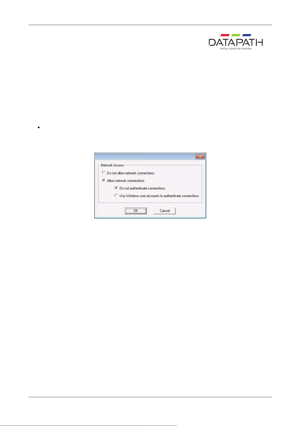
Use the dialogue to select the level of security you require, if, as stated above, your Wall Control-red server is working in a
secure environment then you may wish to allow network connections without the need to authenticate.
If the Wall Control-red server is on a generally accessible network then you may wish to select the Use Windows user
accounts to authenticate connections option.
Once Network Access has been determined, click on OK and re-boot for the changes to be applied.
You must be a member of the Administrator group to run the Wall Control-red Administrator program.
10 / 155
Page 11

Operating System Configuration
Wall Control-red works with the following Operating Systems:
Windows® XP and Windows® XP Service Pack 1
Windows® XP Service Pack 2
Windows® Server 2003/2008
Windows® 7
11 / 155
Page 12
Windows® 7
If the Wall Control-red server is not participating in a domain, you will need to change the Inbound Rules.
Prior to carrying out this procedure, ensure that a network cable is plugged in to your machine.
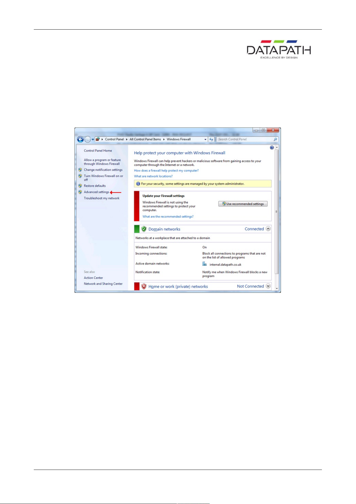
Open the Control Panel and click on Windows ® Firewall, the following dialogue is displayed:
Click on Advanced settings to open the Advanced Setting dialogue.
12 / 155
Page 13
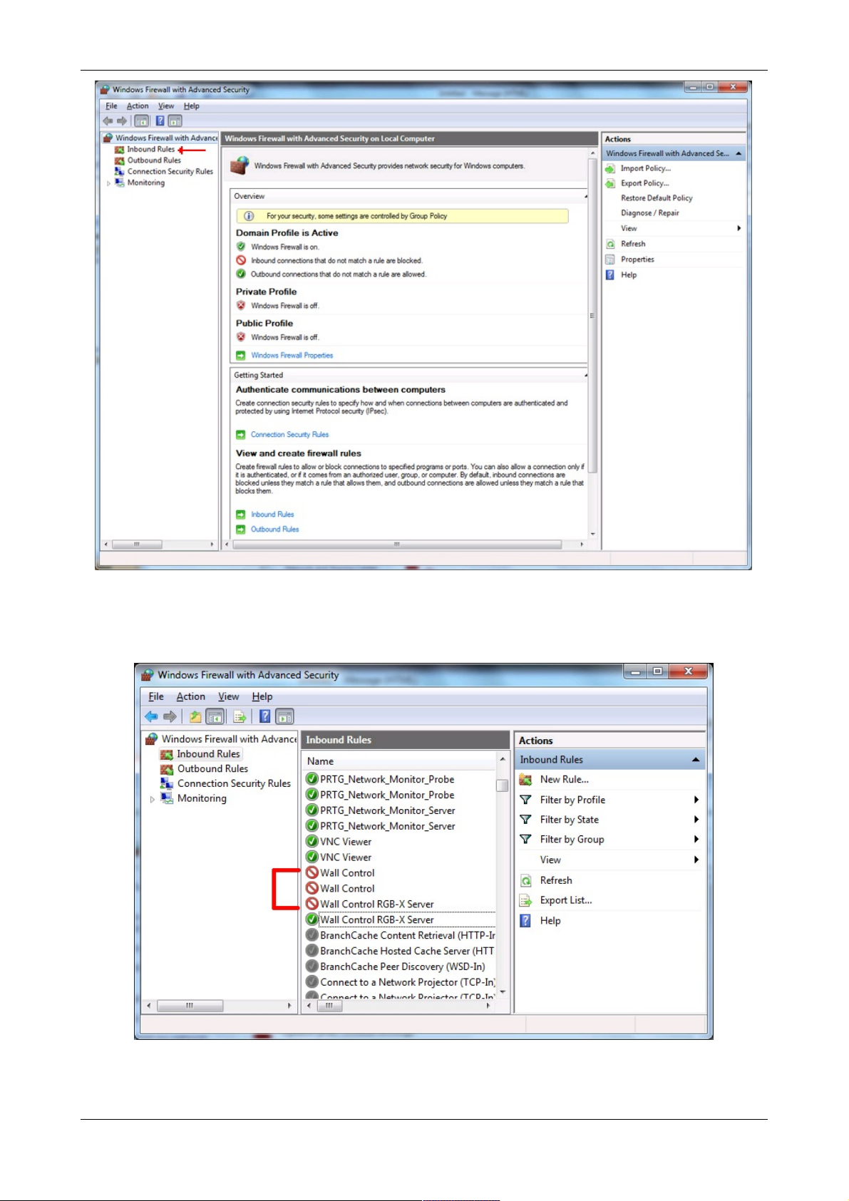
Click on Inbound Rules to open the Inbound Rules dialogue:
Locate all Wall Control-red settings and ensure each one is active (has a green icon). The Profile should = Domain, Enabled
should = Yes and Action should = Allow.
13 / 155
Page 14
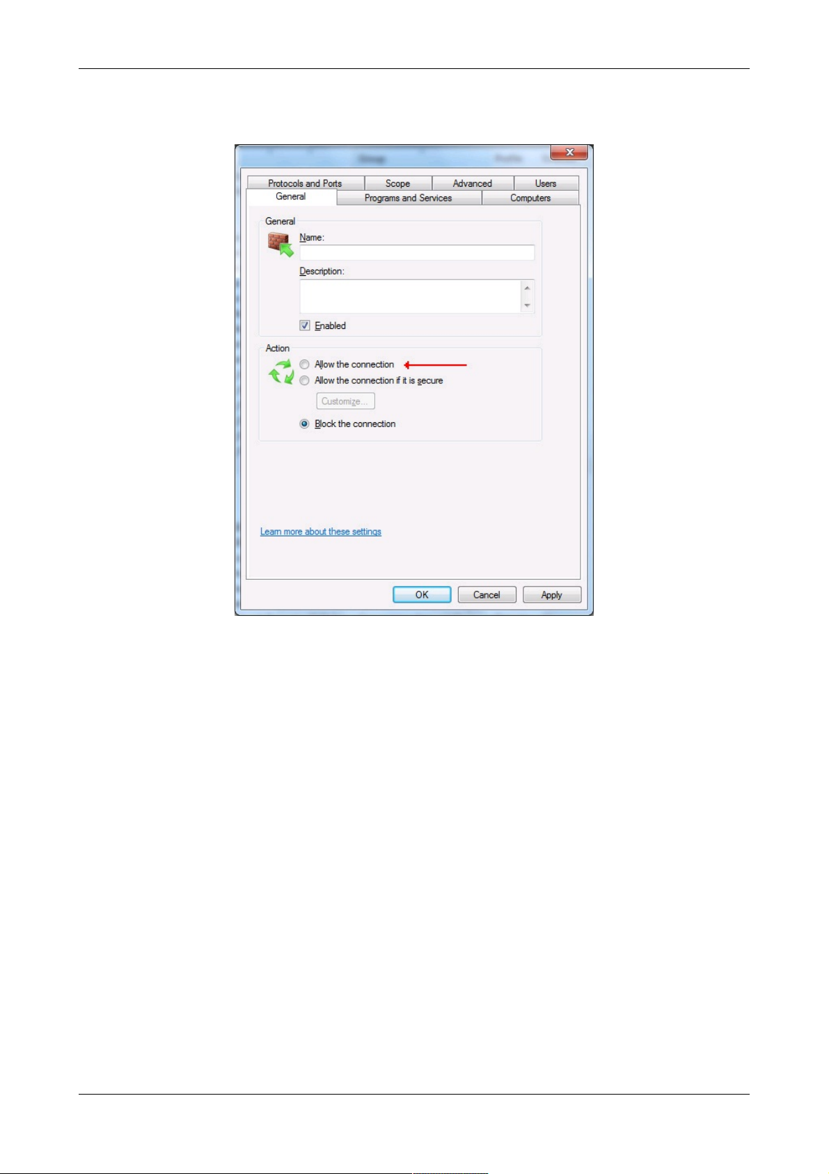
To unblock or allow a broken connection, double click on the specific Inbound rule to open the Properties dialogue and on the
General tab select Allow the connection and click on Apply as shown in the following dialogue:
Once all the Inbound Rules have been established, ensure the Network cable is plugged into your machine and then re-install
Wall Control-red
14 / 155
Page 15

Windows® XP and Windows® XP Service Pack 1
If the Wall Control-red server is not participating in a domain, you will need to change the way network logons that use local
accounts are authenticated. Network Authentication.
15 / 155
Page 16

Windows XP® Service Pack 2 and Windows Server® 2003/2008
Network Logons
If the Wall Control-red server is not participating in a domain, you will need to change the way network logons that use local
accounts are authenticated. Network Authentication.
If password protection is enabled, accounts for users must have passwords.
Blocking
If Wall Control-red is installed on Windows XP® Service Pack 2 or Windows Server® 2003 the install program automatically
configures the firewall.
The firewall needs to be configured manually if you upgrade to Windows XP® Service Pack 2 after Wall Control-red has been
installed.
As each component of Wall Control-red tries to access the network, the firewall will display a dialogue:
Select the Unblock option in each dialogue to allow Wall Control-red to work correctly.
Changes made take effect immediately.
Components that must access the network are:
wallctl
rgbxsvr
appsvr
ipcamsvr
16 / 155
Page 17
Network Authentication
If a Windows XP® machine is not participating in a domain, there are two ways it can treat network connections:
Classic - local users authenticate as themselves.
Guest only - local users authenticate as Guest.
The default configuration is Guest only - local users authenticate as Guest.
In order for Wall Control-red to be able to authenticate users, your system must use Classic - local users authenticate as
themselves.
For more information, search for Network Access: Sharing and security model for local accounts in Windows XP® Help
and Support.
To change the configuration to Classic - local users authenticate as themselves.
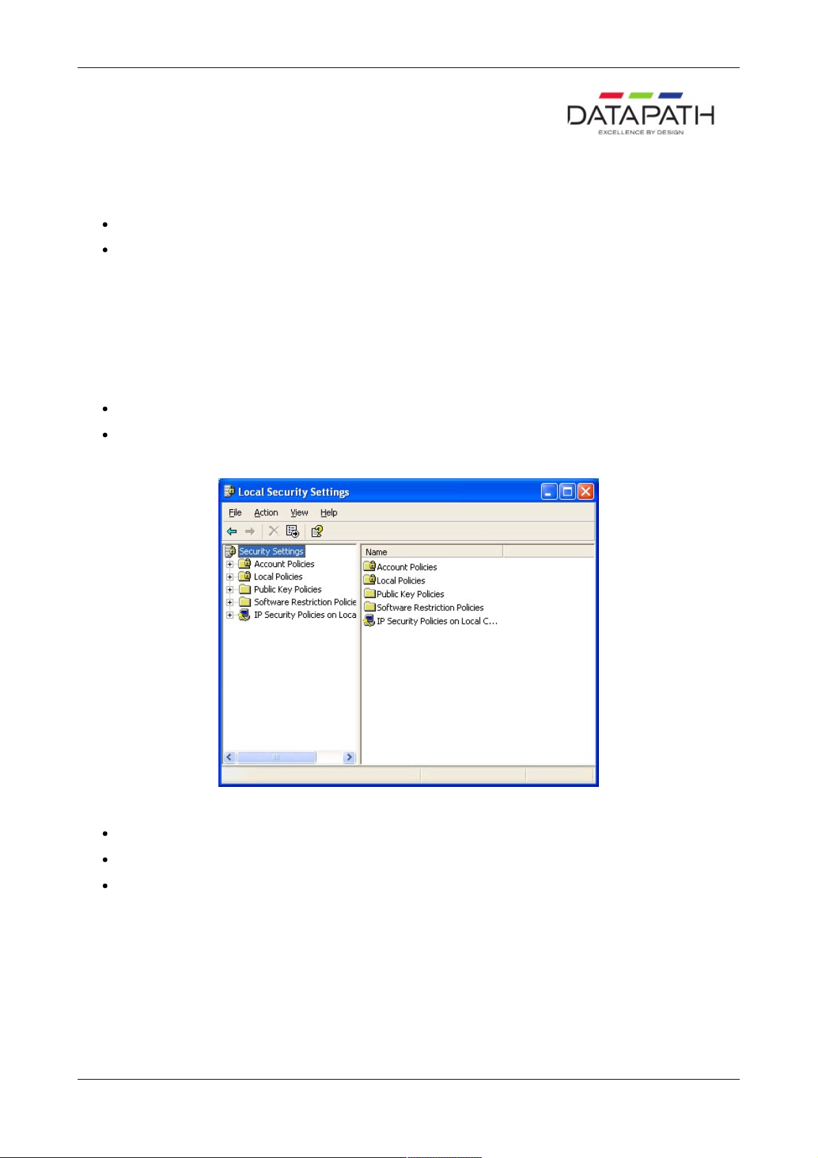
Open Control Panel in Classic View and select Administrative Tools.
Select Local Security Policy and the following dialogue is displayed:
Expand Local Policies in the left panel.
Select Security Options.
Scroll down the options and locate Network access: Sharing and security model for local accounts as shown below:
17 / 155
Page 18
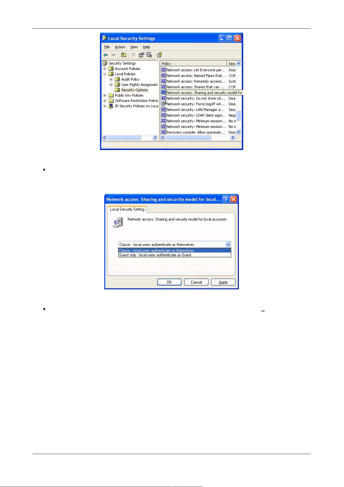
Double click on the Network access: Sharing and security model for local accounts string and the following dialogue
is displayed:
Select Classic - local users authenticate as themselves from the dropdown menu and click on Apply then OK.
18 / 155
Page 19
Running the Wall Control-red Application
How to Launch the Wall Control-red Application
Connect to a Wall Control-red Server
Creating Windows
Moving Windows
Changing Window Properties
Saving a Layout
Loading Layout File
Saving a window as a Preset
How to Launch the Wall Control-red Application
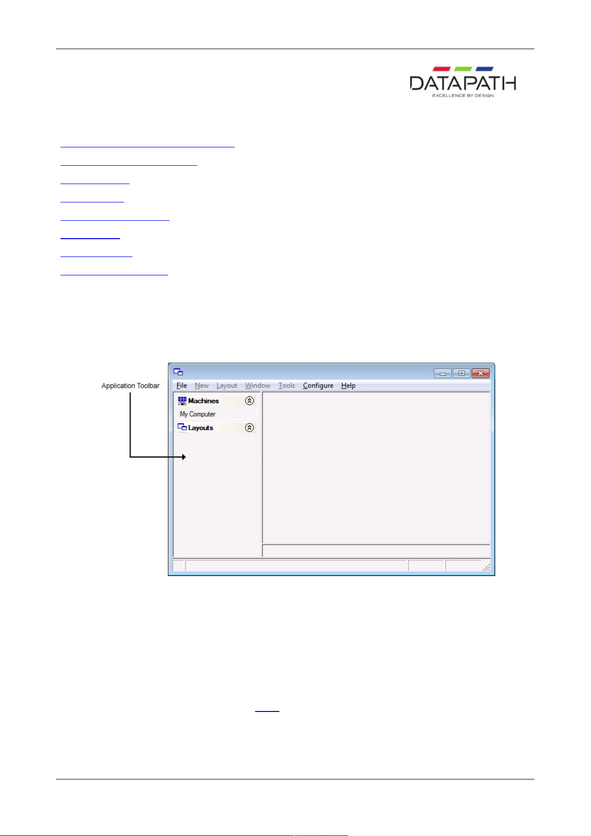
Click on the Windows Start button and select All Programs/Wall Control-red. From the Wall Control-red menu, select Wall
Control-red and the following dialogue is displayed:
Connect to a Wall Control-red Server
If the Wall Control-red application and Wall Control-red server are installed on the same machine then select Wall Control-red
– My Computer from the programs menu, alternatively, double click My Computer in the Machines list on the Wall Control-
red application Toolbar.
The Machines list shows the Wall Control-red Servers that have previously been connected to.
The Layouts list shows the most recently used layout files. Double click to open the selected file.
Details of how to connect to the server can be found HERE .
Creating Windows
Once a connection to the server has been established then windows can be created for display.
Windows can be created using the New menu or the application Toolbar.
19 / 155
Page 20
By using the New menu the following windows can be created and displayed:
Vision - A Vision output can be displayed if a Vision card is installed
Preset - A preset window can be displayed providing a Vision card is installed in the system and one or more Vision
windows have been saved as presets.
Application – Windows based applications can be opened and displayed eg. VNC Viewer, Picture.exe, Microsoft
Powerpoint, DGCPlay.
Select Wall Control-red from the Configure menu to capture the desktop and display in the Wall Control-red application
window.
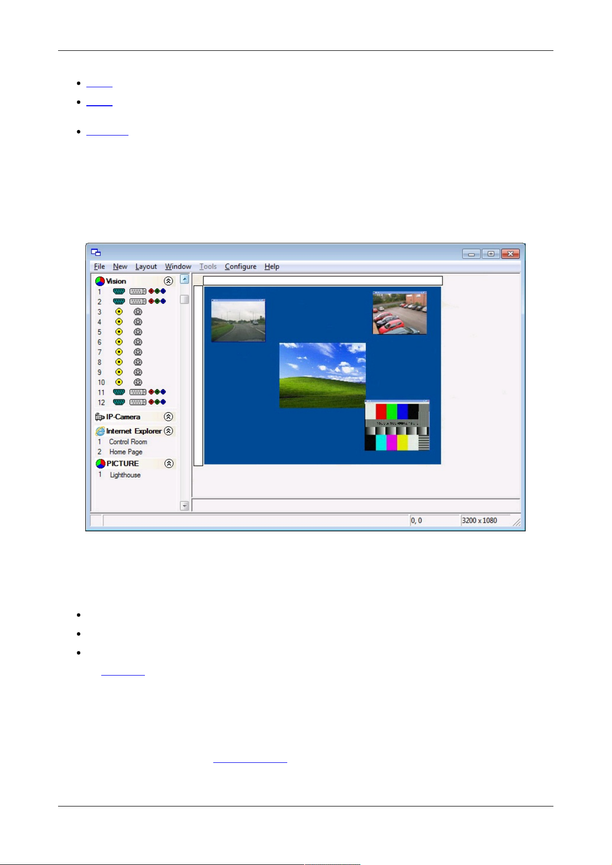
Using the Wall Control-red application Toolbar, you can select a particular device or input:
The application Toolbar displays a list of the type of windows that can be opened, depending on the hardware you have
installed in your machine. Use the drop down menus to select the required inputs for display.
To open the required inputs:
Select the required input using the cursor and drag to a preferred position on the wall.
Double click on the required input and the window will open, positioned at the top left of the display wall.
Open multiple inputs by pressing the shift key and clicking the required number of inputs with the mouse.
Using the Define Grid function, the widows can be placed in a specific position using a 3-pixel width snap-to-grid functionality.
Moving Windows Around the Display Wall
Setting up a video wall requires windows to be moved on the desktop. All types of window can be moved in the same way.
Using the Window Properties
Windows can also be moved using the Window Properties dialogue. Using the Position controls Top and Left the windows
can be placed anywhere on the display wall.
Using the Mouse
20 / 155
Page 21

Use the mouse to select the window in the Wall Control-red application; by keeping the left mouse button pressed, the window
can be dragged to any preferred position on the wall. Used in conjunction with Grids and Guides, the window can be placed in
an exact position.
Again, by using the mouse, right click over the window in the Wall Control-red application and select Move. This allows you to
move the window around the display wall without depressing the mouse button. To release the window in a preferred position,
click the left mouse button.
Changing Window Properties
The properties of a window can be changed using the Windows Properties, Input Settings and On Screen Display
Properties dialogs.
The Window Properties allow you to change the position of the window, the size and aspect ratio, the style, caption title and the
window ID.
The Input Settings allow you to change the appearance of a Wall Control-red inputs using the Input, Cropping and Display
setting controls.
The On Screen Display Properties allows you to configure the display type, text and font details of the on screen display.
Saving a Layout
When your display wall has been configured i.e. all the required windows have been opened and positioned, you may wish to
save the layout. Wall Control-red allows you to save the layout as a .lay file and store it on your machine for future use.
To save a layout use the File menu on the Wall Control-red Application and select Save or Save As..
Only the full version of Wall Control-red allows you to save layout files.
Loading Layout Files
To load a saved layout file:
File Menu
With the Wall Control-red application open, select the File menu and then Open… You will be asked if you wish to save the
changes you have made. Browse to the layout file you wish to load and select Open. The layout will be opened and the
windows positioned on the display wall.
Saving a Window as a Preset
Once a window has been configured and the window properties and cropping have been set, the window can be saved as a
preset. The presets are saved with a .WCP file extension in a folder called Preset Windows inside the directory where Wall
Control-red Server was installed.
To save an Vision window as a preset, select a displayed Vision window and then select Save as Preset from the Window
menu. Alternatively, right click on the Vision window and select Save as Preset .
21 / 155
Page 22

Menu Options
The Wall Control-red Application has six menu options:
File
New
Layout
Window
Tools
Configure
Help
22 / 155
Page 23

File Menu
The File menu allows you to manage layout files and connections.
New
Opens a new (empty) layout file.
Open
Opens an existing layout file.
Save
Saves the current layout.
Save As
Saves a layout with a specific name and location.
Connect
Connects the application to a specific machine.
Disconnect
Closes the current connection
Most recently used files
List of the most recently used layout files. Selecting one of these files opens it.
Exit
Closes the application.
23 / 155
Page 24

New
When New is selected:
A prompt is displayed asking if any changes to the current layout are to be saved.
If changes are to be saved, click Yes and follow the steps detailed in Save/Save As
If changes are not required to be saved click No
The windows on the machine close.
The image of the desktop from the machine will continue to be displayed.
The New option is only available when connected to a machine.
24 / 155
Page 25
Open
When Open is selected:
A prompt is displayed asking if any changes are to be saved.
Browse to the layout file to be opened.
When a layout file has been located and selected, the following takes place:
If a current active connection is being used and the selected layout file is for a different computer, the following dialogue is
displayed.
Select Cancel and the operation is terminated.
Select OK:
If Close Windows is selected, all windows are closed and the connection is terminated.
Previously Saved Layouts
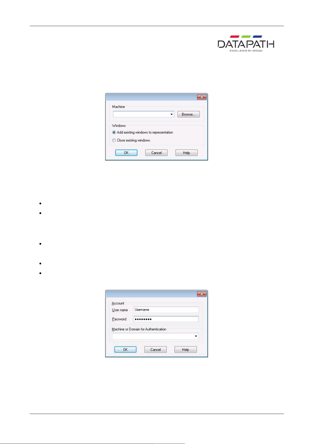
When opening a previously saved layout the following dialogue will be displayed should an error occur:
The dialogue displays details of any errors found by the application when opening a layout.
Use the up/down arrows to scroll through the displayed text.
Click on the Save As… button to save the information as a text file for later use or to assist in support queries.
25 / 155
Page 26

Save/Save As
Save:
Select Save to save the current layout.
If the layout has not been previously saved, i.e. it is a new layout then the Save As dialogue is displayed.
Browse to the folder where the layout is to be saved, enter a File name and click on Save.
Save As:
Select Save As to save a layout with a specific name to a particular location using the displayed dialogue.
Note: This function is only available if there is an active connection.
26 / 155
Page 27
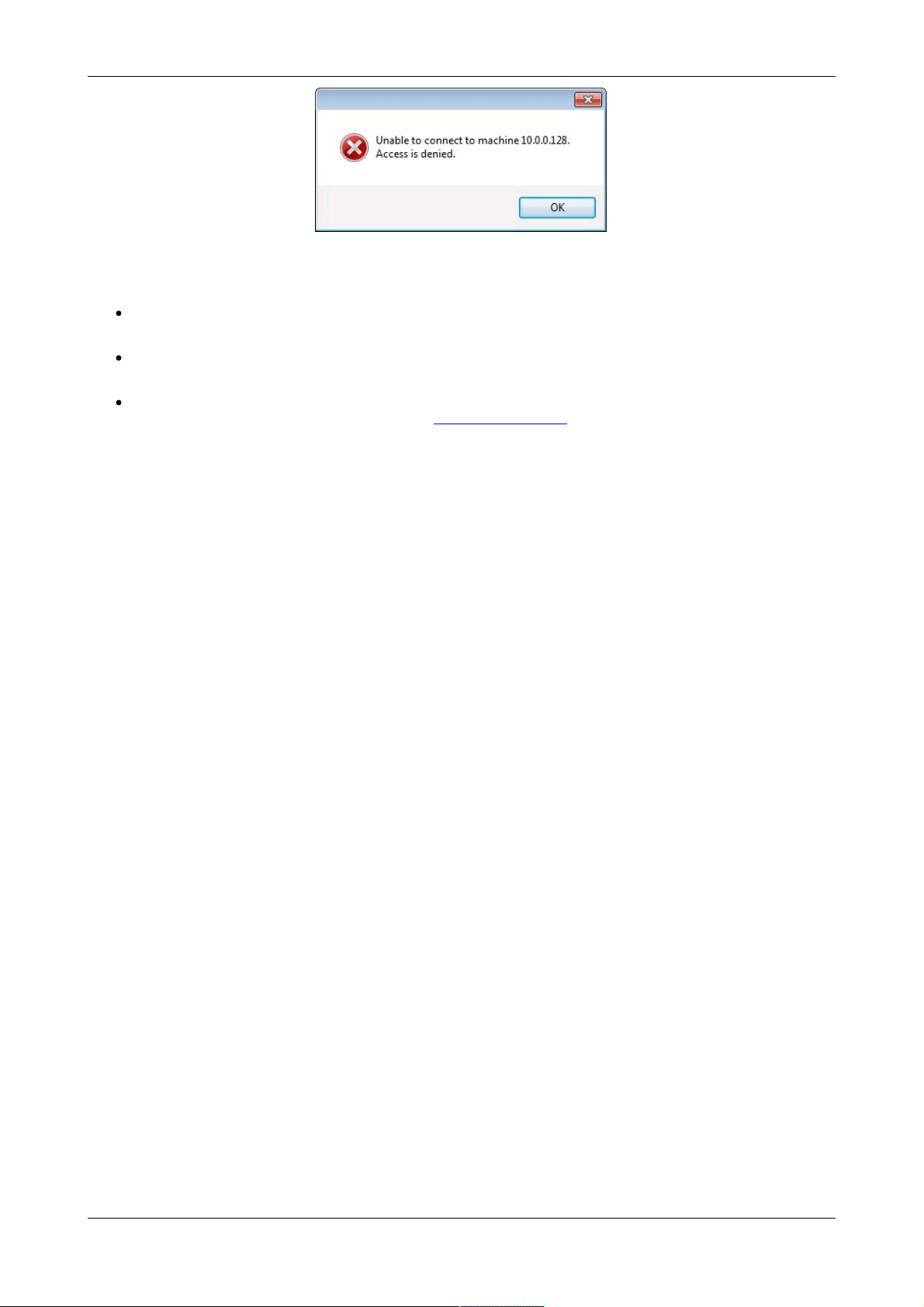
Connect
Select Connect and the following dialogue is displayed:
Use this dialogue to specify which machine is to be controlled using the Wall Control-red application
Use the drop down arrow to display a list of the most recently selected machines; the list will include My Computer which can
be used to connect to the machine where the Wall Control-red application is running.
The machine can be specified by name or by IP address.
Select Browse… to locate a machine on the local network.
Windows
Add existing windows to representation:
Displays the open windows.
Close existing windows:
Will close all Wall Control-red managed windows.
Click on OK to connect to the selected machine.
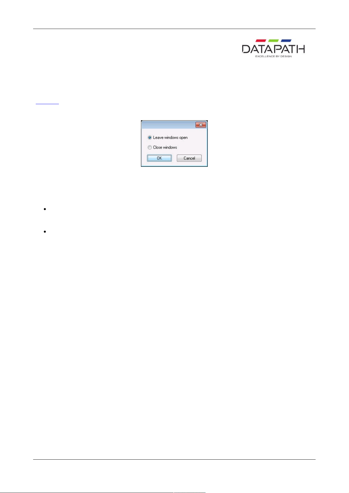
If you connect to a machine that has been configured to authenticate connections, you will be required to provide a user name
and password. The user name and password must be for an account machine you are connecting to or on the domain if the
machine is part of a domain.
27 / 155
Page 28
If the above error message is displayed one of the following problems has occurred:
The user name, the password or the machine/domain that you have entered are not correct. Try entering the details
again.
If the machine to which you are connecting is running Windows XP® Service Pack 2 and you have not entered a
password, you will need to change your account so that you have a password.
If the machine you are connecting to is running Windows XP® and it is not participating in a domain, you will need to
change the Network Logon settings on the machine. Network Authentication.
You can create a shortcut on your desktop that specifies the machine and your user name. When you double click on this
shortcut, it will take you straight to the Logon dialogue for you to enter your password.
28 / 155
Page 29
Disconnect
This option is only available when a connection is active.
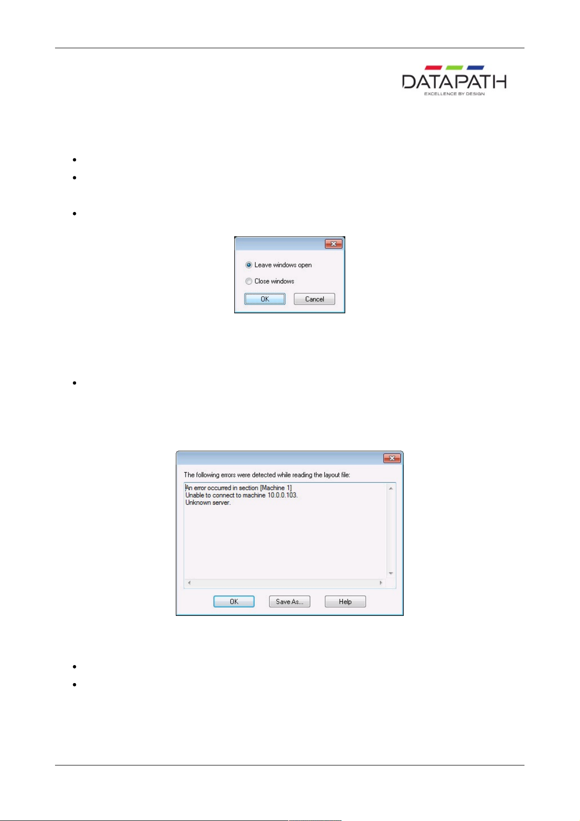
When Disconnect is selected, the following dialogue may be displayed, depending on how Wall Control-red has been
configured.
The dialogue offers two selections.
Leave windows open:
Leaves open all windows that Wall Control-red manages.
Close windows:
Closes all windows that Wall Control-red manages.
If any changes to the layout have been made a Save prompt will be displayed.
29 / 155
Page 30

Recent Files
Most Recently Used File List:
The File Menu contains a section where the six most recently used files are displayed, the most recent at the top of the list. By
selecting a particular file, the layout is re-loaded.
To select a file simply click on it or press the corresponding number on your keyboard.
If a file is selected that no longer exists then the file name will be automatically deleted.
30 / 155
Page 31

Exit
Select Exit to close the application.
31 / 155
Page 32

New Menu
The New Menu displays options for each window category.
Preset Windows
Opens a new Preset Window
Vision Window
Opens a new Vision Window
IP-Camera Window
Opens a new IP-Camera window
Run Application
Opens the Run Application dialogue
32 / 155
Page 33

Preset Windows
When Preset Window… is selected from the NewMenu the following dialogue is displayed:
The New Preset Windows option will not be available unless a Vision card is installed and preset windows have been
previously saved.
Use the drop down list to select the preferred Preset Window and click on OK. A Vision window with the same window settings,
input properties and on screen display that was saved as a preset is created and displayed in the top left of the display.
33 / 155
Page 34

Vision Window
When Vision Window… is selected from the NewMenu the following dialogue is displayed:
Use the drop down list to select the preferred Vision input and click on OK.
34 / 155
Page 35

IP-Camera Window
When IP-Camera Window… is selected from the New menu then one of two actions will occur. If no IP-Cameras have been
configured then the following message is displayed.
Select Yes to display the IP-Camera configuration dialogue where you will be able to add and configure new IP-Cameras for
use in Wall Control-red.
If one or more IP-Cameras have been configured, the following dialogue is displayed.
Use the drop down list to select the preferred IP-Camera window and click OK.
35 / 155
Page 36

Run Application
When Run Application… is selected from the New menu the Run Application dialogue is displayed. The dialogue has two
tabs, Application and Application Input.
Application
Application
The full path of the Application executable must be specified.
You can select the Application as follows:
Use the drop down list to select a configured Application to run.
Click on the Browse button to select a new Application
Type in the full path of the Application executable
Command line
Use the Command line edit box to specify parameters for the Application. Many Applications accept the name of a file to be
opened. For details of command line arguments, refer to your Application documentation.
Start in folder
The Start in folder is the folder in which the Application is run.
If a Start in folder is not specified, the application will run in the folder in which it resides.
With Run Application, Wall Control-red can launch any application. Unfortunately, each application works in its own way so the
exact outcome when you launch an application varies.
Application Command Line
The Command Line window displays the full Command Line that will be passed to the Wall Control-red.
Application Input
36 / 155
Page 37

The Application Input dialogue allows the user to identify and select Applications created in the Configure Application
dialogueue.
Application
Use the Application drop down list to select the required Application. The list will only display those Applications that have been
configured on the system.
Input
When the Application has been selected, use the Input drop down list to select the required input associated with the
Application.
Switches
Once the Application and input have been selected the Switches edit box is automatically populated with the switches for that
specific application.
Path
Once the Application and input have been selected the Path edit box is automatically populated with the path to the application.
Command Line
The command line window displays the resulting command from the switches and path edit boxes. The command is executed
by clicking the Run button.
A new input can be created by editing the Input drop down list. Type in the name of the new input and edit the path or browse to
a new file in the Path edit box. By clicking on the Run and Save button the new input will run and be saved on the system. The
new input with be displayed in the input window on the Configure Application dialogueue.
This dialogueue cannot be used to modify and save an existing input.
Any modifications to the Switches edit box will result in the Run and Save button being disabled irrespective of other changes
made to any other controls on this dialogueue.
37 / 155
Page 38

DGCPlay
DGCPlay is a utility that will play movie files including WMV, MPEG, and AVI depending on the codecs installed on the system.
Some media will require additional codecs not installed as standard components of Windows.
To activate the DGCPlay application open Run Application from the New Menu by specifying Dgcplay.exe as the target followed
by the command line options separated by spaces. The Dgcplay.exe will be located in the Wall Control-red folder
Command Line Options
Nomenclature
Italic - Information that you must supply.
Bold - Elements that you must type exactly as shown.
Ellipsis (...) - Parameter that can be repeated several times in a command line.
Between brackets ([]) - Optional items.
Between braces ({}) - Set of choices (separated by I) from which you must choose only one.
Courier font - Code or program output.
–path=media file path
-Window=[left],[top],[width],[height]
Change the position and size of the window.
All the values are optional but the commas must be used.
-WindowStyle={BorderAndTitleBar|BorderOnly|NoBorderOrTitleBar}
-repeat={Yes|No}
38 / 155
Page 39

Picture.exe
Picture.exe is a utility that is used to display static pictures in any format supported by Windows® i.e. BMP, JPG, PNG etc
To activate the Picture application open Run Application from the New Menu by specifying picture.exe as the target followed by
the command line options separated by spaces. The picture.exe will be located in the Wall Control-red folder
Command Line
In the Run Application dialogue:
In the Application box put the full path of the Picture application.
For example:
C:\Program Files (x86)\Wall Control\picture.exe
In the Command Line box put the full path of the file. For example:
–file=”C:\Users\Public\Pictures\Sample Pictures\koala.jpg” –xpos=0 –ypos=0 –width=2800
–height=2100 –caption=”Title Bar Caption”
If the file name or path contains spaces, enclose the path in quotes.
-file = name of the file to display
-xpos|-ypos = number
To define the position of the top left corner
-width|-height = number
To define the size of the window
-caption = text
Enter text for the description in the Title Bar. By default the picture is displayed without a border or title bar
39 / 155
Page 40

RealVNC Viewer
When you run RealVNC Viewer it will display a dialogue asking you for a RealVNC server and then display another dialogue for
a password for that server. You may not be able to respond to these dialogues.
Once a connection has been made using RealVNC Viewer, you can save the connection details to a configuration file. The
configuration file can be specified on the command line allowing RealVNC Viewer to run without displaying any dialogues.
Saving the Configuration File:
Connect to the machine you wish to view with RealVNC Viewer.
Click on the icon at left end of the title bar to display the menu.
Select Save connection info as…
Choose a file name and a folder and click on Save.
You will be asked Do you want to save the password to this file? Click on Yes.
Using the Configuration File
In the Run Application dialogue:
In the Application box put the full path of the RealVNC viewer application.
For example:
C:\Program Files\RealVNC\vncviewer.exe
In the Command Line box put /config followed by the full path of the configuration file. For example:
/config "C:\Documents and Settings\User\ My Documents\file.vnc"
If the configuration file name or path contains spaces, enclose the path in quotes.
40 / 155
Page 41

Microsoft PowerPoint®
To open a PowerPoint presentation as a slide show use the following command line:
/s "C:\Documents and Settings\User\My Documents\presentation.ppt"
If the presentation file name or path contains spaces, enclose the path in quotes.
For a slide show to continue cycling through the slides, the PowerPoint window must be the active window.
Only one PowerPoint application can be running at a time. If you try to start PowerPoint while it is already running, the second
PowerPoint sends a message to the first and then exits.
When a layout file is opened, Wall Control-red closes the windows and applications it is responsible for and then creates the
windows specified in the layout file. The windows and applications are sent messages to close them. The PowerPoint
application is run to create a PowerPoint window.
If the existing PowerPoint application has not finished closing by the time Wall Control-red tries to open the new presentation, it
is possible that a message to open a new PowerPoint presentation and a message to close are sent to the existing PowerPoint
application. The result is that PowerPoint closes.
41 / 155
Page 42

Layout Menu
The Layout Menu enables you to create grids, rulers and guides in the Wall Control-red application.
Create Guide
Define Grid
Clear Guide
Clear all Guides
Snap Sensitivity
42 / 155
Page 43

Create Guide
Select the Create Guide option and the following dialogue is displayed:
Select the Orientation, either horizontal or vertical. Use the up/down arrows to adjust the position of the guide i.e. the number
of pixels from the top for vertical or left for horizontal then click on OK. A guide is then created at the specified position.
You can also create a guide by clicking on one of the rulers.
43 / 155
Page 44

Define Grid
Using the Define Grid option, a grid may be placed over the representation to assist in the positioning of windows. The grid
has a three pixel snap-to-grid functionality.
Using the up and down arrows, select the size of grid required.
Pixels
The grid can be defined by pixel size i.e. 150 x 150 pixels.
Divisions of a desktop
This option will divide the desktop into equal sized rectangles depending on the number of divisions selected.
When the correct grid spacing has been selected, click on OK and a grid will be displayed in the representation window.
To re-set a defined grid you must first select the Clear all Guides option otherwise the previous grid will remain displayed.
44 / 155
Page 45

Clear Guide
Right click on a guide in the ruler and select this option to clear the guide.
45 / 155
Page 46

Clear all Guides
The Clear All Guides option removes all guides from the Wall Control-red application window.
46 / 155
Page 47

Snap Sensitivity
The snap sensitivity dialogue allows you to customize the sensitivity of the snap-to-grid functionality for the current connection.
The sensitivity value effects the distance that representation windows need to be moved in order to snap to the nearest guide.
The closer the sensitivity is to the maximum value 10 then the stronger the snap effect will be.
47 / 155
Page 48

Window Menu
The options contained in the Window menu will not be activated unless windows are displayed in the application.
Window Properties
Input Settings
Carousel Settings
On Screen Display
Split into Sub-Windows
1
Audio Settings
Restore
Move
Size
Minimise
Maximise
Close
Windows
1. The Split into Sub-Windows function only applies to Vision windows.
48 / 155
Page 49

Restore
This option restores the current window. This option is only available when the window is minimised or maximised.
49 / 155
Page 50

Move
The selected window can be moved using the keyboard interface of the representation. This option is not available when the
window is minimised or maximised.
50 / 155
Page 51

Size
The size of the selected window can be changed using the keyboard interface of the representation. This option is not available
when the window is minimised or maximised.
51 / 155
Page 52

Minimise and Maximise
Minimise
Selecting this option minimises the selected window and an icon representing the minimised window is displayed in the bottom
left corner of the representation.
Maximise
Selecting this option maximises the window across the desktop of the target machine.
52 / 155
Page 53

Close
Select this option to close the selected window.
53 / 155
Page 54

Windows
Selecting Windows… from the Windows Menu displays the following dialogue:
The Windows dialogue displays a list of the windows being controlled by the Wall Control-red application.
If you click on a single window in the list, you can activate or close the window using the buttons.
If you click on multiple windows with the Ctrl key held down, you could close the selected windows by clicking on the Close
button.
Click on OK to close this dialogue.
54 / 155
Page 55

Window Properties
Selecting Window Properties from the Window Menu will display a properties dialogue box relevant to the type of window
currently active:
Vision Properties
Application Properties
IP-Camera Properties
55 / 155
Page 56

Vision Window Properties
The Vision Window Properties sheet enables you to change the appearance of the Vision window. When the required changes
have been entered, click on OK for the changes to take effect.
Select "Window Properties" with a Vision Window activated and the following dialogue is displayed.
The Vision Window Properties dialogue has the following groups:
Position
Size
Aspect Ratio
Style
Cursor
Window ID
Caption
Invalid Input
Capture Format
Deinterlace
56 / 155
Page 57

Transfer Data
Scaling
Capture Rate
Position
The position of the selected Vision window can be adjusted to suit your requirements.
Top and Left
Using the up and down arrows the selected Vision window can be positioned anywhere on the desktop. The values are in
pixels. The value Top = 0 and Left = 0 will position the Vision window in the top left corner of the desktop. When the required
values have been entered, click on Apply and the changes will take effect.
Size
The size of the selected Vision window can be adjusted to suit your requirements.
Width and Height
The required width and height of the Vision window can be determined by using the up and down arrows. The values are in
pixels.
If Exclude borders is selected then the numbers in the "Width" and "Height" controls will not include the borders, title bar and
menu, only the active area within the application window.
Aspect Ratio
Maintain aspect ratio enables the data to be resized by changing the height; the width is adjusted automatically so that the
aspect ratio is maintained.
Do not maintain aspect ratio
Selecting Do not maintain aspect ratio enables the selected Vision window to be resized to any rectangular configuration
without constraints.
Maintain aspect ratio of source
Checking the Maintain aspect ratio of source button will preserve the aspect ratio of the source captured by the Vision card
in your machine.
If Cropping is not enabled on the Input Properties sheet then the "Width" and "Height" values displayed in the Capture
Settings group on the Input Properties sheet are used to reflect the aspect ratio.
If Cropping is enabled then the Width and Height values in the cropping dialogue are used as the aspect ratio.
Maintain aspect ratio
If you select Maintain aspect ratio you can specify the aspect ratio you would like the Vision window to have.
When the required values have been entered, click on Apply or OK and the changes will take effect.
Style
The appearance of the Vision window can be changed to suit your particular requirements:
Border and title bar
Select this option to display the border and title bar of the active Vision window.
Border only
57 / 155
Page 58

Select this option to display the Vision window with just a border. In this state, the Vision window may still be resized using the
borders.
No border or title bar
Select this option to display the source only. The Vision window can only be resized by using the Size and Position function as
described above. See "How To Re-size a Window".
Click on Apply or OK and the style chosen will take effect.
Show menu bar
Select to display the Vision window menu bar.
If you want to restore the menu bar you can access the Window Properties sheet by right clicking in the Vision window and
selecting Window Properties from the menu. Show menu bar can then be selected.
Always on top
If the Always on top option is selected the windows will be displayed in front of all others windows that are not always on top.
Cursor
Always Show
Always shows the cursor in the client area of the window.
Always Hide
Always hides the cursor in the client area of the window.
Hide when window active
Only hides the cursor in the client area of an active window. If the window is divided using the split screen function, the cursor is
visible in all sub-windows that are not active.
Window ID
Use the up/down arrows to select a required Window ID. The Window ID identifies a window enabling it to be modified from
the command line. See Command Line Interface.
Caption
The Caption edit box can be used to change the caption in the title bar of the selected Vision window.
Variables
The Variables function is a means of displaying a changeable value in the title bar.
Invalid Input
Should the source become disconnected, switched off, changed to a mode that is out of range of the Vision capture card and
no frames are being captured you have the option to:
Display message after - milliseconds
If you want to be made aware that the source cannot be captured then you can display a message informing you that no signal
is being received.
Capture Format
This option allows you select the pixel format you wish use. The Capture Format has an effect on the performance of a
system.
Automatic
58 / 155
Page 59

Select Automatic and the data is captured in the same pixel depth as the desktop.
5-5-5 or 5-6-5
If either of these options is selected, the format will be captured at 16 bit. For most systems this is by far the most efficient
8-8-8
If this option is selected then the format will be captured at 32 bit.
Deinterlace
Deinterlace is only available if an interlaced source is being captured.
Bob
Bob is more suited to captures displaying motion and offers a higher frames per second.
Weave
Weave is more suited for images captured with little or no motion, any change in the captured image will cause artifacts known
as tearing.
None
Only a single field will be displayed.
Transfer Data
The Transfer Data section allows you to select which route captured data follows before it is displayed.
Direct to graphics card
Select Direct to graphics card and depending on the availability of off screen memory the captured data will be transferred
direct to the graphics card without passing through the system main memory. If there is not enough off screen memory, the
captured data will be transferred via system memory.
Via system memory
Select Via system memory if you want the data to be transferred to main memory before being transferred to the graphics
card.
Scaling
The capture is scaled when the size of the interior of the Vision window is different from the size of the data you are capturing.
The Scaling options allow you to choose how the capture is scaled.
Scaling Down
If Fast (default) is selected, the scaling down is performed before the data is transferred across the PCI bus.
If Slow (high quality) is selected, the captured data is transferred across the PCI bus without being scaled.
Scaling the capture down before transferring it across the PCI bus reduces the PCI bandwidth required.
If the capture is being transferred direct to the graphics card, the graphics chip does the scaling. The scaling algorithm used by
the graphics chip is better than the scaling algorithm used on the Vision capture cards.
If the RGB data is being transferred to system memory, the display driver does the scaling using a halftone algorithm. The
quality of the scaling and speed with which it is done will depend on the display driver and graphics card being used.
59 / 155
Page 60

Scaling Up
The captured data is transferred across the PCI bus without being scaled.
If the captured data is being transferred direct to the graphics card, the graphics chip does the scaling up. There is no
difference between Fast (default) and Slow (high quality).
If the capture is being transferred to system memory, the display driver does the scaling. The Fast (default) and Slow (high
quality) options allow you to choose between an ordinary algorithm and a halftone algorithm respectively. The quality of the
scaling and speed with which it is done will depend on the display driver and graphics card being used.
Capture Rate
The Capture Rate control gives a degree of control over the capture rate by enabling you to select the percentage of frames to
be captured from the source. 100% is the default capture rate.
For example:
If the refresh rate is 60Hz, selecting a capture at 15% will capture a maximum of 9 frames per second (FPS), selecting 10%
will capture a maximum of 6 FPS.
If a capture rate of 100% is selected, an attempt is made to capture as many frames as possible. In this instance, the capture
may be directed to the buffer at the same time as the buffer is being displayed. This can sometimes cause a single horizontal
tear on moving images in the Vision application window.
A different capture rate can be selected for when the Vision window is inactive. This enables system resources to be managed
more efficiently. Reducing the percentage of frames captured for an inactive window will free more system resources for other
tasks.
Select Capture at____ when window is inactive and use the drop down menu to select the capture rate used when the
window is inactive.
60 / 155
Page 61

IP-Camera Window Properties
The IP-Camera Window Properties sheet enables you to change the appearance of the IP-Camera window.
Select "Window Properties" with an IP-Camera window activated and the following dialogue is displayed.
Any changes made to the settings on the Windows Properties sheet will not take effect until the Apply button has been clicked.
When the IP-Camera Properties dialogue is displayed, the IP-Camera window is disabled, preventing other users from
modifying or closing it.
The IP-Camera Window Properties sheet has the following groups:
Position
Size
Aspect Ratio
Style
Window ID
Caption
Position
The position of the selected IP-Camera window can be adjusted to suit your requirements.
Using the up and down arrows the selected IP-Camera window can be positioned anywhere on the desktop. The values are in
pixels. The values Top = 0 and Left = 0 will position the IP-Camera window in the top left corner of the desktop (or Primary
Monitor). When the required values have been entered, click on Apply and the changes will take effect.
Size
The size of the selected IP-Camera window can be adjusted to suit your requirements.
Width and Height
61 / 155
Page 62

The required width and height of the overlay window can be determined by using the up and down arrows. The values are in
pixels.
If Exclude borders is selected then the numbers in the Width and Height edit boxes will not include the borders, title bar and
menu, only the active area within the application window.
Aspect Ratio
Maintain aspect ratio keeps the width and the height of the displayed data in the same ratio. For example, if the width of the
window is changed, a corresponding change is made to the height of the window.
Style
The appearance of the IP-Camera window can be changed to suit your particular requirements:
Border and title bar
Select this option to display the border and title bar of the active IP-Camera window.
Border only
Select this option to display the IP-Camera window with just a border. In this state, the IP-Camera window may still be resized
using the borders however the window can only be dragged across the desktop using the IP-Camera window representation in
the Wall Control-red application.
No border or title bar
Select this option to display the overlay source only. The IP-Camera window can only be resized by using the Size and
Position function as described above.
Click on Apply or OK and the style chosen will take effect.
Show menu bar
The Show menu bar control allows you to show or hide the window menu bar. You can access the menu for the window by
right clicking on the window.
Always on top
If the Always on top option is selected the window is displayed in front of all other windows that are not always on top.
Window ID
Use the up/down arrows to select a required Window ID. The Window ID is not displayed anywhere in the application window; it
is used in conjunction with creating shortcuts.
Caption
The Caption edit box can be used to change the caption in the title bar of the selected IP-Camera window.
Variables
The Variables function is a means of displaying a changeable value in the title bar.
62 / 155
Page 63

Application Window Properties
Accessing Application Properties
Select Window Properties... with an Application window activated and the following dialogue is displayed.
When this dialogue is displayed, the application window is disabled preventing other users from modifying or closing it.
Size and Position
The size and position of the window can be entered manually. The position values are relative to the top left corner of the
desktop.
Style
The Style options can be used to alter the border style of the window, for example, select the Border only option and the title
bar will not be displayed, select the No border or title bar and the application only is displayed.
The Show menu bar option allows you to hide the menu bar.
If the Always on top option is selected the window is displayed in front of all others windows that are not always on top.
Caption
The caption box displays the title of the application window.
Window ID
Use the up/down arrows to select a required Window ID. The Window ID identifies a window enabling it to be modified from the
command line.
63 / 155
Page 64

Accessing Window Properties
There are various ways to access the Window Properties page, select from the following:
In the Wall Control-red application, with the window active, open the Window menu and select Window Properties…
from the list of options.
In the displayed window, open the Window menu and select Window Properties…
In the Wall Control-red application, place the cursor over the representation of the Window and click the right mouse
button. Select Window Properties… from the list of options.
Place the cursor over the active Window on the desktop, click the right mouse button and select Window Properties…
from the list of options.
In the Wall Control-red application, if a window has been minimized an application icon will be displayed in the Wall
Control-red application bar. Place the cursor over the application icon and right click the mouse button. Select Window
Properties… from the list of options.
64 / 155
Page 65

Accessing Application Properties
There are various ways to access the Application Properties page, select from the following:
In the Wall Control-red application, with the Application window active, open the Window menu and select Window
Properties… from the list of options.
In the Wall Control-red application, place the cursor over the representation of the Application Window and click the right
mouse button. Select Window Properties… from the list of options.
In the Wall Control-red application, if a window has been minimized an application icon will be displayed in the Wall
Control-red application bar. Place the cursor over the application icon and right click the mouse button. Select Window
Properties… from the list of options.
65 / 155
Page 66

How to Re-size a Window
The Windows can be re-sized in various ways depending on the style setup on the Window Properties sheet.
If the window has a border and title bar:
Using the mouse, click on the top, bottom, left or right of the window border. The cursor will change to a size cursor as
shown below:
Use the mouse to drag the border until the required size is achieved.
Press the Alt key and spacebar on the keyboard with the Vision Window active and a menu is displayed as follows:
Select Size from the menu options and the cursor will change to a cross hair cursor and displayed in the centre of the Vision
window:
Use the cursor keys to resize the window.
Use the command line interface -Window as described in the Command Line Interface topic for the particular window
type.
Access the Windows Properties sheet and re-size the window using the Size controls.
The application can also be re-sized in the Wall Control-red desktop representation.
66 / 155
Page 67

If the window has no title bar or border:
Use the command line interface -Window as described in the Command Line Interface topic.
Access the Windows Properties sheet and re-size the Vision window using the Size controls.
The application can also be re-sized in the Wall Control-red desktop representation.
67 / 155
Page 68

How to Re-position a Window
Windows can be re-positioned anywhere on the desktop. This can be achieved in a number of ways depending on the style
setup.
If the window has a border and title bar:
Using the mouse, position the cursor on the title bar as shown below.
Press and hold the left mouse button and drag the window to the required position.
Press the Alt key and spacebar on the key board with the window active and a menu is displayed as follows:
Select Move from the menu options and the cursor will change to a cross hair cursor and displayed in the centre of the
window:
Use the cursor keys to move the Window to the required position.
Use the Command Line Interface -window as described in the Command Line Interface topic for the particular window
type.
Access the Windows Properties sheet and re-position the window using the position controls.
68 / 155
Page 69

Vision Variables
The Variables function is a means of displaying a changeable value in the title bar. For example, if you select the Input variable
the current input source is displayed. If the input source is changed, the title bar is updated automatically to reflect this.
Select the variables you wish to display on the title bar from the list available and click on OK. The Input variable is selected as
a default.
The % sign displayed in the Caption edit box is used to separate the variables.
Preset filenames
The Preset filename edit box allows you to select the filename (without suffix) that will be used to save the preset for the
specific sub-window selected in Window number. The preset filenames must be unique with respect to each other. If the input
variable is inserted into the Preset filename for a specific sub-window then it will be substituted with the name of the input itself
before the preset is saved.
69 / 155
Page 70

IP-Camera Variables
The Variables function is a means of displaying a changeable value in the title bar. For example, if you select the Input variable
the current input source is displayed. If the input source is changed, the title bar is updated automatically to reflect this.
Select the variables you wish to display on the title bar from the list available and click on OK. The Input variable is selected as
a default.
The % sign displayed in the Caption edit box is used to separate the variables.
70 / 155
Page 71

Input Settings
Selecting Input Settings from the Windows menu will display the Input Settings dialogue relevant to the type of window currently
active:
Application Input Settings
Vision Input Settings
IP-Camera Input Settings
71 / 155
Page 72

Vision Input Settings
Accessing the Input Settings.
The Input Settings sheet allows you to control how the source is captured and displayed in the Vision window. All the controls
on this sheet are interactive; therefore, any changes made are shown when the next frame of data is displayed in the Vision
window.
There are two types of Input Setting sheets in the Vision application; RGB/DVI capture and Video capture.
RGB/DVI
Video Capture
72 / 155
Page 73

The Vision Input Settings sheet has the following groups:
Source
Capture Settings
Resolution and Refresh
Cropping
Video Adjustments
Colour Adjustments
Source
The Source control specifies which source is displayed in the window. Select the input from the drop down list. You can give
the inputs meaningful labels in the Configure Vision dialogue.
When you change inputs, the Capture Settings controls may change.
See the Vision User Manual for information on the input connections.
Capture Settings
Share these capture settings across all inputs.
With Share these capture settings across all inputs selected, the changes you make to the capture settings controls will be
shared with other inputs of the same type. The capture settings will also be saved automatically so that the next time a Vision
window is created, the capture settings can be used.
Use these capture settings with this input only.
With Use these capture settings with this input only selected, the changes you make to the capture settings controls will
73 / 155
Page 74

be applied to this Vision window only.
Reset
The Reset button will discard any changes you have made to the capture settings and display the source with default settings.
Resolution and Refresh
Width
The width specifies the horizontal resolution of the source.
Height
The height specifies the vertical resolution of the source.
Vertical Refresh
The Vertical Refresh specifies the vertical refresh rate of the captured source.
Cropping
The cropping controls allow you to display a specific area of the signal within the Vision window. The co-ordinates are relative to
the start position defined by Horizontal Position and Vertical Position.
For a single Vision window, a different cropping area is remembered for each video mode. If the source being captured
changes, a different cropping area is used.
If the source is VGA, the Overscan radio button can be selected. Overscan automatically configures the best cropping values
for displaying the full input signal.
Video Adjustments
The Video Adjustment controls describe the video timings being used to capture the source. Ideally, the values should match
the video timings of the source.
Horizontal Position
The Horizontal position specifies the offset, in pixels, from the end of the horizontal sync to the start of the active video.
Horizontal Size
The Horizontal size specifies the total number of pixels used to sample lines within the source. This includes the active portion
of video and blanking.
Phase
If the captured image is noisy, it may be that the signal is being sampled close to the transition between pixels. The Phase
control allows you alter the point at which the signal is sampled. You can think of it as a fine horizontal position control. This
control is not available when composite or S-Video is being captured.
Vertical Position
The Vertical position specifies the offset, in lines, from the end of the vertical sync to the start of the active video. This control is
not available when composite or S-Video is being captured.
Black Level
At the beginning of each line the source must be sampled to measure the black level. This sample is used as a reference for
determining the brightness of the pixels on the line. The Black Level control allows you to specify the position at which the black
level of the signal is sampled. This control is not available when composite or S-Video is being captured.
Note: The Video Adjustment settings are not available when a DVI source is being captured.
Video Standard
Select the required video standard from those available in the drop down menu.
74 / 155
Page 75

Equalisation
When using the VisionDVI-DL the Equalisation function becomes available. The VisionDVI-DL supports longer input cable
lengths (up to 20m). Use the Boost slider to increase signal strength for longer input cables.
Colour Adjustments
Brightness
The Brightness control allows you to brighten or darken the capture.
Contrast
The Contrast control allows you to alter the difference between the light parts of the capture and the dark parts of the capture.
Colour Domain
The Colour Domain control allows you to change the detected colour domain format for the capture input. In some instances
the driver may incorrectly detect the colour space, the Colour Domain control enables you to override it.
Saturation
The Saturation control allows you to increase or decrease the saturation
Hue
The Hue control allows you to increase or decrease the hue. This is only available for NTSC captures.
Click on the Colour Balance… button to change the colour balance for the specified input connector. This function is only
available when capturing analog sources.
Note:
All Colour controls are the only ones available when a DVI source is being captured., The Red, Green and Blue controls are for
RGB analog only.
75 / 155
Page 76

IP-Camera Input Settings
Accessing the IP-Camera Input Settings
The Input Settings sheet allows you to control which input is used to display the source shown in the window. It also displays
information about the source resolution for the currently selected IP-Camera.
Source
The source control specifies which input is used to display the source shown in the window. Select the name of the input from
the drop down list.
When a new input is selected there may be a slight delay while the source is initialized. There will also be a further delay before
the resolution information is displayed for the new source.
Resolution
These controls display information about the source resolution.
Width
The width specifies the horizontal resolution of the source.
Height
The height specifies the vertical resolution of the source.
76 / 155
Page 77

Colour Balance
The Colour Balance dialogue allows you to change the colour balance for an input connector.
All controls in this dialogue box are interactive so the changes you make will be seen when the next frame of data is displayed
in the Vision window.
All Colours
The Brightness and Contrast controls alter the settings for all colours. These are the same as the Brightness and Contrast
controls in the Vision Input Settings sheet.
Red
The red controls allow the brightness and contrast of the red part of the Vision signal to be adjusted a small amount relative to
the over all brightness and contrast settings.
Green
The green controls allow the brightness and contrast of the green part of the Vision signal to be adjusted a small amount
relative to the over all brightness and contrast settings.
Blue
The blue controls allow the brightness and contrast of the blue part of the Vision signal to be adjusted a small amount relative to
the over all brightness and contrast settings.
Reset
The Reset button will set all the values to the default settings.
77 / 155
Page 78

Accessing Application Input Settings
There are various ways to access the Application Input Settings page, select from the following:
In the Wall Control-red application, with the Application window active, open the Window menu and select Input
Settings… from the list of options.
In the Wall Control-red application, place the cursor over the representation of the Application Window and click the right
mouse button. Select Input Settings… from the list of options.
In the Wall Control-red application, if a window has been minimised an application icon will be displayed in the Wall
Control-red application bar. Place the cursor over the application icon and right click the mouse button. Select Input
Settings… from the list of options.
78 / 155
Page 79

Application Input Settings
Select Input Settings with an Application window activated and the following dialogue is displayed.
When this dialogue is displayed, the application window is disabled preventing other users from modifying or closing it.
The dialogue displays the application currently selected and the command line arguments (if any) associated with the
application.
79 / 155
Page 80

On Screen Display
Selecting On Screen Display from the Window Menu will display an on screen display dialogue relevant to the type of window
currently active:
On Screen Display - Vision
On Screen Display - IP-Camera
80 / 155
Page 81

Accessing On Screen Display
There are various ways to access the On Screen Display (OSD) properties sheet, select from the following:
In the Wall Control-red application with, a window active, open the Window menu and select On Screen Display… from
the list of options.
In the displayed window, open the Window menu and select On Screen Display…
In the Wall Control-red application, place the cursor over the representation of the window and click the right mouse
button. Select On Screen Display… from the list of options.
Place the cursor over the active window on the desktop, click the right mouse button and select On Screen Display…
from the list of options.
In the Wall Control-red application, if a window has been minimized an application icon will be displayed in the Wall Control-red
application bar. Place the cursor over the application icon and right click the mouse button. Select On Screen Display… from
the list of options.
81 / 155
Page 82

IP-Camera On Screen Display Properties
The On Screen Display sheet allows you to configure the On Screen Display in the IP-Camera window. Any changes made to
the settings on the On Screen Display sheet take effect immediately.
If an IP-Camera window is opened without a source connected, any text entered in the On Screen Display dialogue is not
displayed until a source has been connected.
Display Type
No on screen display
Disables the OSD function.
Simple Text
Select to insert the required text into the Simple Text edit box. When the Simple text option is selected, the Simple Text,
Background, Margins and Alignment groups are displayed on the OSD sheet.
From File
Select to display an OSD bitmap. When the From file option is selected the Background, Margins and Alignment groups are
displayed on the OSD sheet. Use the Browse button to select the bitmap image file (.bmp) from the file system of the Wall
Control-red Server.
Scaling
Fixed size
When Fixed size is selected, the OSD is displayed at the same size regardless of the size of the window.
Scale with window
82 / 155
Page 83

When Scale with window is selected, the OSD is scaled up or down according to the size of the window.
Simple Text
To enter text for the OSD simply type the required message in the Simple Text edit box.
Variables
The Variables function is a means of displaying a changeable value in the title bar.
Line wrapping
With Line wrapping switched on, if a line of text does not fit between the margins, line breaks are inserted between words to
produce shorter lines.
If Line wrapping is switched off, the text is displayed with the same spaces and line breaks as it has been entered.
Font
Select Font and the following dialogue is displayed:
Using the groups available, the characteristics of the font can be determined.
Background
Transparent
When Simple text is selected, the IP-Camera capture in the area behind the text is visible.
When From File is selected, the IP-Camera capture in the transparent colour parts of the bitmap image are visible. The
transparent colour is chosen by selecting Colour… to the colour dialogue.
83 / 155
Page 84

The colour dialogue contains a scaled down version of the selected bitmap image file and controls with which to select the
transparent colour. The colour can be selected by:
Clicking on a region within the scaled bitmap image.
Clicking on a colour from the basic colour palette.
Entering the hue, saturation and luma values into the HSL edit boxes.
Entering the red, green and blue values into the RGB edit boxes.
Opaque
When Simple text is selected, the area behind the text is displayed in a chosen colour. A range of colours are available by
selecting Colour…
When From File is selected the entire bitmap image is displayed.
Margins
The margins define the area in which OSD is displayed.
If Scale with window is selected, the margins are measured in pixels of the source. If Fixed size is selected, the margins are
measured in pixels of the interior of the IP-Camera window.
Any part of the OSD that falls outside the margins is not displayed.
Alignment
The alignment controls allow you to position the OSD within the margins.
Vertical
If you select Top, the top edge of the OSD will be displayed against the top margin.
If you select Centre, the centre of the OSD will be positioned half way between the top and bottom margins.
If you select Bottom, the bottom edge of the OSD will be displayed against the bottom margin.
Horizontal
If you select Left, the left edge of the OSD will be positioned against the left margin. For Simple Text each of the individual lines
will be left aligned.
If you select Centre, the centre of the OSD will be positioned half way between the left and right margins. For Simple Text each
of the individual lines will be centre justified.
If you select Right, the right edge of the OSD will be positioned against the right margin. For Simple Text each of the individual
lines will be right aligned.
84 / 155
Page 85

Vision On Screen Display Properties
Accessing Vision On Screen Display.
The On Screen Display sheet allows you to configure the On Screen Display in the Vision window. Any changes made to the
settings on the On Screen Display sheet take effect immediately.
If a Vision window is opened without a source connected, any text entered in the On Screen Display dialogue is not displayed
until a source has been connected.
Display Type
No on screen display
Disables the OSD function.
Simple Text
Select to insert the required text into the Simple Text edit box. When the Simple text option is selected, the Simple Text,
Background, Margins and Alignment groups are displayed on the OSD sheet.
From File
Select to display an OSD bitmap. When the From file option is selected the Background, Margins and Alignment groups are
displayed on the OSD sheet. Use the Browse button to select the bitmap image file (.bmp) from the file system of the Wall
Control-red Server.
Scaling
Fixed size
When Fixed size is selected, the OSD is displayed at the same size regardless of the size of the window.
Scale with window
85 / 155
Page 86

When Scale with window is selected, the OSD is scaled up or down according to the size of the window.
Simple Text
To enter text for the OSD simply type the required message in the Simple Text edit box.
Variables
The Variables function is a means of displaying a changeable value in the title bar.
Line wrapping
With Line wrapping switched on, if a line of text does not fit between the margins, line breaks are inserted between words to
produce shorter lines.
If Line wrapping is switched off, the text is displayed with the same spaces and line breaks as it has been entered.
Font
Select Font and the following dialogue is displayed:
Using the groups available, the characteristics of the font can be determined.
Background
Transparent
When Simple text is selected, the Vision capture in the area behind the text is visible.
When From File is selected, the Vision capture in the transparent colour parts of the bitmap image are visible. The transparent
colour is chosen by selecting Colour… to the colour dialogue.
86 / 155
Page 87

The colour dialogue contains a scaled down version of the selected bitmap image file and controls with which to select the
transparent colour. The colour can be selected by:
Clicking on a region within the scaled bitmap image.
Clicking on a colour from the basic colour palette.
Entering the hue, saturation and luma values into the HSL edit boxes.
Entering the red, green and blue values into the RGB edit boxes.
Opaque
When Simple text is selected, the area behind the text is displayed in a chosen colour. A range of colours are available by
selecting Colour…
When From File is selected the entire bitmap image is displayed.
Margins
The margins define the area in which OSD is displayed.
If Scale with window is selected, the margins are measured in pixels of the source. If Fixed size is selected, the margins are
measured in pixels of the interior of the Vision window.
Any part of the OSD that falls outside the margins is not displayed.
Alignment
The alignment controls allow you to position the OSD within the margins.
Vertical
If you select Top, the top edge of the OSD will be displayed against the top margin.
If you select Centre, the centre of the OSD will be positioned half way between the top and bottom margins.
If you select Bottom, the bottom edge of the OSD will be displayed against the bottom margin.
Horizontal
If you select Left, the left edge of the OSD will be positioned against the left margin. For Simple Text each of the individual lines
will be left aligned.
If you select Centre, the centre of the OSD will be positioned half way between the left and right margins. For Simple Text each
of the individual lines will be centre justified.
If you select Right, the right edge of the OSD will be positioned against the right margin. For Simple Text each of the individual
lines will be right aligned.
87 / 155
Page 88

Accessing Split into Sub-Windows
There are various ways to access the Split into Sub Windows page, select from the following:
In the Wall Control-red application, with a Vision window active, open the Window menu and select Split into SubWindows.
In the displayed Vision window, open the Window menu and select Split into Sub-Windows
In the Wall Control-red application, place the cursor over the representation of the Vision window and click the right
mouse button. Select Split into Sub-Windows from the list of options.
Place the cursor over the active Vision window on the desktop, click the right mouse button and select Split into SubWindows from the list of options.
88 / 155
Page 89

Split into Sub-Windows
Accessing the Split into Sub-Windows dialogue
The Split into Sub-Windows function only applies to Vision windows.
Select Split into Sub-Windows and the following dialogue is displayed:
The Split into Sub-Windows dialogue is used to divide an active Vision window into sub-windows. Each sub-window will display
a cropped portion of the image that was shown in the original window. The sub-windows will all be the same size and will
occupy the same total screen size and position as the window that is being split. Once a window has been split the subwindows will replace the original window and the split operation cannot be undone.
Cropping restrictions may result in pixel loss for certain input resolutions and split topologies.
The Split into Sub-Windows dialogue has the following groups:
Sub-Window Topology
Split Windows
Split Window Options
Preview
Sub-Window Topology
The Sub-Windows topology group allows you to select the number of sub-windows that will be created when the window is
split. The number of sub-windows can be between two and sixteen. However, the maximum number of split-windows may be
limited by the size of the window being split. The minimum sub-window size is 160x120 pixels. Therefore, in order to split a
window into sixteen sub-windows then the size of the window being split must be at least 640x480 pixels. Use the horizontal
and vertical window edit boxes to select the desired sub-window topology.
Split Windows
The Split Windows group allows you to select the caption names and preset filenames for the sub-windows. The preset
89 / 155
Page 90

filenames are used to save each sub-window as an individual template called a preset. These presets can subsequently be
used in Wall Control-red to create an instance of the sub-window.
Window Number
The Window number drop down list allows you to select a specific sub-window. The Caption and Preset filename edit boxes
may then be used to set the desired caption and filename for the respective sub-window. When All is selected then any
changes to the Caption and Preset filename edit boxes will be applied to all of the sub-windows.
Caption
The Caption edit box is used to change the name in the title bar of the selected Vision sub-window(s).
Preset filenames
The Preset filename edit box allows you to select the filename (without suffix) that will be used to save the preset for the
specific sub-window selected in Window number. The preset filenames must be unique with respect to each other. If the input
variable is inserted into the Preset filename for a specific sub-window then it will be substituted with the name of the input itself
before the preset is saved.
The Preset filename edit box will only be enabled if the Save as preset-windows checkbox is selected.
Split Window Options
The Split Window Options allow you to select whether existing Vision windows are closed or saved as presets when the
window has been split.
Close existing input windows
If selected, other displayed Vision windows from the same input will automatically close when the window is split. Vision
windows from other inputs are not affected.
By default, Close existing input windows is not selected.
Save as preset-windows
If selected then the sub-windows will be saved as Wall Control-red preset files when the window is split.
By default, Save as preset-window is selected.
Once all options have been selected, click OK to split into sub-windows.
Preview
The preview frame displays an image showing how the window will look after it is split into sub-windows.
90 / 155
Page 91

Carousel Settings
Selecting Carousel Settings from the Windows menu will display the Carousel Settings dialogue relevant to the type of window
currently active:
Vision Carousel Settings
IP-Camera Carousel Settings
91 / 155
Page 92

Accessing Carousel
There are various ways to access the Carousel Properties page, select from the following:
In the Wall Control-red application, with the application window active, open the Window menu and select Carousel
Properties from the list of options.
In the Wall Control-red application, place the cursor over the representation of the Application Window and click the right
mouse button. Select Carousel Properties from the list of options.
In the Wall Control-red application, if a window has been minimised an application icon will be displayed in the Wall
Control-red application bar. Place the cursor over the application icon and right click the mouse button. Select Carousel
Properties from the list of options.
92 / 155
Page 93

Vision Carousel Settings
The Carousel Settings sheet allows you to define a number of inputs which the window will cycle through allowing you to view
each in turn. The inputs to be used are defined by creating a Display List. Each entry in the list can be viewed for a specified
duration and with different cropping rectangle. Once a Carousel Display List has been created, starting the Carousel causes
the Vision window to automatically cycle through the list of inputs.
To configure the Carousel properties for a Vision window, right click on the active window and select Carousel Properties and
the following dialogue is displayed:
When the Carousel Settings dialogue is displayed, the Vision window is disabled, preventing other users from modifying or
closing it.
The Carousel Settings dialogue has the following groups:
Input Selection
Cropping
Carousel Display List
Input Selection
Using the Input drop down menu, select the required input source. Its display time may be adjusted in one second intervals
using the Duration time control. The minimum display time is one second and the maximum is one day. The default setting is
one minute.
Cropping
The cropping controls allow you to select a rectangular region from the input signal to be displayed in the OEM_VISION_TAG
window. The Top and Left controls specify the position of the cropping rectangle relative to the top-left corner of the input
signal. The Width and Height controls specify the size of the cropping rectangle. The On radio button must be selected for
these values to be implemented. Selecting Off will ignore the cropping rectangle and display the raw input signal.
If the source is VGA, the Overscan radio button can be selected. Overscan automatically configures the best cropping values
93 / 155
Page 94

for displaying the full input signal.
Carousel Display List
When the input, duration and cropping have been selected, click Insert to place the input on the Carousel Display List. The list
displays the input label, the duration of the display and the cropping details.
To remove an input from the display list, select the input and click on Remove. To change the display parameters, for example
increase the duration, select the input from the list and amend the duration to the required time. Once changes to the input
have been made click on Update to update the list.
Note: Modifying an input will not affect the Display List until the Update button has been clicked.
When the list of displays has been compiled the order in which they are displayed can be changed by selecting an input and
using the up/down arrows to alter its position within the list.
By default, each input will be displayed for the specified duration regardless of whether a signal is present. To exclude
disconnected inputs from being displayed in the Vision window, select Skip disconnected inputs checkbox. This will cause
the carousel to automatically advance to the next valid input.
When the Carousel list has been defined, click Start to commence the display sequence.
Whilst the Carousel is active, the Carousel Properties dialogue will become disabled and the Start button will change to Stop.
To stop the carousel from running, click Stop and the dialogue will be re-enabled.
Note, when the Carousel is active, both the Carousel and Input Properties dialogues are disabled.
Saving Carousel settings in a Layout or Preset file
The 'Save Layout' and 'Save Preset' operations will store any defined Carousel settings , including the start/stop status to file.
When loading a layout or preset file containing a window with a Carousel input list, the window will automatically switch to the
first input in the list and then start or stop the Carousel according to its status at the time the file was saved.
94 / 155
Page 95

IP-Camera Carousel Settings
The Carousel Settings sheet allows you to define a number of inputs which the window will cycle through allowing you to view
each in turn. The inputs to be used are defined by creating a Display List, each entry in the list can be viewed for a specified
duration. Once a Carousel Display List has been created, starting the Carousel causes the IP-Camera window to automatically
cycle through the list of inputs.
To configure the Carousel properties for a IP-Camera window, right click on the active window and select Carousel Properties
and the following dialogue is displayed:
When the Carousel Settings dialogue is displayed, the IP-Camera window is disabled, preventing other users from modifying or
closing it.
The Carousel Settings dialogue has the following groups:
Input Selection
Carousel Display List
Input Selection
Using the Input drop down menu, select the required input source. Its display time may be adjusted in one second intervals
using the Duration time control. The minimum display time is one second and the maximum is one day. The default setting is
one minute.
Carousel Display List
When the input and duration have been selected, click Insert to place the input on the Carousel Display List. The list displays
the input label, the duration of the display.
To remove an input from the display list, select the input and click on Remove. To change the display parameters, for example
increase the duration, select the input from the list and amend the duration to the required time. Once changes to the input
have been made click on Update to update the list.
Note: Modifying an input will not affect the Display List until the Update button has been clicked.
When the list of displays has been compiled the order in which they are displayed can be changed by selecting an input and
95 / 155
Page 96

using the up/down arrows to alter its position within the list.
When the Carousel list has been defined, click Start to commence the display sequence.
Whilst the Carousel is active, the Carousel Properties dialogue will become disabled and the Start button will change to Stop.
To stop the carousel from running, click Stop and the dialogue will be re-enabled.
Note, when the Carousel is active, both the Carousel and Input Properties dialogues are disabled.
Saving Carousel settings in a Layout file
The Save Layout operation will store any defined Carousel settings , including the start/stop status to file. When loading a
layout file containing a window with a Carousel input list, the window will automatically switch to the first input in the list and then
start or stop the Carousel according to its status at the time the file was saved.
96 / 155
Page 97

Accessing Audio Settings
There are various ways to access the Audio Settings page, select from the following:
In the Wall Control-red application, with a Vision window active, open the Window menu and select Audio Settings.
In the displayed Vision window, open the Window menu and select Audio Settings
In the Wall Control-red application, place the cursor over the representation of the Vision window and click the right
mouse button. Select Audio Settings from the list of options.
Place the cursor over the active Vision window on the desktop, click the right mouse button and select Audio Settings
from the list of options.
97 / 155
Page 98

Audio Settings
The Audio Settings dialogue allows you to control the audio sources associated with a specific Visionwindow. All the controls
within the dialogue are interactive; therefore any changes made are shown when the next frame is displayed in the window.
There are two groups of Audio dialogue in the Vision application; analogue and digital. If line out is not available, the line out
control will not appear. If no audio input is available, the audio settings group will be disabled and unavailable; all other controls
will be removed from the dialogue.
Analogue Dialogue
Digital Dialogue
98 / 155
Page 99

Audio Settings
Enable audio for current window
When Enable audio for current window selected is checked, an audio stream for the active window will open. An indication
of the stream will appear in the Windows Mixer which is available in the Windows Operating System taskbar (small speaker
icon). When disabled, the stream will be closed and removed from the Windows Mixer.
Mute window when not active
When Mute window when not active is checked, the application applies a software mute to any audio stream where the
window is not active. The audio stream will still be active and will still appear in the Windows Mixer.
Reset
The Reset button will reset the hardware to its default settings. As this is a hardware device, setting it will apply to all windows
sharing audio on the input.
Sample Rate
The Sample Rate box displays the sample rate currently selected by the Windows Mixer. This can be changed using the
Advanced Properties tab in the Windows Mixer settings. To access the Advanced Properties, right click on the speaker icon on
the right of the Windows taskbar, select Playback devices, right click on Speakers and select Properties.
Channel Left / Right
This is a visual display of the audio levels for the current window.
Line Out
Mute
Select to mute the line out in hardware.
Gain
Use the slide bar to control the gain applied by the hardware. Units are measured in dB.
Source
The Source determines whether the line out is from the digital or analogue input on the card.
Line out is only available to the user when an audio module device is fitted via a ribbon cable to the Vision capture card. The line
out source for multiple input streamed devices is restricted to a maximum of two sources. The first output is analogue audio,
99 / 155
Page 100

available via the attached audio module, the second output is the first available digital device physically sharing the composite
video device bridge on the PCIe bus.
Analogue
Unbalanced Input
Mute Input
Select Mute Input to mute the selected input in hardware.
Gain
Use the slide bar to control the gain applied by the hardware. Units are measured in dB.
Balanced Input
Select Mute Input to mute the selected input in hardware.
Boost 20dB
Selecting Boost 20dB will boost the gain applied to the balanced input by 20dB.
Gain
Use the slide bar to control the gain applied by the hardware. Units are measured in dB.
Output Mixer
Mute Input
Select Mute Input to mute the selected input in hardware.
Gain
Use the slide bar to control the gain applied by the hardware. Units are measured in dB.
Digital
Mute Input
Select Mute Input to mute the selected input in hardware.
Stereo Pair
The drop down menu allows the user to select a digital channel stereo pair (left/right) available on the source, for example a
language selection.
100 / 155
 Loading...