

Datapath VSN400 Series Quick Start Manual
Thank you for purchasing the Datapath VSN400 Wall Controller. The aim of this
document is to quickly guide you through the process of initial setup. For detailed
instructions consult the system User Guide which can be found on the Recovery
Media.
www.datapath.co.uk | sales@datapath.co.uk | +44 (0) 1332 294441
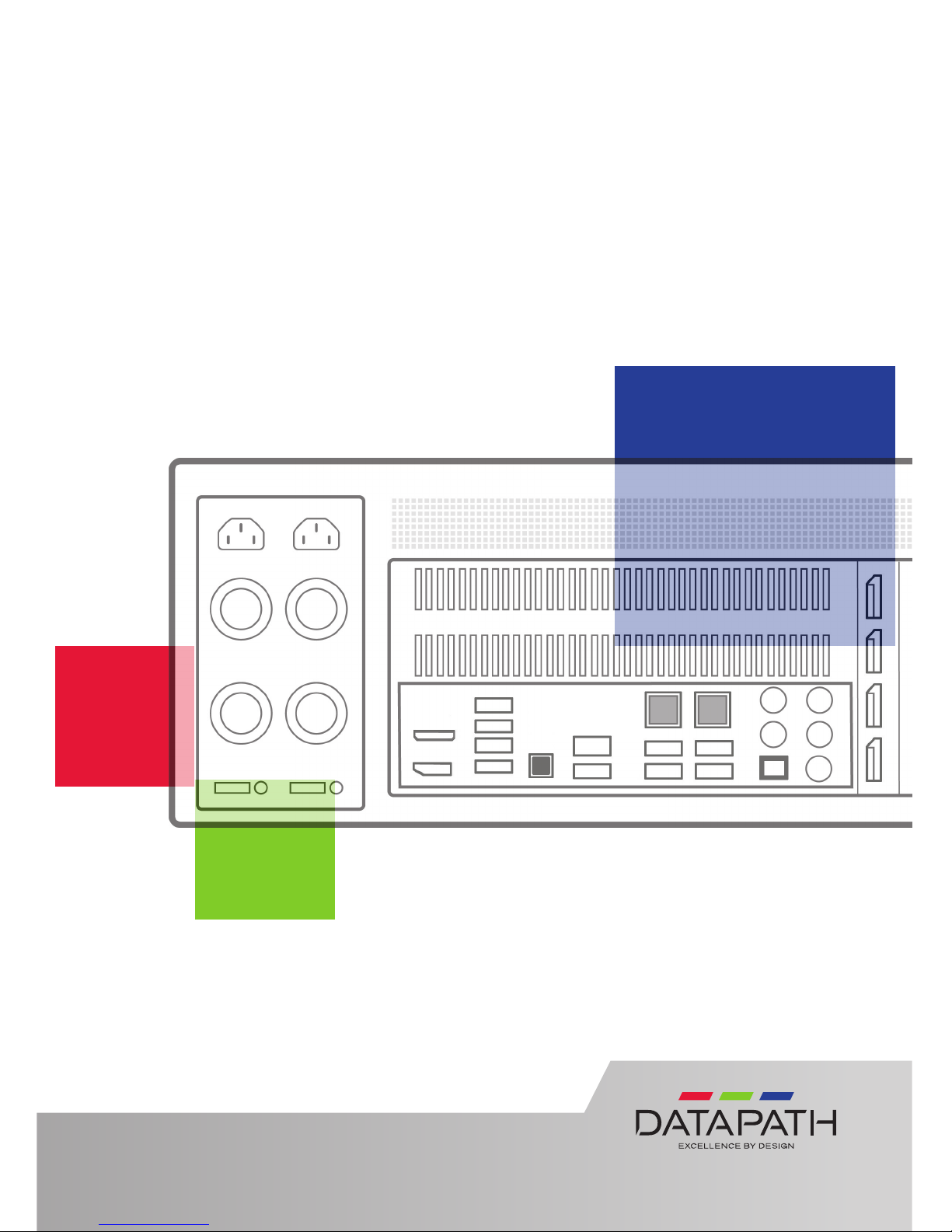
Wall Controller
Quick Start Guide
VSN400 Series of Wall Controllers

STEP 1 CONTENTS
QUICK START GUIDE
Page 2
STEP 2 KEYBOARD AND MOUSE
Connect Keyboard and Mouse to USB Ports. USB ports can be
found on the front and rear of the chassis.
Main System
VSN400 Main chassis
Mouse/Keyboard
Recovery Media
Accessories Pack
Mains Cable
Build Log
In addition, if any optional cards are installed:
PCIe card product leaets
Cables/Adapters as specied in the product leaets
Each Datapath system is custom built therefore the number and type of input and
output cards will dier from system to system.
Accompanying this Quick Start Guide are PCIe card product leaets which give
details on how the cards are installed and any accessories supplied with them.
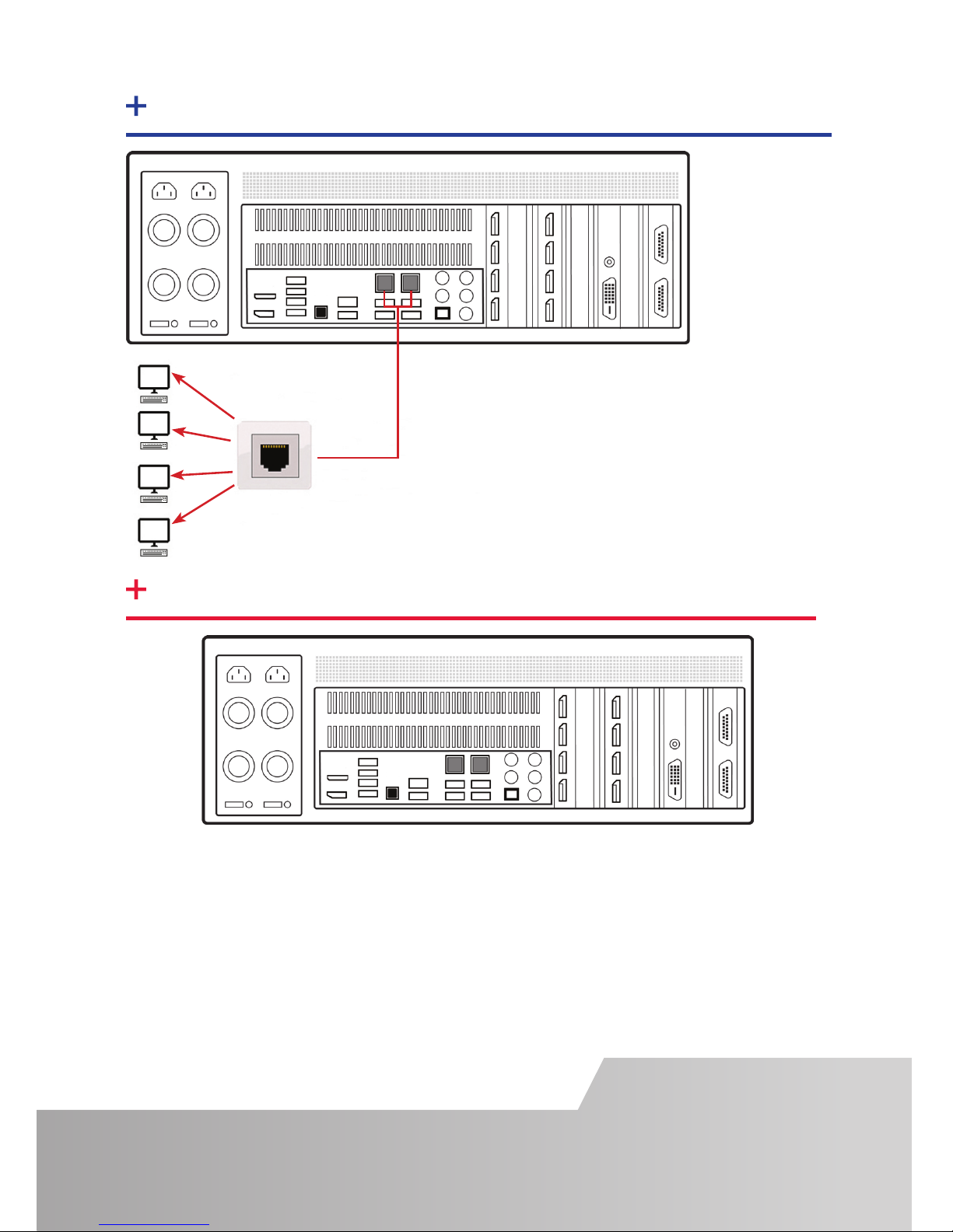
STEP 3 CONNECT TO A NETWORK (OPTIONAL)
Page 3
STEP 4 CONNECT INPUT SOURCE
Each Datapath system is custom built. The number and type of inputs will dier
from system to system.
Contained within the documentation pack are PCIe card product leaets which give
details on how the cards are connected.
The I/O panel on your system may dier from the above illustration depending on
which motherboard option you have purchased. Refer to the motherboard
documentation for more details.
Network Cable not supplied.
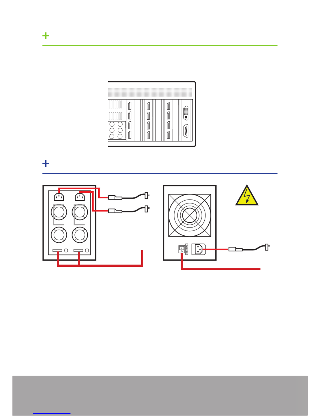
Connect power cables then plug into a
mains supply.
Switch on the power supply units.
2
1
RPSU System
ATX System
1
2
2
1
STEP 5 CONNECT AN INPUT SOURCE
To enable you to complete the initial setup of the system, displays must be connect-
ed to the rst and second output as shown below.
1
2
STEP 6 POWERING UP THE SYSTEM
Page 4
 Loading...