

Page 1
Thank you for purchasing the Datapath iolite 12i wall controller. The
aim of this document is to quickly guide you through the process of
initial setup. For detailed instructions consult the system User Guide
which can be found on the Documentation Media.
Quick Start Guide
www.datapath.co.uk | sales@datapath.co.uk | +44 (0) 1332 294441
iolite 12i
Page 2
IOLITE 12I QUICK START GUIDE
Page 2
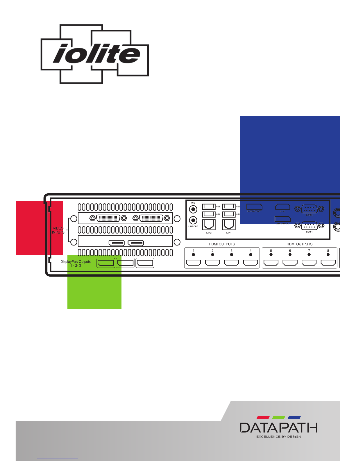
Each Datapath iolite 12i is custom built to order therefore the components, number
and type of inputs will dier from system to system.
Each iolite 12i is shipped with a printed diagram outlining the specic types of
input(s) and where they are located on the rear panel of the system.
Any input cables supplied are clearly labeled and will indicate which of the video
input connectors they relate to.
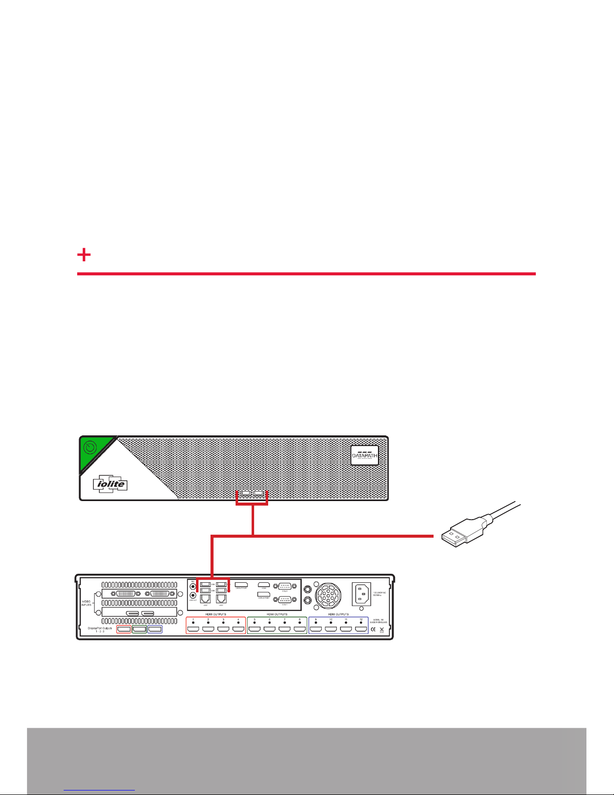
Connect Keyboard and Mouse to convenient USB Ports.
USB Ports are located on both the front and rear panels of the system. If the
intention is to mount the iolite12i in a rack, it may be more convenient to use the
USB ports on the front for easy access.
• 4 x USB 3.0 ports on the rear panel
• 2 x USB 2.0 ports on the front panel
STEP 1 KEYBOARD AND MOUSE
Front Panel
Rear Panel
Page 3

STEP 3 CONNECT VIDEO INPUT SOURCES
Page 3
Input Connectors
As each iolite 12i is custom built, the number and type of video inputs will dier
from system to system. If you have purchased an iolite 12i with video inputs, the
input connectors are located on the rear panel as shown below.
The printed diagram shipped with the iolite 12i shows the types of input and
connectors built into your specic system.
Connect the input sources to the relevant input connectors, cables may be supplied
for some inputs. See content list for details.
If the iolite 12i is to be used over a network, connect the iolite 12i to a network
point (cables not supplied) using one of the LAN connectors on the rear panel.
STEP 2 CONNECT TO A NETWORK (OPTIONAL)
Page 4
Page 4
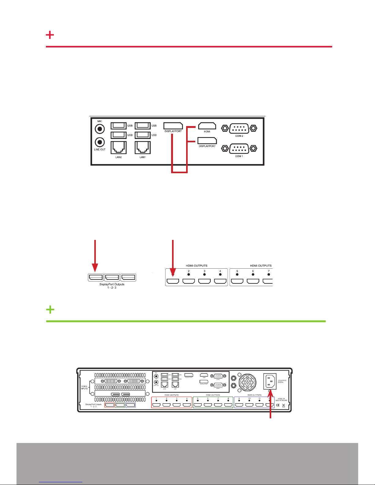
Your iolite 12i is factory congured to use a control screen connected to the system
internal graphics device. Connect the control screen to one of the two DisplayPorts
or the single HDMI connector on the motherboard panel on the rear of the iolite
12i. A control screen is initially required to set up the system including the operating
system (Windows 10).
If a control screen is unavailable, connect a single video wall display into either the
DisplayPort 1 or HDMI 1 output connector on the rear of the iolite 12i.
Connect the power cable into the rear of the iolite 12i (1) then plug into a mains
supply.
1
DisplayPort 1 HDMI 1
Control Screen connections
STEP 4 CONNECTING A CONTROL SCREEN
STEP 5 POWER UP THE SYSTEM
Page 5

Page 5
STEP 7 DISPLAY WALL CONFIGURATION
Press the on/o button (2) to power up the iolite 12i. There will be a short delay
followed by the sound of the internal fan. The fan noise will subside when the
system has fully booted.
2
Once the system has been built and congured in our factory the operating system is
resealed, therefore when switching the system on for the rst time, the operating
system setup commences. You will be prompted to enter information to set up the
Windows 10 operating system.
There is no requirement for users to activate Windows 10, activation is done
automatically. An internet connection is required to complete the automatic
activation.
STEP 6 WINDOWS 10 SETUP
Once the Windows 10 setup is complete, the system will reboot and the control
screen will show a Windows desktop displaying the Display Driver Conguration Tool
(DDCT). The DDCT will guide you, step by step, through the conguration of the
graphics outputs, enabling you to quickly create one or more video walls.
On the nal stage of the conguration, the DDCT will recommend the optimum way
to connect your iolite 12i to your video wall displays.
A full description of the DDCT can be found in the User Guide located on the
Documentation Media.
Page 6

Page 6
Select the type of displays being used on your wall:
• Displays With Bezels – Monitors, TVs and DLP Cubes.
• Overlapable Displays – Projectors.
• LED Displays.
Click on “Continue”.
The tool will then display a conguration page for the type of display you selected.
It is recommended that you carefully read the instructions on each page of the
wizard. To commence your wall conguration, click on “Start Wizard” .
Page 7

Page 7
Add Displays
Add Displays is available for displays with bezels or overlapable displays. Use the
“Displays Across” and the “Displays Up” to create your Display Group. Once
created, congure the displays using “What Type of Displays Do You Have?” When
using overlapable displays “Display Overlap” becomes available, enabling you to
select a percentage of overlap between displays.
What Type of Displays do you Have?
Use the “Manufacturer” and “Model” dropdown lists to select the displays you are
using for your wall. If the wall consists of dierent displays, select each one in turn
to congure the type of display. The DDCT has an extensive database of displays,
however if your display is not contained in the list, you can input the details manually
by selecting “Create Custom Display”.
It is strongly recommended that measurements are taken from the display
manufacturer’s specications if available.
Once the layout has been created and the type(s) of displays congured click on
“Add Displays & Continue” and the following dialogue is displayed:
Page 8

Page 8
At this stage of the set up you can choose to create another independent display
group from the same system, this would be considered if one machine will be used
to drive a number of separate video walls. See User Guide for more details.
If another display group is not required, click on “Finish” and the following page is
displayed:
The DDCT can recommend the best wiring conguration for your system, ensuring
the load is balanced between the graphics hardware. Click on “Recommended” for
the optimal conguration for your system.
Should you wish to manually wire your system and decide for yourself which output
is connected to which display, click on “Custom”. Use the conguration matrix in
Chapter 5 of the User Guide to determine the connection combinations available.
You will be next be presented with the Summary page:
Page 9

Page 9
If you chose to have the DDCT congure your wiring this page will display the
recommended connections, as shown above. Connect each display to the
corresponding output connector on the rear of the iolite 12i. If your iolite 12i is
connected to a printer, you can print a copy of the wiring diagram using “Print a
Wiring Diagram”.
Note: The Datapath Diagnostic Suite must be installed to print a wiring
diagram. The suite can be downloaded from the Datapath website downloads page.
To manually select the outputs right click on the display group and select “Edit”, you
can then select each individual display and allocate your preferred output . Right
click on a selected display to reveal the list of outputs available:
When all outputs have been allocated by either “Recommended” or “Custom” click
on “Finish”. You will then be prompted to save the changes to your video wall and
restart your system. When restarted, the Windows Desktop will be displayed across
the wall.
You can access the conguration tool at anytime should you wish to make changes.
Right click on the desktop and select Display Driver Conguration Tool from the
menu.
Page 10

Start | All Programs | WallControl 10 - Client
1
2
3 4
5
1 Indicates the server you are connected to.
2 A representation of the display wall associated with the server.
3 Sources Tab - Displaying all the sources connected to the server for use on
your display wall.
4 Layouts Tab - Use to save, recall and share display wall layout congurations.
5 Templates Tab - Use templates to assist in the design of specic display wall
layouts.
Open the WallControl 10 Client
STEP 8 WALLCONTROL 10
Start | All Programs | WallControl 10 - Server
Before opening the WallControl 10 Client interface you may need to start the
WallControl 10 Server should it not start automatically. The Server icon is displayed
in the System Tray.
Page 10
If the Server fails to start automatically, start the Server by clicking on it in the
“All Programs” menu. The WallControl 10 Client will only detect servers that are
running.
Server icon
Page 11

Click on the display wall representation to open the display wall tab (2).
When opened, the display wall tab shows a live representation of the physical wall
and the sources available to display on it. To place a source on the video wall, simply
click on the required source in the Sources Tab and drag it onto a preferred position
on the display wall representation.
The application help le is accessed using the question mark icon (?) located on the
top right of the WallControl 10 Client. The help le contains information explaining
how multiple sources can be selected, how to use and create templates, how to
save, recall and share layout les and manage walls.
Sources
Display Wall
Tab
Display Wall
Representation
The WallControl 10 - Security Administration Client (Only Available with
WallControl 10 Pro)
Start | All Programs | WallControl 10 - Security Administration Client
Page 11
A WallControl 10-Pro serial dongle must be inserted into a vacant USB port. If the
dongle is removed or swapped, the Security Client will not open and an error
message is displayed, therefore it is important the dongle is not removed.
If you have purchased WallControl 10 Pro, the licence dongle can be located in the
accessories box.
Page 12

The WallControl 10 - Security Administration Client allows Administrators to assign
specic users to roles on a wall by wall basis. For example, a user can be assigned
a role allowing unrestricted access on one wall but assigned a role on another wall
which only allows the opening of pre-determined layouts.
Prior to the Security Client being used for the rst time, the SecurityOnO.exe
program must be running to enable security protection for the application. To
manually run the SecurityOnO.exe, ensure you are logged into Windows® with
Administrator Rights.
Locate and double click on the SecurityOnO.exe le:
Program Files|WallControl 10| Security Server|SecurityOnO
The WallControl 10 Security Application help le contains information on how to:
• Import users from the Windows Active Directory into the database.
• Create and edit roles.
• Assign permissions to providers, layouts and sources giving specic roles
access to them.
• Assign roles to walls.
Page 12
Page 13

© Datapath Ltd., England, 2018
Datapath Limited claims copyright on this documentation. No part of this
documentation may be reproduced, released, disclosed, stored in any electronic
format, or used in whole or in part for any purpose other than stated herein without
the express permission of Datapath Limited.
Whilst every eort is made to ensure that the information contained in this Quick
Start Guide is correct, Datapath Limited make no representations or warranties with
respect to the contents thereof, and do not accept liability for any errors or omis-
sions. Datapath reserves the right to change specication without prior notice and
cannot assume responsibility for the use made of the information supplied. All
registered trademarks used within this documentation are acknowledged by
Datapath Limited.
EU – Class A Declaration of Conformity
Datapath Ltd declares that this product complies with the essential requirements
and other relevant provisions of Directives 2014/30/EU, 2014/35/EU and 2011/65/EU.
A copy of our Declaration of Conformity is available on request.
Datapath Limited
Bemrose House
Bemrose Park
Wayzgoose Drive
Derby, DE21 6XQ
UK
A full list of product compliance certications can be found in the system User Guide
on the Recovery Media supplied with the system.
Page 13
Page 14

NOTES:
Page 14
Page 15

Page 14
Page 16

Product iolite 12i Quick Start Guide
Classication Released
Version Number 2.0.0
Datapath UK and Corporate Headquarters
Bemrose House, Bemrose Park
Wayzgoose Drive
Derby, DE21 6XQ
England
+44 (0) 1332 294441
sales@datapath.co.uk
Datapath North America
2550 Blvd of the Generals
Suite 320
Norristown, PA 19403
USA
+1 484 679 1553
sales@datapath.co.uk
Datapath France
+33 (1)3013 8934
sales-fr@datapath.co.uk
Datapath Germany
+49 1529 009 0026
sales-de@datapath.co.uk
Datapath China
+86 187 2111 9063
sales-cn@datapath.co.uk
Datapath Japan
+81 (0)80 3475 7420
sales-jp@datapath.co.uk
Page 15
 Loading...