

Page 1

Multi Display Controller
USER GUIDE
Version 1.0.0
Page 2

Contents
2
Table of Contents
Chapter 1 - Introduction..............................................................................................................4
1.1 Introduction.............................................................................................................................................................4
1.2 How the User Guide is Organised .............................................................................................................................4
1.3 Fonts and Symbols...................................................................................................................................................4
Chapter 2 - Safety.......................................................................................................................5
2.2 Unpacking and Initial Inspection...............................................................................................................................5
Chapter 3 - General.....................................................................................................................7
3.1 Overview...................................................................................................................................................................7
3.2 Features....................................................................................................................................................................7
Chapter 4 - Hardware..................................................................................................................8
4.1 Front Panel...............................................................................................................................................................8
4.2 Rear Panel................................................................................................................................................................8
4.3 Rack Mounting the Fx4.............................................................................................................................................9
Chapter 5 - Software..................................................................................................................10
5.1 Wall Designer..........................................................................................................................................................10
5.2 Wall Designer Features...........................................................................................................................................10
5.4 Running the Wall Designer Application....................................................................................................................11
Chapter 6 - Cabling....................................................................................................................13
6.1 Connecting a Sync Cable..........................................................................................................................................13
6.2 Attaching an HDMI Cable Lock.................................................................................................................................13
6.3 Connecting Input Sources........................................................................................................................................13
6.4 Connecting the Out Loop........................................................................................................................................14
Chapter 7 - Operation.................................................................................................................15
7.1 Setting up the Fx4...................................................................................................................................................15
7.2 Switching On the Fx4..............................................................................................................................................15
7.3 Conguring the Fx4 via USB....................................................................................................................................16
7.4 Conguring the Fx4 via a Network...........................................................................................................................18
Page 3

Table of Content
Contents
3
Chapter 8 - Troubleshooting .......................................................................................................19
8.1 Troubleshooting.......................................................................................................................................................19
8.2 Technical Support ...................................................................................................................................................19
Chapter 9 - Maintenance............................................................................................................20
9.1 Maintenance of the Fx4 ..........................................................................................................................................20
Chapter 10 - Environmental ........................................................................................................21
10.1 Certication and Compliances................................................................................................................................21
Chapter 11 - Specications..........................................................................................................22
Chapter 12 - Warranty/RMA ........................................................................................................23
12.1 Warranty Statement..............................................................................................................................................23
12.2 RMA Returns Policy................................................................................................................................................23
Chapter 13 - Index......................................................................................................................25
Page 4
Introduction
4
Chapter 1 - Introduction
1.1 Introduction
Congratulations on your purchase of the Datapath Fx4 Multi Display Controller. The Fx4 has been manufactured and tested to
the highest standards oering unparalleled quality and reliability. The aim of this user guide is to assist you through the
installation of the Fx4 safely and eectively and act as a reference guide for future use. Do not switch the controller on until all
the relevant cables have been connected.
1.2 How the User Guide is Organised
The user guide is broken down into chapters and each chapter into sections. Chapters, sections and pages are numbered
individually. Pages are numbered in Arabic numerals with the exception of the cover page (no numbering).
1.3 Fonts and Symbols
1.3.1 Fonts
The font used throughout the user guide is Corbel however the following font styles mean:
Bold = Used to describe menu titles, buttons in software or elements that you must type.
Blue Underlined = Indicates a hyper-link. Some hyper-links may be linked to live websites.
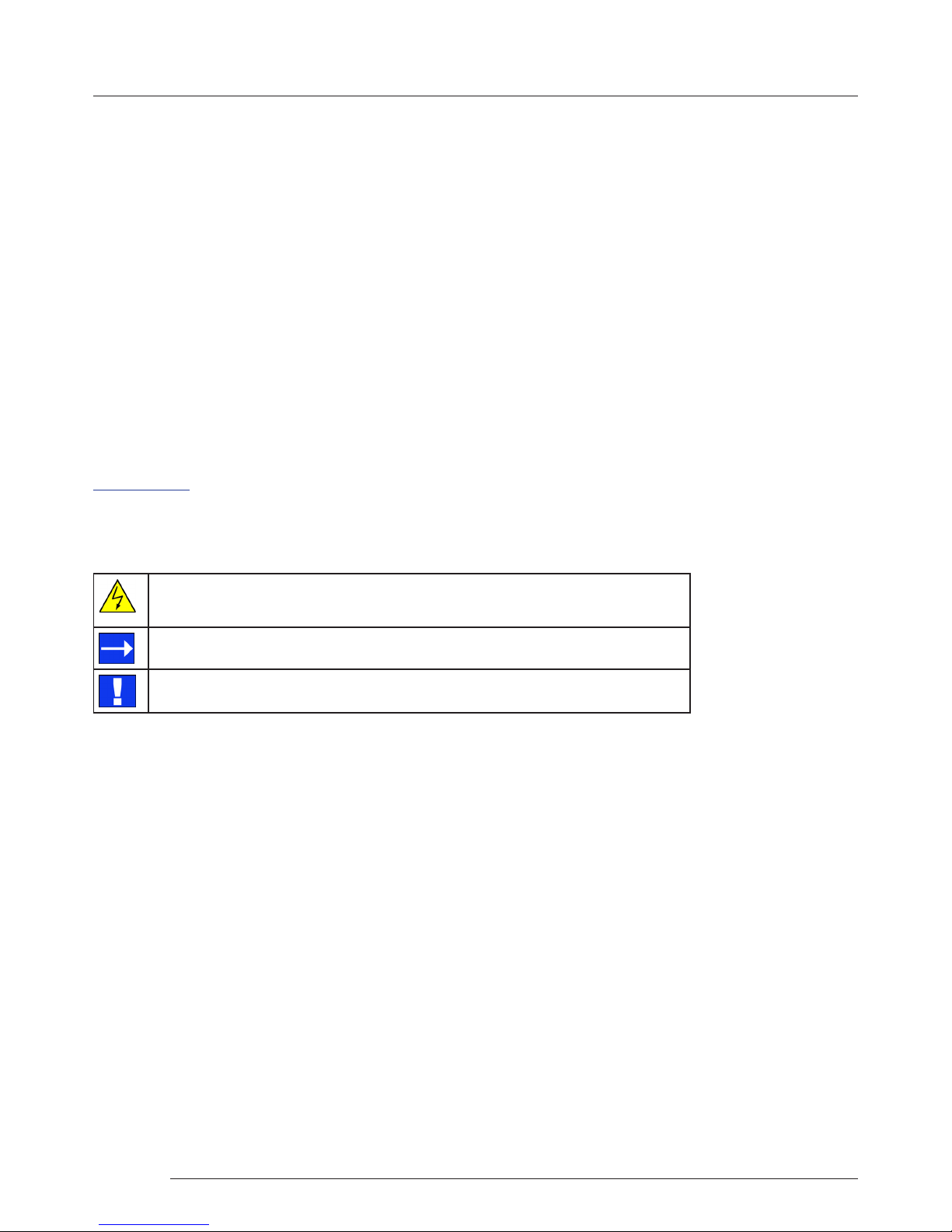
1.3.2 Symbols
Symbols are used throughout this user guide to assist the user in quickly identifying important safety information and notes.
Yellow triangle indicates that failure to observe the instructions could result in injury
and/or damage to the system.
White arrow in a blue box indicates a useful tip.
White exclamation mark in a blue box indicates important information.
Page 5

Safety
5
Chapter 2 - Safety
2.1 Safety Precautions
To prevent damage to your Datapath product or injury to personnel operating the equipment, please read the following safety
precautions prior to operation. These instructions should be made available to all those who will use and operate Datapath
products.
2.1.1 Power Supply
All Datapath products require a mains power supply. This power supply must be disconnected when equipment is being
relocated.
2.1.2 Cables
Do not expose cables to any liquids; doing so may cause a short circuit which could damage the equipment. Do not place heavy
objects on top of any cables as this can cause damage and possibly lead to exposed live wires.
2.1.3 Ventilation
The Fx4 should be located in a well ventilated area. All ventilation holes on the casing must be kept clear of any obstruction at
all times. Failure to do so will result in the system over heating and damaging your equipment.
2.1.4 Working Environment
The equipment should be located in an environment free from dust, moisture and extreme changes in temperature and should
be placed on a stable and solid work surface. Liquids (hot/cold drinks etc) should not be placed near the equipment as spillage
could cause serious damage.
2.1.5 Gas/Flammable Liquids
Electronic equipment should never be used in the presence of gas or any ammable liquid, doing so could result in an explosion
or serious re.
2.1.6 Smoke/Unusual Smells
Should you notice smoke or unusual smells being emitted from your system, turn o and unplug the system from the mains
supply. The system should then be passed to a qualied technician for inspection. Continued operation could result in personal
injury and damage to property.
2.1.7 Maintenance
Apart from what is detailed in this user guide, maintenance should only be carried out by competent technicians, Fx4’s that are
physically damaged should be returned to Datapath for repair using Datapath RMA procedures.
2.2 Unpacking and Initial Inspection
2.2.1 Unpacking
All packaging materials should be retained for future transit.
Page 6

Safety
6
2.2.2 Initial Inspection
All Datapath products are carefully prepared for shipment and every eort is made to ensure you receive the product in pristine
condition. On receipt, you should carefully inspect the outer packaging for any transit damage i.e. any signs that the item may
have been dropped etc.
Use the product leaet enclosed to establish that all the items are present. Should any items be missing, contact Datapath for
further instructions.
Check the Fx4 for damage that could have an adverse aect on the operation of the system or could cause injury to the
operator. Should there be any physical damage to the power sockets or exposed wiring do not connect to a power source, contact Datapath for further instructions.
2.3 Unpacking
Your packing box should contain the following items:
• The Fx4 Multi Display Controller
• 1 x Mains power cable
• USB 2.0 cable Type A to Type B
• Quick Start Guide
• HDMI Locks: x 2 with the DisplayPort model
x 6 with the HDMI model
• 2 x Rack mount attachments
• 6 x Rack mount screws
• Datapath CD containing Wall Designer Software Application and the Fx4 User Guide.
If any of the items are missing, please contact Datapath for further instructions.
Safety
Page 7

General
7
Chapter 3 - General
3.1 Overview
Advancements in digital signage requirements mean that customers demand greater freedom in creating and deploying small,
medium and large scale signage projects. The Datapath Fx4 is a multi-faceted stand alone display controller that supports a
choice of inputs, high bandwidth loop-through as well as four gen-locked outputs in either DisplayPort or HDMI.
The Fx4 features a DisplayPort 1.2 alongside two HDMI 1.4 inputs oering up to 4k (4096x2160p) at 60fps or UHD (2160p) at
30fps respectively. The intuitive user interface, Wall Designer (See Chapter 5) allows users to determine which input is used.
The Datapath Fx4 has dual Ethernet ports to allow users to add the device to their networks. Only one Datapath Fx4 in the
chain requires connection to the physical LAN as Ethernet loop through is supported on the second port, meaning multiple
devices can be connected.
3.2 Features
Each output monitor can take its input from any region of the input image as all of the required cropping, scaling, rotation and
frame-rate conversion is handled by the Datapath Fx4 hardware. These regions can overlap to allow any output to replicate
another or can be congured to support any creative splice of the source material. This allows the support of many
non-rectangular screen arrangements with uneven gaps, and any mix of monitor orientations.
• Innite creative congurations
• Up to Ultra HD input, four HD 1080p outputs
• Rotates, crops, scales, mirrors and bezel corrects
• Dual HDMI 1.4 and single DisplayPort 1.2 inputs for 4k 60 fps source capture
• HDCP support on all inputs and outputs
• Stand alone operation: Non-volatile conguration can adapt to changes in inputs by automatically adjusting all scale
factors
• Power down conguration save facility, power up instantly with no re-setup required
Page 8
Hardware
8
Chapter 4 - Hardware
4.1 Front Panel
POWER
INPUT
STATUS
4.1.1 Operation Indicators
The front panel has three LEDs to indicate the operational status of the Fx4:
• Power
• Input
• Status
Power
When illuminated, the Power LED indicates the Fx4 is connected to a mains supply.
Sync
The Sync accepts Tri-level or Black burst syncs for genlocking the Fx4 to external devices.
Inputs
The Fx4 has 3 input connectors, 1 x DisplayPort and 2 x HDMI . All 3 inputs can be connected to sources playing concurrently,
however only 1 of the inputs can be displayed at any one time. Switching between inputs is achieved using the Wall Designer
software application.
Input
When illuminated, the Input LED indicates a valid source is connected.
Status
Continuous illumination – Indicates the Fx4 is operating normally.
Flashing – Unit is operating over the normal operating temperature. Ensure the input fan vent is not blocked.
If the Status LED goes o and remains o this indicates that the settings congured in Wall Designer no longer match the input,
this is normally the result of a change of input. The Fx4 will compensate for the settings and recongure itself to display as near
to the settings as possible. The output will still be displayed but not necessarily as expected.
When the Fx4 device is connected to a PC by a USB cable and Wall Designer application is active, then all three lights ash in
turn to help to identify which unit is being controlled.
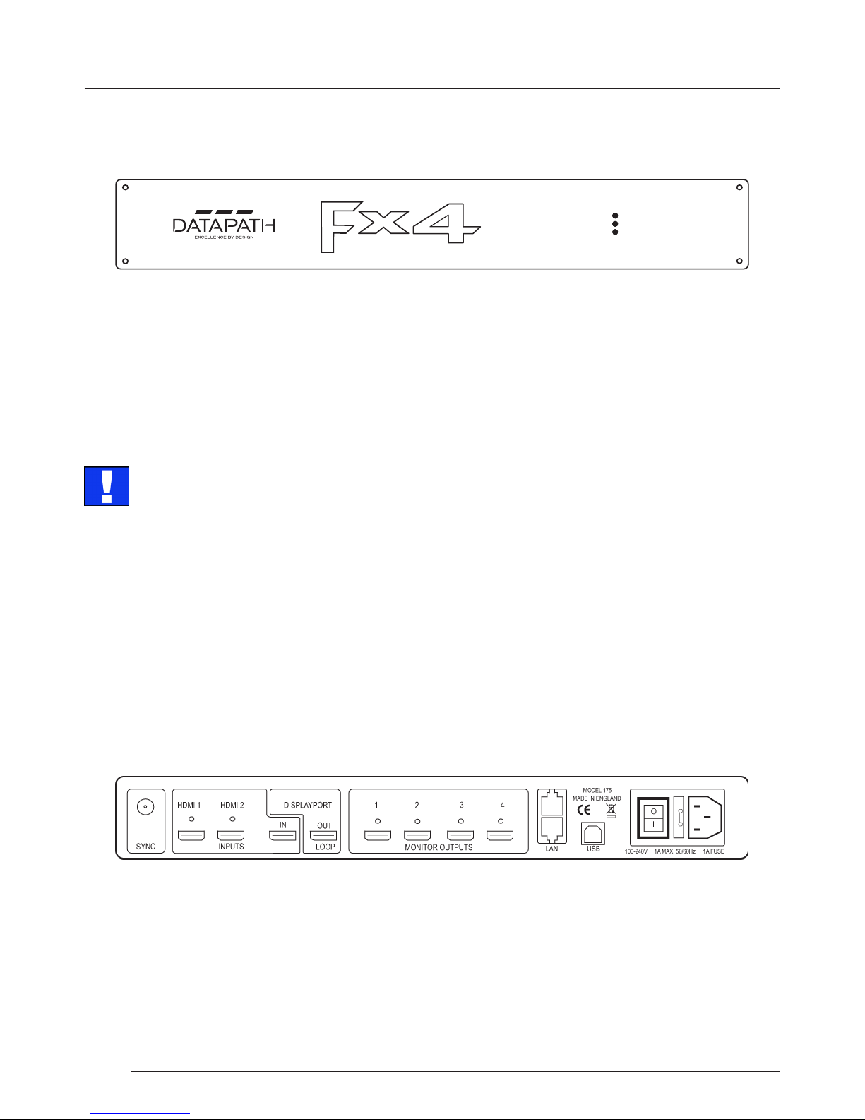
4.2 Rear Panel
The LED’s can ash for up to 15 seconds when the Fx4 is switched on.
Page 9

General
9
Hardware
DisplayPort Out Loop
Used to connect multiple Fx4 systems enabling larger display walls.
Monitor Outputs
Either HDMI or DisplayPort (DP 1.1) output connectors (depending on model ordered). The Monitor Output connectors are
used to connect the Fx4 to the display monitors.
LAN
The LAN connector is used to connect the Fx4 to a network for conguration and control, it can also be used to connect
multiple Fx4 in a daisy chain architecture using Ethernet cables. Ethernet loop through is supported. The LAN connector can
also be used to connect the Fx4 to a PC for conguration.
USB
The USB socket is used to connect the Fx4 to a PC via a USB connection using the supplied USB Type A to Type B cable.
4.3 Rack Mounting the Fx4
The Fx4 is supplied with attachments to enable you to mount the Fx4 in a rack. Remove the 3 mounting screws on each side of
the Fx4 using a cross head screwdriver and attach the rack mounts as shown in the illustration below.
Remove the stud
screws and secure
rack mounts
using the screws
provided
Page 10

Software
10
Chapter 5 - Software
This chapter will cover:
Introduction to Wall Designer
Installing the Wall Designer application
Running the Wall Designer application
A summary of Wall Designer features
5.1 Wall Designer
Multi-Monitor Display Wall installations can be challenging to design, build, congure and implement. Highly creative display
projects often require multiple monitors arranged in unconventional formations with a myriad of bezel sizes, gaps and monitor
positions. Project designers, installers and integrators require simple yet eect Video Wall creation tools in order to manage the
project from start to nish.
The software includes a community driven database of monitors from popular manufacturers which continues to grow as users
add their own monitor specications and submit them back to Datapath for inclusion in the next database update.
5.3.1 Software CD
The Datapath Software CD supplied with your Fx4 display controller contains the Wall Designer application. It is recommended
that users regularly visit the Datapath website for information on new software releases.
Insert the software CD into a CD/DVD drive and the installation wizard should begin automatically. Should the installation
wizard not start, browse the CD, locate and double click SetUp.exe and the following dialogue is displayed.
5.2 Wall Designer Features
Wall Designer is the perfect solution to creating and managing your display wall project from start to nish, giving you total
creative control reliably and eciently.
• Datapath’s monitor database is regularly updated with new manufacturers and models. Users can add and submit their
own monitor information and once validated, will be added to the master database.
• Monitors can be arranged landscape and portrait with gaps.
• Add content into your project and place it across the virtual canvas lling the monitors with content.
• Automatically congure the Fx4 assigning each output to a monitor.
• Print out design schematics to aid physical monitor installation.
• Language support for German. Spanish, French, Japanese, Polish, Portuguese, Russian and Simplied Chinese.
• Comprehensive help les to guide you through the application.
5.3 Installing the Wall Designer
Page 11

Software
11
Start | All Programs | Wall Designer
5.4.1 Wall Designer Interface
When Wall Designer is opened, the following dialogue is displayed:
1
2
3 4
5.3.2 Install the Wall Designer Software
Click on Install Wall Designer to initiate the installation wizard. Wall Designer is a multi-lingual application and you are oered
a selection of languages when the install process begins. Select the required language and the install wizard will continue
installing the software.
5.3.3 View Readme
Click on View Readme to open an HTML document containing the latest information and bug xes for the application. The Wall
Designer application can be installed from the Readme.
5.3.4 View User Guide
Click to open the user guide in PDF format.
5.3.5 Install Acrobat
Install Acrobat is provided to enable you to read the PDF User Guide.
5.4 Running the Wall Designer Application
Once the software has been installed you can open the application:
Software
1 Operation Modes: Select monitors, inputs and congure devices
2 Quick Tour Dialogue
3 Virtual Canvas
4 Toolbar
Page 12

Software
12
Software
5.4.2 Operation Modes
The application has 3 separate operation modes: Monitor, Inputs and Devices:
Monitors
Wall Designer includes a database containing a selection of the more commonly used monitor manufacturers and model. Use
the manufacturer and models dropdown list to select a specic monitor. When selected the monitor properties are
automatically populated with the specication of the monitor.
To add monitors simply click or click and drag the cells inside the 8x8 grid. Once the monitors have been arranged on the virtual
canvas and you are happy with the wall design, click on Add Monitors to Wall.
Add a background image to enhance the Virtual Canvas.
Inputs
The inputs section of the application toolbar enables you to select a given input and allocate regions of the input to each
monitor on the display wall.
A collection of sample sources are available via a dropdown menu, this contains a list of images and videos contained within the
application’s and user’s media folder.
Devices
The devices section of the application toolbar brings together the input, hardware devices and the monitors thereby
completing the design of your display wall. This is done by allocating the input to available devices and the outputs from the
devices to specic monitors on the display wall.
For ease of use Wall Designer has an automatic conguration feature (Auto-cong) which when clicked, automatically adds the
required number of devices and congures all the links from the input to the monitors via your Fx4’s in the most logical
conguration.
The virtual device can be associated with an actual device by right clicking on it and selecting Associate Device. Click in the
device to display the device properties, these properties can be changed if required, for example the Friendly Name
(recommended).
5.4.3 Quick Tour
When opening the application for the rst time a quick tour dialogue is presented. It is highly recommended that you take a
few minutes to complete the tour. The quick tour dialogue can be turned o so it will not be displayed in the future.
5.4.4 Virtual Canvas
The Virtual Canvas displays a representation of the monitors selected and their orientation, thereby oering a view of the
completed wall design. In Device mode, the Virtual Canvas illustrates how the input source, Fx4(s) and monitors are congured.
5.4.5 Toolbar
The toolbar oers a group of tools which assist in creating, opening and saving layouts, you can also display actual video wall
measurements in metric or imperial.
5.4.6 Help Files
The Wall Designer application has a an inbuilt help le system which can be accessed by clicking on the ? at the top of the
toolbar.
Page 13

Cabling
13
Chapter 6 - Cabling
This chapter will cover:
Connecting a House Sync cable.
Attaching HDMI Cable Lock.
Connecting input sources.
Connecting a loop-through output cable.
Connecting the outputs to monitors
Cable lengths
6.1 Connecting a Sync Cable
The Sync BNC connector supports tri-level and black burst video signals which is used to genlock the 4 monitors. For multiple
Fx4’s, a distribution unit is required (not supplied).
6.2 Attaching an HDMI Cable Lock
The Fx4 is supplied with HDMI cable locks which should be used on non lockable HDMI cables to ensure they remain rmly
attached to the Fx4.
Connecting HDMI Input Cable
6.3 Connecting Input Sources
The Datapath Fx4 has three dedicated input connectors 2 x HDMI and 1 x DisplayPort. It is strongly recommended that locking
cables are used to prevent the input source cables from becoming detached from the Fx4. HDMI Cable Locks are provided and
should be attached to your cables as shown above:
Thread the cable tie through the
holes in the side of the cable lock.
Sit the cable lock on the top of the
HDMI cable connector ensuring the
cable lock is ush with the front of
the shroud on the HDMI connector.
Pull the cable tie tightly and ensure
it ts rmly on the HDMI connector
shroud.
Page 14

Cabling
14
Cabling
6.5 Connecting Outputs to Monitors
Each Fx4 display controller can support up to 4 monitors on a display wall, the output connectors will be HDMI or DisplayPort
depending on the model ordered. Once again it is highly recommended that locking cables are used.
Each output can display any region of the input image, all the required cropping, scaling and rotations is calculated within the
Fx4 hardware.
Cable Type Bit Rate Maximum Length (m)
HDMI (output) N/A 10
DisplayPort (output) Reduced Bit Rate (RBR) 20
DisplayPort (output) High Bit Rate (HBR) 10
DisplayPort (Loop through) Reduced Bit Rate (RBR) 20
DisplayPort (Loop through) High Bit Rate (HBR) 10
DisplayPort (Loop through) High Bit Rate 2 (HBR2) 2
Ethernet Cable (Network/Setup) N/A 100
USB (Setup) N/A 3
6.4 Connecting the Out Loop
The Out Loop connector is used to connect two or more Fx4’s when the requirement is to create large video display walls with
more than 4 monitors.
Using a DisplayPort cable (not supplied) connect the Out Loop from the rst Fx4 to the DisplayPort Input on the second Fx4
and so on until all the required units are connected. The input signal will be gen-locked through all the connected Fx4’s in the
chain.
6.5.1 Cable Lengths
Workable cable lengths depend on the quality of the cables used to set up your Fx4, Datapath recommends using certied
cables when installing your Fx4.
Connecting HDMI Output Cable
The Wall Designer software has a Maximum Link Rate selector which enables you to manually select the link rate of the
DisplayPort input to suit your own requirements. The default rate of HBR2 allows operation up to the full 4k/60 capability of the
DisplayPort input, but if the actual input signal is only HD then the maximum link rate can be changed to HBR or RBR to enable
the use of longer cables.
Page 15

Operation
15
Chapter 7 - Operation
This chapter will cover:
Setting up
Switching on the Fx4
Conguring the Fx4 using a USB connection
Conguring the Fx4 over a Network
7.1 Setting up the Fx4
7.1.1 Connecting an Input
Firstly, ensure you have all the relevant input and output cables you need for your project:
• Begin by connecting your input source to one of the 3 input connectors on the rear of the Fx4. You can connect up to 3
input sources, 2 x HDMI and 1 x DisplayPort. If using more than one Fx4, the DisplayPort Input connector will act as the
loop through input on the additional devices. Ensure the input cables are inserted correctly, it is recommended that locking
cable connectors are used.
HDMI DisplayPort
7.1.2 Connecting Outputs
Depending on the Fx4 model ordered, either HDMI or DisplayPort cables are required (not supplied). The Fx4 has 5 output
connectors, 4 x monitor outputs and 1 x DisplayPort loop through.
• Connect the monitor cables to the monitor output connectors on the rear of the Fx4, you can connect up to 4 monitors to a
single Fx4 unit. Ensure the cables are inserted correctly, it is recommended that locking connectors are used.
• The DisplayPort Out Loop is used to when connecting multiple Fx4 units. See Chapter 6 for cabling requirements.
HDMI or DisplayPort
Output Connectors
DisplayPort
Out Loop
7.2 Switching On the Fx4
The Fx4 has a built in power unit which is controlled using the power switch on the rear panel. Connect in the power cable
supplied with your Fx4 and plug in to a mains supply. Switch on the power on the rear of the Fx4 as shown in the following
illustration:
Page 16

Operation
16
Operation
Power Switch
When the power is switched on the Fx4 will boot and the LEDs on the front panel will ash as described in Chapter 4.
Please note, it could take up to 15 seconds for the Fx4 to fully boot.
7.3 Conguring the Fx4 via USB
When the Fx4 has booted, connect it to the computer which has the Wall Designer application installed using the USB cable
provided.
USB Port
Open the Wall Designer application and begin to design your video wall layout using the Monitors tab as described in Chapter 5.
With the monitors selected and the layout completed select the Input tab. Allocate the input to the Fx4 by clicking on Create
then selecting the required input from the drop down menu.
Once the input has been selected, navigate to the Devices tab, this is where the Fx4 is congured.
The Devices window is where the input, devices and monitors are linked to complete the design of the video wall; this is done
by allocating inputs to devices and the outputs from the devices to specic monitors on the video wall.
For ease of use the Auto-cong Fx4 function will, when clicked, automatically add devices and congure all the links from the
inputs to the monitors via the Fx4 in the most logical conguration.
Click on the Auto-cong Fx4 button and a visual representation of the congured Fx4 will appear in the main window, for
example:
The Fx4 is a plug and play device therefore relies on the device drivers in the Windows operating system. To enable the
operating system to “attach” to the Fx4 you must ensure the Device Installation Settings are set to automatic:
Control Panel \ Devices and Printers then right click on your computer icon and select Device Installation Settings from the
menu. In the Device Installation Settings, select Yes, do this automatically (recommended) and click on Save Changes.
Page 17

Operation
17
Operation
The illustration on the previous page shows the input source connected to Input 1 (HDMI1) on the Fx4 and each monitor
connected to the respective output connector.
Where more than four outputs are required, (the example below shows eight) the Auto Cong Fx4 function will determine the
most logical way to connect all devices. The blue output connector on the rst Fx4 represents the DisplayPort Out Loop
connector which is used to daisy chain additional Fx4’s if more outputs are required. To daisy chain a second Fx4, use a
DisplayPort cable (not supplied) to connect the DisplayPort Out Loop on the rst Fx4 to the DisplayPort Input on the
second Fx4.
DisplayPort Out Loop
DisplayPort In
To associate the virtual Fx4 in the main window with an actual physical device, highlight the device by right clicking then select
Associate Device from the displayed menu, a list of available Fx4’s is displayed.
Click on the virtual device to display its properties, the Device Properties can be changed if required, for example you may wish
to allocate a dierent Friendly Name which can be useful when connecting to multiple devices. Once changes have been made
click on Apply Settings to save.
If an input source is connected to the Fx4 but the actual signal fails, the Fx4 will try to connect to a valid signal by scanning the
input connectors in the following order:
1 - DisplayPort
2 - HDMI 1
3 - HDMI 2
If no signal is detected on either of the three input connectors the Fx4 will display a pre-congured Datapath logo. To upload
your preferred logo (max 4k), click on the Upload Logo button in the Devices Tab and browse to upload your logo.
It can take up to 5 minutes to complete the upload
Full instructions on how to congure your Fx4 are available in the Wall Designer application help le.
Page 18

Operation
18
Operation
7.4.1 Network Settings
The Network Settings become active once you have successfully connected to an Fx4 either by USB or Ethernet.
The Fx4 allows you to switch between Dynamic (DHCP) and Static IP’s. Out of the box, the Fx4 is congured to accept DHCP.
When DHCP is selected the network will assign the Fx4 with an IP address, this IP address can change depending on how the
network allocates IP addresses.
If the Fx4 is assigned a Static IP address it will keep that address until it is changed by the user.
The IP Address, Subnet Mask and Gateway elds are not available to edit if DHCP is selected and the display settings are
assigned via a DHCP server.
In Static mode the IP Address, Subnet Mask and Gateway can be manually congured.
Dual Ethernet Ports
Connect the Fx4 to a network using the top LAN connector then open Wall Designer and create your display layout as
described in Paragraph 7.3.
At the point where you associate the virtual device with a physical device the list will display all Fx4’s currently connected to the
network either directly or daisy chained.
Click on the virtual device to display its properties, the Device Properties can be changed in the same way as if connecting via
USB. Once any changes have been made click on Apply Settings to save.
7.4 Conguring the Fx4 via a Network
The Fx4 has dual ethernet ports to allow users to add the device to their network. Only one Fx4 in any chain requires
connection to the physical LAN as ethernet loop through is supported on the second LAN Port, meaning multiple devices can
be connected.
Page 19

Troubleshooting
19
Chapter 8 - Troubleshooting
8.1 Troubleshooting
8.1.1 Display Screens Turn Red
If all the display screens turn red, this indicates that there is an issue with HDCP compliance. Check both the input source and
the monitors are HDCP compliant. If neither are HDCP compliant it is possible to stop the Fx4 from automatically negotiating
an HDCP link by disabling HDCP in the Wall Designer application.
In the Devices tab, select the input to display the Advanced Timing Properties and uncheck the HDCP Enabled box.
8.1.2 Network Timing Out
The network connection fails and the Fx4 can’t be seen in devices. Indicates that an IP address needs to be set.
8.1.3 Front Panel LED Lights
On start-up all three lights will ash, after a few seconds the ashing should stop and the power light stays on permanently. If
the light continues to ash this indicates that the Fx4 requires upgrading.
To upgrade, connect the Fx4 via the USB or Network interface to a PC and open the Wall Designer application. Create a
monitor layout, allocate an input and auto- congure the Fx4. When the visual representation of the Fx4 appears in the Device
window a blue information icon will be displayed.
Click on the information icon for details of available upgrades.
8.1.4 Intermittent or Loss of Input Signal
If you lose your input signal or if the signal is intermittent it could mean there is a problem with the link rate between the source
and the FX4.
Check that all cables are tted correctly.
When using DisplayPort cables ensure that the bitrate and cable length are compatible using the table shown in Chapter 6. or
try selecting a lower maximum link rate in the Wall Designer application.
8.2 Technical Support
Registered users can access our technical support using email and the Support Enquiry Form on our website, usually with a
response within 24 hours (excluding weekends).
8.2.1 Email
Send an email to support@datapath.co.uk with as much information about your system as possible. To enable a swift
response our support team will need to know the following details:
• Specication of the PC - including processor speed.
• Operating system.
• Application Software.
• Datapath Hardware/Software.
• Details of the input source.
• The exact nature of the problem - please be as specic as possible.
Please quote version and revision numbers of hardware and software wherever possible.
Page 20

Maintenance
20
Chapter 9 - Maintenance
9.1 Maintenance of the Fx4
Your Fx4 requires little maintenance however care should be taken to keep all ventilation holes clear to allow an unrestricted
ow of air through the unit.
Note:
Failure to keep ventilation holes clear could result in damage to your Fx4 and invalidate the warranty.
Page 21

Environmental
21
Chapter 10 - Environmental
10.1 Certication and Compliances
10.1.1 CE
EU- Class A Declaration of Conformity
Datapath Ltd declares that the Display Controller covered in this User Guide comply with the essential requirements and other
relevant provisions of Directives 2001/108/EC and 2011/65/EU.
A copy of our Declaration of Conformity is available on request:
Datapath Ltd
Bemrose House
Bemrose Park
Wayzgoose Drive
Derby, DE21 6XQ
United Kingdom
10.1.2 FCC
These devices comply with part 15 of the FCC Rules. Operation is subject to the following two conditions: (1) These devices
may not cause harmful interference, and (2) these devices must accept any interference received, including interference that
may cause undesired operation.
This equipment has been tested and found to comply with the limits for a Class A digital device, pursuant to part 15 of the FCC
Rules. These limits are designed to provide reasonable protection against harmful interference when the equipment is operated in a commercial environment. This equipment generates, uses and can radiate radio frequency energy and, if not installed
and used in accordance with the instruction manual, may cause harmful interference to radio communications. Operation of
this equipment in a residential area is likely to cause harmful interference in which case the user will be required to correct the
interference at their own expense.
Caution. Changes or modications to the equipment not expressly approved by the party responsible for compliance
could void the user’s authority to operate the equipment
10.1.3 Disposal
At the end of life all Datapath products should be disposed of as per local laws and regulations dictate. In the UK contact
Datapath to arrange disposal. Our WEE registration number is WEEE/AA0005ZR.
Page 22

Specications
22
Chapter 11 - Specications
Dimensions W 316mm x D 172mm x H 42mm (1.86kg).
Operating Temperature 0 - 35 DegC / 32 - 96 DegF.
Power Requirements IEC switched and fused mains connector 100-240V, 50/60Hx / 30W.
Video Input Connections
1 x DisplayPort 1.2 (2160p/60 or equivalent up to 616MPixels/s).
2 x HDMI 1.4 (2160p/30 or equivalent up to 297 MP/s).
Video Output Connections
HDMI Model:
4 x HDMI 1.4 (1080p/60 or equivalent up to 165 MP/s).
DisplayPort Model:
4 x DisplayPort 1.1 (1080p/60 or equivalent up to 165MP/s).
Loop-through (both models).
DisplayPort1.2 (locked to selected video input resolution).
Input Surface 8k x 8k maximum.
Genlock Input
Analogue black-burst on dedicated BNC connector.
Any video input (HDMI 1, HDMI 2, DisplayPort).
Control Interfaces
Dual 100BaseT Ethernet ports with in built managed switch.
USB 2.0 Type B connector (full speed operation).
Firmware Support Updates supported via USB and Ethernet connection
Storage Temperature -20 to 70 DegC / -4 to 158 DegF
Relative Humidity 5% - 90% non-condensing
Warranty 3 years
W = 316mm
H = 42mm
D = 172mm
Page 23

Chapter 12 - Warranty/RMA
Warranty/RMA
23
12.1 Warranty Statement
Datapath provides a return to manufacturer warranty on all its products for a standard 36 month period. It is important that
RMA procedures are followed prior to products being returned as often issues can be resolved quickly without the need for
products being returned.
12.2 RMA Returns Policy
If your Datapath product is not working as you expect, we recommend that you contact Datapath Ltd in the rst instance
for support, since many issues that may rst appear as hardware faults, are actually installation or set-up problems and can
normally be resolved without having to ship any hardware back to us. This route is therefore often the quickest, easiest and
cheapest way of solving the problems that you are experiencing. Please email support@datapath.co.uk including as much
detail regarding the failure as possible (for example: system description, signal types, input or output resolutions and any other
relevant background information).
It is essential for you to know the serial number of the product(s) when contacting us.
If it appears that the fault is most likely to be hardware related, please email rma@datapath.co.uk stating the serial number
and as much additional information regarding the nature of the failure as possible. Detailed explanation of the fault will help
us to better identify the problem and will direct additional focused testing if necessary. We will then issue an “RMA Number” to
you.
At the time that the “RMA Number” is issued we will inform you of the warranty status of the product and the cost of the repair,
if appropriate - see paragraph (b) below. The product should then be returned, at your cost, too Datapath Ltd
following the steps below.
There are 4 possible scenarios when a product is returned to us:
(a) The product is in warranty and is either found to be genuinely faulty or no fault is found. In these cases, the product
will be repaired as necessary, or replaced by a new or previously repaired product, and returned to you at our cost.
(b) The product is out of warranty and is found to be faulty. The product if possible will be repaired or replaced at xed
cost, as stated in the RMA authorisation email. To cover this payment, you will be required to either provide a Purchase
Order or Credit Card details, when the product is returned to us. (However, we will not issue an invoice or charge the
credit card until the repair has been completed and is about to be returned to you)
(c) The product is in warranty but is found to be damaged by mis-use. This will be treated as (b) above.
(d) The product is out of warranty and is obsolete. In the unlikely situation that the product can be neither repaired
nor replaced, because some of it’s components are obsolete and we have no swap-out stock left, then the product will
either be returned to you, or disposed of at your request, with no charge.
PLEASE NOTE: Datapath will not accept responsibility for the safety, integrity or security of any programmes, data or
other content held on hard drives or any other type of rewritable media which is sent to us either separately or as part
of any equipment returned to us for repair or for any other purpose. Customers are advised to take back-ups of
anything that they deem to be valuable or important before returning the equipment to us and anything which is
condential should be erased from the media before it’s returned.
Once the RMA Number has been issued, you need to raise your Purchase Order, or supply your credit card details, and return
the product to: Datapath Ltd, Bemrose House, Bemrose Park, Derby DE21 6XQ, United Kingdom - securely packed and with
the RMA Number clearly displayed on the outside of the box. To prevent unnecessary carriage and handling please only send
back products or accessory items you believe to be faulty.
In the case of paragraph (c) , the xed charge will be levied after we have seen the product and identied the misuse. In this
case we will request you to issue a purchase order or provide credit card details before any repairs are completed.
Our policy is to return the repair (or swap-out) to you within 10 days of receipt.
Page 24

12.3 Disclaimer/Copyright Statement
© Datapath Ltd, England 2016
Datapath Limited claims copyright on this User Guide. No part of this User Guide may be reproduced, released, disclosed,
stored in any electronic format, or used in whole or in part for any purpose other than stated herein without the express
permission of Datapath Limited.
Whilst every eort is made to ensure that the information contained in this User Guide is correct, Datapath Limited make no
representations or warranties with respect to the contents thereof, and do not accept liability for any errors or omissions.
Datapath reserves the right to change specication without prior notice and cannot assume responsibility for the use made of
the information supplied. Datapath Limited acknowledges all registered trademarks used within this User Guide.
Warranty/RMA
24
Warranty/RMA
Page 25

Index
25
Chapter 13 - Index
A
Allocating inputs 16
Auto-cong Fx4 16
B
Background Image 12
Bit Rate 14
C
Cable Lengths 14
Cables 5
Cable Type 14
Cable Lock 13
Certication 21
Class A Declaration of Conformity 21
Compliances 21
Connecting a House Sync Cable 13
Connecting an Input 15
Connecting Outputs 15
Connecting the Out Loop 14
Control Interfaces 22
D
Devices 12
DHCP 18
Dimensions 22
Display Screens Turn Red 19
Disposal 21
F
FCC Rules 21
Features 7
Firmware Support 22
Fonts and Symbols 4
G
Gateway 18
Genlock Input 22
H
HDMI Cable Lock 13
Help Files 12
High Bit Rate 14
I
Initial Inspection 5, 6
Inputs 8, 12
Input Surface 22
Install the Wall Designer Software 11
Introduction 4
IP address 18
L
LAN Port 17
LEDs 8
M
Maintenance 5
Manufacturer Warranty 23
Monitor Outputs 9
Monitors 12
Mounting screws 9
N
Network Settings 18
Network Timing Out 19
O
Operating Temperature 22
Operation Indicators 8
Operation Modes 11
Out Loop 17
Overview 7
P
Power Requirements 22
Power Supply 5
Product End of Life 21
Page 26

Index
Index
26
Q
Quick Tour 11, 12
R
Rack Mounting the Fx4 9
Readme 11
Relative Humidity 22
Returns Policy 23
S
Safety 5
Software CD 10
Static IP’s 18
Storage Temperature 22
Subnet Mask 18
Switching On 15
Symbols 4
Sync 8
T
Toolbar 11, 12
U
Unpacking 5, 6
Upload Logo 17
User Manual 11
V
Ventilation 5
Ventilation holes 20
Video Input Connections 22
Video Output Connections 22
Virtual Canvas 11, 12
W
Wall Designer 10
Wall Designer Features 10
Wall Designer Interface 11
Warranty 22
 Loading...