

DataOn Storage CiB-9224 V12 Technical Manual
CiB-9224 V12
© DataON Storage, storage division of Area Data Systems.
Tech Manual
Version Dec. 2014

CiB‐9224V12UserManual
Copyright Notice
All rights, including copyright, in the content of this manual are owned or controlled by DataON Storage
and protected by the United States and international copyright act.
No one may, transmit, adapt, assign, compile, rent, sale, change, copy, reproduce, distribute, publish,
display, broadcast, or use in any way the content of this manual, in whole or in part,
whatsoever without the prior written permission of DataON Storage.
for any other purpose
Trademarks
All product names or brands mentioned herein are the trademarks of DataON Storage, its subsidiaries or
other respective owners in United States and other countries.
Disclaimer
This manual provides the information in relation to the set-up and installation of the product herein.
Nothing herein may be construed as granting any right or license relating to any
rights of this manual or product. Unless otherwise provided in the Purchase
product, manufacturer and distributor of this product will not be
and/or use of this product. In addition, manufacturer
disclaim any express or implied warranties
infringement of third party rights in
connection with this product.
of merchantability, fitness for a particular purpose, or non-
and distributor of this product hereby specifically
liable whatsoever relating to the distribution
and Sale Agreement for this
intellectual property
Manufacturer of this product may have the right to change specifications and product descriptions at
any time without notice.
CiB‐9224V12UserManual

Contents
CiB‐9224V12UserManual
About This Manual ............................................................................................................... 1
Conventions ....................................................................................................................................... 1
Safety Symbols. ................................................................................................................................ 2
Safety Precautions ........................................................................................................................ … 2
Regulatory and Integration Information ......................................................................................................... 6
Rack Mount Instructions .................................................................................................................... 8
1
Introduction ......................................................................................................................... 9
1.1
Audience Assumptions ......................................................................................................... 9
1.2
Specifications ....................................................................................................................... 9
1.3
System Overview ........................................................................................................................ 10
1.3.1
System Chassis Layout ...................................................................................................... 10
1.3.2
Front View .................................................................................................................................. 11
1.3.3
Rear View ............................................................................................................................ 12
1.3.4
Buttons and System LED Information ................................................................................ 13
1.3.5
Motherboard Connectors …………………………………………………………………..15
1.3.6
Optimized Memory Configuration …………………………………………………………17
1.3.7
Block Diagram ………………………………………………………………………………18
2
Hardware Operations ....................................................................................................... 19
2.1
Before You Start .................................................................................................................. 19
2.2
Chassis Cover ............................................................................................................................. 19
2.2.1
To remove the chassis cover .................................................................................................. 19
2.2.2
To install the chassis cover................................................................................................... 20
2.3
Power Supplies ................................................................................................................... 21
2.3.1
To remove the power supply ........................................................................................ 21
2.3.2
To install the power supply ........................................................................................... 22
2.4 2.5” SAS HDDs .......................................................................................................................... 22
2.4.1
To remove a HDD ............................................................................................................. 23
2.4.2
To install a HDD ................................................................................................................... 24
2.5
Nodes ........................................................................................................................................... 25
2.5.1
To remove the node ..................................................................................................... 26
2.5.2
To install the node ....................................................................................................... 26
2.6
SAS IO Module ................................................................................................................... 26
2.6.1
To remove the JBOD board ......................................................................................... 27
2.7
Boot SSD ..................................................................................................................................... 28
2.8
x16 PCI-e expansion Card .......................................................................................................... 28
2.8.1
To remove the expansion card ..................................................................................... 28
2.8.2
To install the expansion card .............................................................................................. 29
2.9
Air Duct ................................................................................................................................. 30
2.9.1
To remove the air duct ................................................................................................... 30
2.9.2
To Install the air duct ........................................................................................................................................... 30
2.10
System Fans .................................................................................................................... 30
2.10.1
To remove a system fan ................................................................................................................ 31
2.10.2
To install a system fan ................................................................................................................... 31
Appendix
China RoHS Regulations .......................................................................................... I
CiB‐9224V12UserManual
About This Manual
Conventions
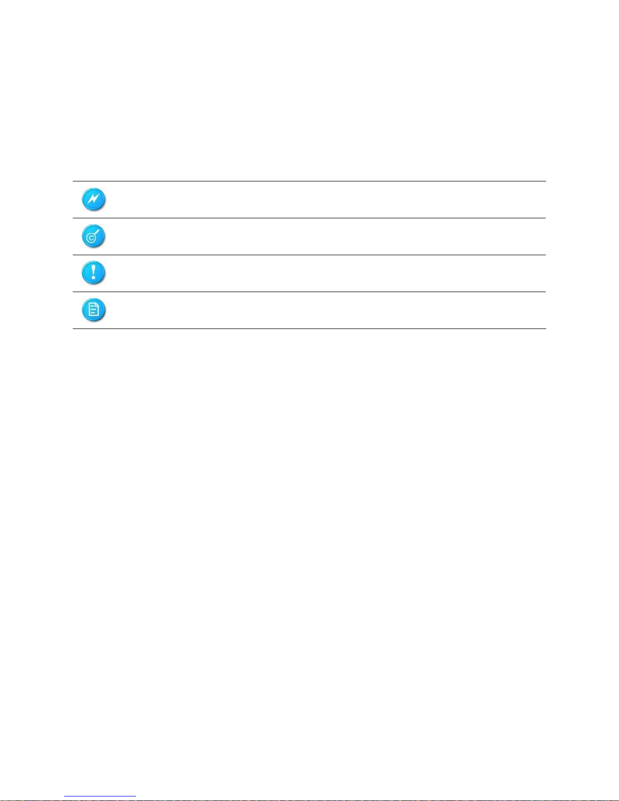
To properly perform tasks, take note of the following symbols used throughout this manual.
Warning:
Caution:
Important:
Information to prevent injury to yourself when trying to complete a
task.
Information to prevent damage to the components when trying to
complete a task.
Information that you must follow to complete a task.
Note:
Tips and information to aid in completing a task.
1
CiB‐9224V12UserManual
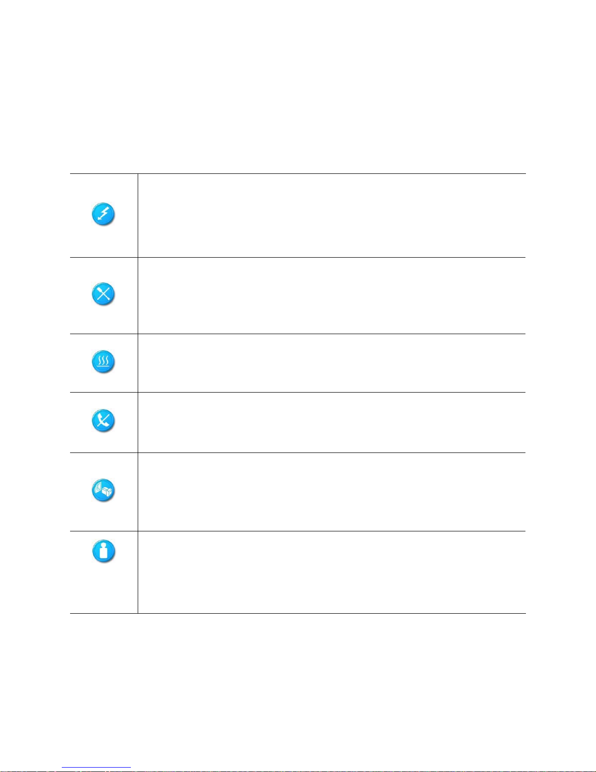
Safety Symbols
Before troubleshooting, you must be familiar with the safety information listed below. In order to avoid
any potential hazards, the following symbols may be placed on some components of
The shape and the color of symbols shown below are mainly for your reference. Please take the actual
shipment as standard.
Indicates the potential hazard of energy circuits or electric shock. To reduce
the risk of injury from electric hazards, do not open this enclosure.
Warning
indicates the presence of electric shock hazards. The enclosed area contains no
operator serviceable parts.
Indicates the potential hazard of electric shock. The enclosed area contains no user
of field serviceable parts. Do not open for any reason.
Warning: To reduce the risk of injury from electric shock hazards, do not open this
enclosure.
: Any surface or area of the equipment marked with this symbol
the system.
Weight in kg.
Weight in lb.
Indicates the presence of a hot surface or hot component.
Warning: To reduce the risk of injury from a hot component, allow the surface to
cool before touching it.
Any RJ45 receptacle marked with this symbol indicates a network interface
connection.
Warning: To reduce the risk of electric shock, fire, or damage to the equipment, do
not plug telephone or telecommunications connectors into this receptacle.
This symbol, on power supplies or systems, indicates that the equipment is supplied
by multiple sources of power.
Warning: To reduce the risk of injury from electric shock, remove all power cords to
completely disconnect power from the system.
This symbol indicates that the component exceeds the recommended weight for one
individual to handle safely.
Warning: To reduce the risk of personal injury or damage to the equipment, observe
local occupational health and safety requirements and guidelines for manual material
handling.
Safety Precautions
Observe the following safety precautions when you are connecting or disconnecting any device.
2

CiB‐9224V12UserManual
This is a non-consumer product. Professional know-how is recommended.
Operation Safety
Any operation on this system must be conducted by certified or experienced personnel.
Before operating, carefully read all included manuals.
Before using the system, take time to inspect all cables integrity and are properly
connected. When in doubt, please contact your dealer as soon as possible.
To avoid short circuits, keep all metal object (i.e. - Paper clips, screws, staples, etc.)
away from area which might carry electrical current.
Before opening chassis panels, make sure all power cords are unplugged.
Avoid dust, humidity, and extreme temperatures; place system on a stable surface.
Any defected components, do not try to fix it by yourself. Contact an authorized dealer.
Gloves are recommended when handling system to protect from cuts and scrapes.
When system is powered on, co mponents maybe hot. Proceed with caution. Check whether
fans are functioning properly.
Electrical Safety
Before installing or removing any components or cables, ensure all power cords for system
and attached devices are unplugged.
Antistatic wrist strap is recommended to prevent static discharge.
This product is equipped with three prong power cord and plug for user safety. Make sure your
electrical outlet is a properly grounded to avoid electric shock.
Nodes, adapters, and disk drives are sensitive to static electricity discharge. These devices are
wrapped in antistatic bags to prevent discharge that can cost damage. Take the following
If you have an antistatic wrist strap available, use it while handling the device.
Do not remove the device from the antistatic bag until you are ready to install the device
With the device still in its antistatic bag, touch it to a metal frame of the system.
Hold drives by the frame. Avoid touching the solder joints or pins.
precautions:
If you need to lay the device down while it is out of the antistatic bag, lay it on the antistatic bag. Before
picking it up again, touch the antistatic bag and the metal frame of the system
Handle the devices carefully to prevent permanent damage.
unit at the same time.
3

CiB‐9224V12UserManual
Battery Replacement Safety
This system is provided with an internal Lithium battery or battery pack. There is a danger of explosion
and risk of personal injury if the battery is incorrectly replaced or mistreated.
For more information about battery replacement or proper disposal, contact an authorized reseller or your
authorized service provider.
This system contains an internal Lithium Manganese Dioxide, or a Vanadium Pentoxide, or an
alkaline battery pack. There is risk of fire and burns if the battery pack is not handled properly. To
reduce the risk of personal injury:
Do not attempt to recharge the battery.
Do not expose to temperatures higher than 70°C.
Do not disassemble, crush, puncture, shorten external contacts, or dispose in fire or water.
Replace only with the spare parts designated for this product.
Batteries should not be littered along with the general household waste. Please use the public collection
system or return them to the supplier.
Laser Peripherals or Devices Safety
To avoid risk of radiation exposure and/or personal injury:
Do not open the enclosure of any laser peripheral or device.
Laser peripherals or devices are not user serviceable.
Return to manufacturer for servicing.
Intended Application Uses
This product was evaluated as Information Technology Equipment (ITE), which may be installed in offices,
schools, computer rooms, and similar commercial type locations. The suitability
product categories and environments (such as medical, industrial,
equipment), other than an ITE application, may require
further evaluation.
4
of this product for other
residential, alarm systems, and test

Site Selection
CiB‐9224V12UserManual
System is designed to operate in a typical office environment. Such as:
Clean, dry, and free of airborne particles (other than normal room dust).
Well-ventilated and away from sources of heat including direct sunlight and radiators.
Vibration or physical shock free environment.
Provided with a properly grounded wall outlet.
5

CiB‐9224V12UserManual
Regulatory and Integration Information
Regulatory Compliance Identification Numbers
For the purpose of regulatory compliance certifications and identification, this system is assigned a serial
number. This system serial number can be found on the product label, along
markings and information. When requesting certification
serial number. This serial number should not
be confused with the marketing name or model number.
information for this product, always refer to this
Product Regulatory Compliance
Worldwide Safety approvals can be supplied according to the requirements from Marketing or Customer.
Product Safety Compliance
This system complies with the following safety requirements:
with the required approval
Table i Product Safety Requirements IEC
60950-1 Safety of Information Technology Equipment
EN 60950-1 Safety of Information Technology Equipment Including Electrical Business Equipment,
European Committee for Electro technical Standardization
UL 60950-1 Safety of Information Technology Equipment
UL 94 Tests for Flammability of Plastic Materials for Parts in Devices & Appliances
GB4943
Safety of Information Technology Equipment
(CENELEC)
Product EMC Compliance
This product has been tested and verified to comply with the following electromagnetic compatibility
(EMC) regulations.
Communications Commission Notice
Part 15 of the Federal Communications Commission (FCC) Rules and Regulations has established Radio
Frequency (RF) emission limits to provide an interference-free radio
devices, including computers, generate RF energy
covered by these rules. These rules
place computers and related peripheral devices into two classes, A
incidental to their intended function and are, therefore,
and B, depending upon their intended installation. Class A devices are those that may reasonably be
expected to be
installed in a business or commercial environment. Class B devices are those that may
reasonably be expected to be installed in a residential environment (for example, personal computers). The
FCC requires devices in both classes to bear a label indicating the
well as additional operating instructions for the user.
frequency spectrum. Many electronic
interference potential of the device, as
6

CiB‐9224V12UserManual
The rating label on the device shows which class (A or B) the equipment falls into. Class A devices do
not have an FCC logo or FCC ID on the label. Class B devices have an FCC logo
label. Once the class of the device is determined, refer to the following
corresponding statement.
or FCC ID on the
Class A Equipment
This equipment has been tested and found to comply with the limits for a Class a digital device, pursuant
to Part 15 of the FCC Rules. These limits are designed to provide reasonable
interference when the equipment is operated in a commercial
uses, and can radiate radio frequency energy and,
instructions, may cause harmful interference
residential area is likely to cause
the interference at
personal expense.
harmful interference, in which case the user will be required to correct
if not installed and used in accordance with the
to radio communications. Operation of this equipment in a
environment. This equipment generates,
protection against harmful
Declaration of Conformity for Products Marked with the FCC Logo—United States
Only
This device complies with Part 15 of the FCC Rules Operation and is subject to the following two
conditions: (1) this device may not cause harmful interference, and (2) this device must
interference received, including interference that may cause undesired operation.
your product, please contact the supplier.
For questions regarding
To identify this product, refer to the Part, Series, or Model number found on the product.
accept any
European Union Notice
Products with the CE Marking comply with both the EMC Directive (89/336/EEC) and the LowVoltage Directive (73/23/EEC) issued by the Commission of the European Community.
Compliance with these directives implies conformity to the following European Norms (in brackets are
the equivalent international standards):
Table ii European Union EMC Requirements
EN55022 (CISPR 22) Electromagnetic Interference EN55024
(IEC61000-4-2,3,4,5,6,8,11) Electromagnetic Immunity
(IEC61000-3-2) Power Line Harmonics
EN61000-3-3 (IEC61000-3-3) Power Line Flicker
7
EN61000-3-2
 Loading...