

Page 1
DNS-2670
© DataON Storage, storage division of Area Data Systems.
User Manual
Version Dec. 2015
Page 2
Page 3

Contents
1 Introduction ................................................................................................................... …1
1.1
1.2
1.3
1.4
System Overview ................................................................................................................. …3
1.1.1
1.1.2
1.1.3
1.2.1
1.2.2
System Top View ............................................................................................................ ..3
Front View ...................................................................................................................... ..4
Rear View ....................................................................................................................... ..5
System LEDs Description .................................................................................................... …6
Front View LEDs ............................................................................................................ ..6
Back View LEDs ............................................................................................................. ..6
Key Parts for Replacement ................................................................................................... ..7
DNS-2670 Block Diagram ..................................................................................................... ..9
2 Hardware Operations ................................................................................................. ..12
2.1
2.2
2.3
2.4
2.5
2.6
2.7
Before You Start ................................................................................................................... ..13
Chassis Cover ..................................................................................................................... ..13
2.2.1
2.3.1
2.3.2
2.4.1
2.4.2
2.5.1
2.5.2
2.6.1
2.6.2
2.7.1
2.7.2
To remove the chassis cover ......................................................................................... 13
Power Supplies .................................................................................................................... ..14
To remove the power supply .......................................................................................... 14
To install the power supply ............................................................................................. 14
3.5” SATA/SAS HDDs .......................................................................................................... ..15
To remove a HDD........................................................................................................... 15
To install a HDD ............................................................................................................. 1 6
3.5” SATA/SAS HDD Backplanes ...................................................................................... ….18
To remove the backplane ........................................................................................... ….18
To install the backplane .............................................................................................. ….19
SAS IO Module .................................................................................................................. ….20
To remove the SAS I/O Module ................................................................................. ….20
To install the SAS I/O Module .................................................................................... ….20
Power Supplies .................................................................................................................... ..21
To remove the System Fans ...................................................................................... ….21
To install the System Fans ......................................................................................... ….22
Appendix A: Support ............................................................................................................... I
Before you Begin .................................................................................................................................. I
Troubleshooting Sequence ................................................................................................................... I
Installation Problem ........................................................................................................................... I
Troubleshooting External Connectors ............................................................................................... I
Troubleshooting System Boot Issues .............................................................................................. II
Appendix B: Specifications ................................................................................................. IV
Appendix C: China RoHS Regulations ................................................................................ V
Page 4

Chapter 1
Introduction
Page 5
Introduction
DNS-2670 Overview
Form Factor 4U 70-bay 3.5"
Drive Support 12Gb/s & 6Gb/s SAS 3.0 HDD and SSD
Drive Form Factor 3.5" Disk Device (2.5” Optional)
I/O Controller Dual Redundant 12Gb/s SAS 3.0 Controller Module
Host Interface Eight 12Gb/s SAS 3.0 SFF-8644 connections per I/O
SAS Expander Avago|LSI 12Gb/s SASx48 48-port expander
Controller Support 12Gb/s SAS HBA
Server Host Support Supports up to Eight Server/Host with eight host interface
Disk Drive 70 x 12Gb/s or 6Gb/s dual-ported SAS SSD & HDD
Enclosure Cooling Twelve Cooling Fan Module built-in Power Module
Power Supply 1023W Lite-On® 2+2 Redundant Power Supply
LED Indicators
Enclosure Dimensions 7” H x 19” W x 37.5” D
Weight Enclosure only: 110lbs with 70 drives: 275lbs
*Identify Enclosure *Power On & Activity *Drive Fault
*Identify Drive *Drive Rebuild
1
Failure Notification SCSI Enclosure Services (SES-3) over in-band & LEDs
1
Page 6
1 Introduction
The DNS-2670 configuration server system can support two SIM (SAS IO Module) nodes.
1.1
System Overview
1.1.1
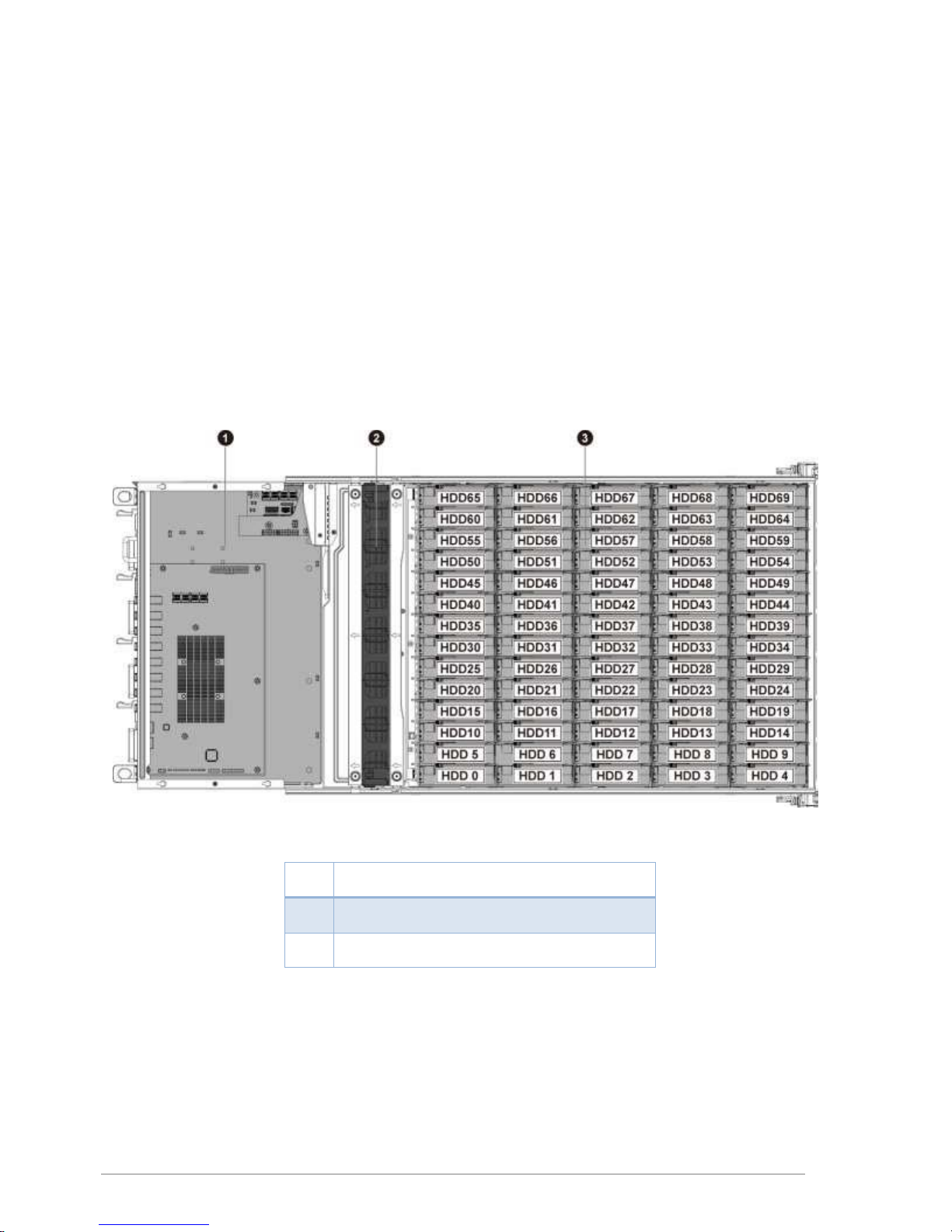
System To p View
1
2
3
2
Figure 1-1 System Top View
SIM Nodes 1&2 (Upper & Lower)
System Fan Module
HDDs for SIM Nodes 1&2
Page 7

Introduction
1.1.2
The front view of this DNS-2670 allows easy access to seven HDD backplanes. In addition,
seven backplanes with HDD LEDs are located on the front.
Front View
Figure 1-2 System Front View
1~7
10
HDD Backplane
HDD Activity LED
8
HDD Fail LED
9
HDD Online LED
3
Page 8
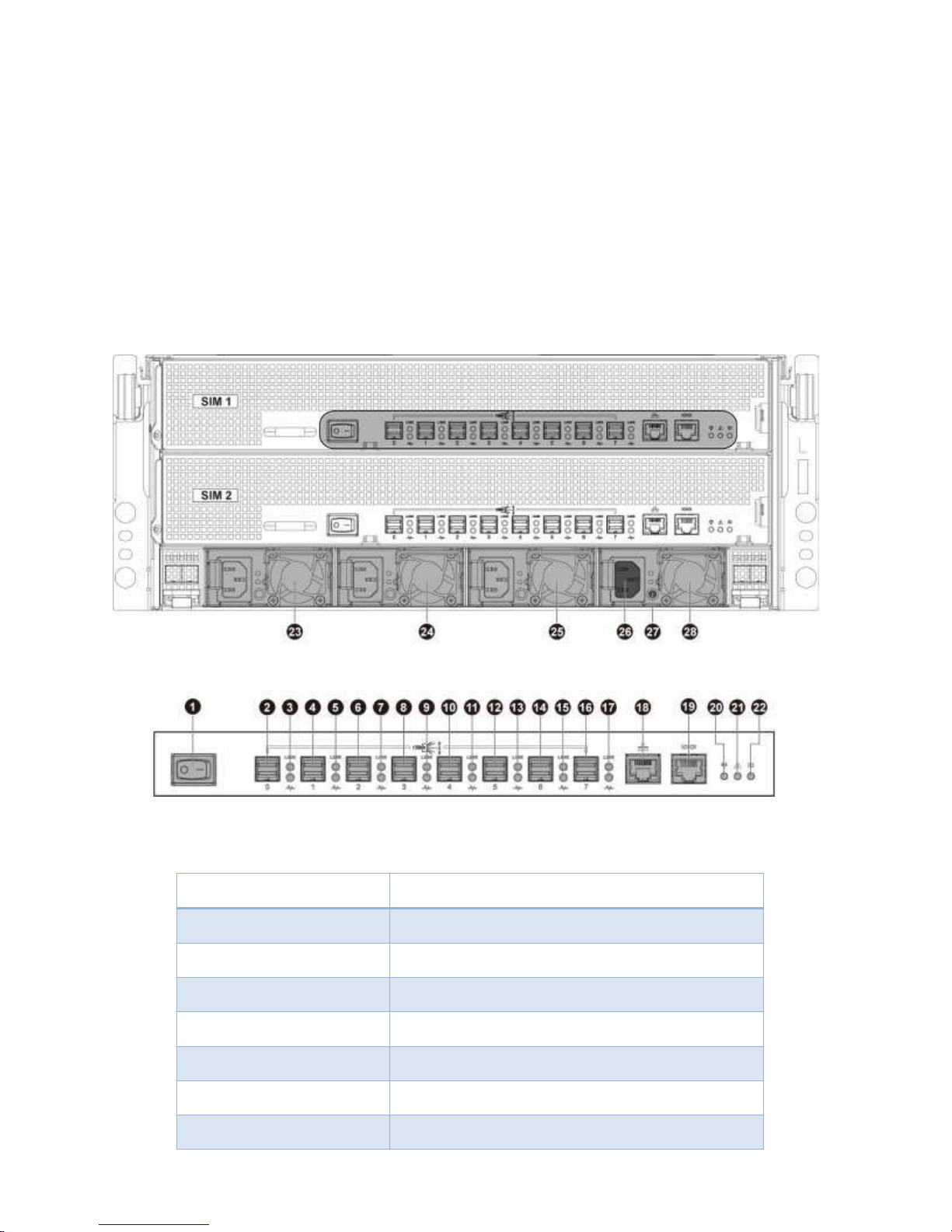
1.1.3 Rear View
The server back view includes the upper and lower SIM nodes, the back panels with system
buttons and LEDs, and four power supplies.
Figure 1-3 System Back View
1
2,4,6,8,10,12,14,16
3,5,7,9,11,13,15,17
18
19
20
21
22
Power Button (SW)
Mini-SAS HDD Connector
SAS Port Link/Status LED
Expander RJ45 Network Connector
Expander RJ45 UART Debug Connector
System Power LED
System Fail LED
System UID LED
4
Page 9
Introduction
1.2
1.2.1
The detailed LED information on the front is shown below:
23, 24, 25, 28
26
27
System LEDs Description
Front View LEDs
Power Supply
Power Connector
Power Supply Status LED
Table 1-1 LED Information
Type of LED Color Status Function
On SAS HDD is installed
No HDD is installed or SATA HDD is installed
but no data is accessed (RAID is optimal)
HDDs are accessing data (RAID is optimal)
or RAID is rebuilding.
HDD Activity
Green
Off
Blinking
On HDDs are failed or HDD backplane power fails.
HDD Fail
HDD Online
1.2.2
The detailed LED information on the back is shown below:
Back View LEDs
Red
Blinking HDD is locating or RAID is rebuilding.
On HDD is installed.
Green
Off No HDD.
Table 1-2 LED Information
Type of LED Color Status Function
Green: on, Red: off Mini-SAS HDD’s link successful.
Mini-SAS HDD
Link/ Status
LEDs
Green
/Red
Green: off, Red: off Mini-SAS HDD’s link failed.
Green: blinking, Red: off Mini-SAS HDD’s link with activities
Green: blinking, Red: on
Mini-SAS HDD’s link with activities but
physical link fail
System
Power LED
System Fail
6
Green
Red
On DC Power is on.
Off
On SIM is failed.
DC power has been turned off or no AC
power.
5
Page 10
LED
Off Power is off or disable by other SIM.
System UID
LED
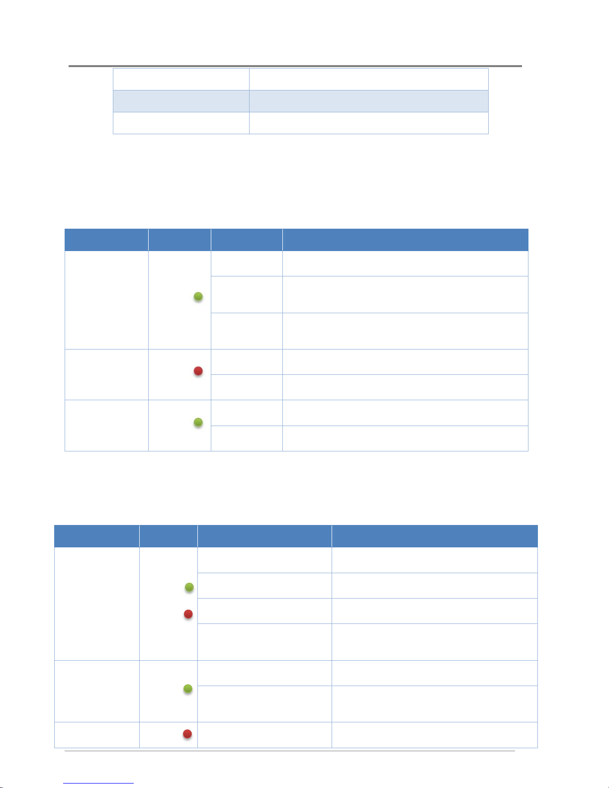
1.3
Key Parts for Replacement
Blinking SIM is identifying.
Blue
Off SIM is normal.
SAS I/O Module
Part #: DNS-2670-IOM
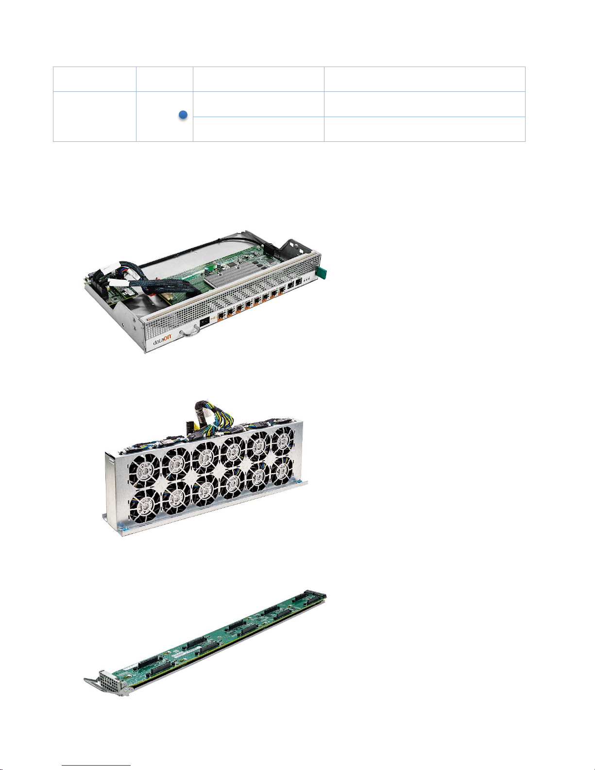
Fan Module
Part #: DNS-2670-CFK
Drive Blade
Part #: DNS-2670-DB10
7
Page 11

Hardware
2.5” Drive Tray
Part #: DNS-2670-DB2
3.5” Drive Tray
Part #: DNS-2670-DB3
Power Supply
Part #: DNS-2670-PSM
8
Page 12

1.4
DNS-2670 Block Diagram
9
Page 13

Hardware
Page 14

Chapter 2
Removing and Installing Hardware
11
Page 15

Hardware Operations
2 Hardware Operations
This chapter describes the hardware setup procedures that you have to perform when replacing
system components. It also gives detailed information on the internal components and how to
replace them.
The components shown in this chapter are mainly for your reference. Please take the
2.1
Take note of the following operations before you start to remove or install internal components.
12
actual shipment as standard.
Since the chassis weight with all the HDDs installed is over 100kg, it requires two more
persons to lift with suitable tools.
Before You Start
To reduce the risk of injury from electric shock, remove the power cord to completely
disconnect power from the system.
Moving the Power On/Off switch to the Off position does not completely remove power
from the system. Some portions of the power supply and some internal circuitry remain
active. Disconnect all power cords from the server to completely remove power from
the system.
Page 16

Hardware Operations
2.2
Chassis Cover
The DNS-2670 form factor designed for easy assembly and disassembly, making the
replacement of internal components very convenient.
Reminder
Before you remove or install the top front cover chassis c o v e r , please follo w the step b elow:
Step 1: Make sure all of the SIM nodes are not turned on and the server is not connected to
AC power.
2.2.1
To remove the chassis cover
Release the screw on the top front chassis cover.
Slide the front cover horizontally to the front and remove it along the direction of the arrow.
Figure 2-2 Removing the Top Front Chassis Cover
13
Page 17

Hardware Operations
2.3
Power Supplies
This server is designed with four 1200W power supplies.
Reminder
Before you remove or install the power supply, please follow the steps below:
Step 1: Disconnect all necessary cables.
2.3.1
Press the retaining clip to the right side along the direction of the arrow.
At the same time, pull out the power supply. (The power supply takes considerable force to
To remove the power supply
Pull down the handle.
remove.)
Figure 2-8 Removing the Power Supply
2.3.2
To install the power supply
Insert the replacement power supply firmly into the bay. The retaining clip should snap.
Connect the AC power cord to the replacement power supply.
Figure 2-9 Installing the Power Supply
14
Page 18

Hardware Operations
2.4
3.5” SATA/SAS HDDs
DNS-2670 can support 70 x 3.5” hot-pluggable SATA/SAS HDDs.
Reminder
Before you remove or install the 3.5” SATA/SAS HDDs, please follow the steps below:
Step 1: Make sure all of the SIM nodes are not turned on and the server is not connected
to AC power.
Step 2: Remove the chassis cover. To remove the chassis cover, see “0
cover
To remove the chassis
Step3: Disconnect all necessary cables.
Take note of the drive tray orientation before sliding it out.
The tray will not fit back into the bay if inserted incorrectly.
.
2.4.1
To remove a Disk
Push the release button.
Pull the lever open.
Slide the Disk assembly out of the Disk bay.
Figure 2-10 Removing the Disk Assembly
Loosen the four screws that secure the Disk.
Lift the Disk out of the Disk tray.
15
Page 19

Hardware Operations
2.4.2
To install a Disk
Place the Disk to the Disk tray.
Figure 2-11 Removing the Disk
Figure 2-12 Placing the Disk to the Disk Tray
Secure the Disk to the Disk tray with four screws.
Carefully insert the Disk assembly into the Disk bay with the lever lifted until it completely
enters the Disk bay.
Push the lever back in place.
16
Figure 2-13 Fastening the Screws
Page 20

Hardware Operations
Figure 2-14 Installing the Disk Assembly
Make sure that the Disk is connected to the Disk connector on the backplane.
17
Page 21

Hardware Operations
2.5
3.5” SATA/SAS HDD Backplanes
DNS-2670 (SIM) 70-70 configuration system supports seven 3.5” SATA/SAS HDD backplanes,
which support up to 70 x 3.5” SATA/SAS HDDs in the system.
Reminder
Before you remove or install the 3.5” SATA/SAS HDD bakcplane, please follow the steps
below:
Step 1: Make sure all of the SIM nodes are not turned on and the server is not connected
to AC power..
Step 2: Remove the chassis cover. To remove the chassis cover, see “0
To remove the chassis
Step 3: Remove the HDDs. To remove the HDDs, see “2.5.1 To remove a HDD”.
Step 4: Disconnect all necessary cables.
cover
.
2.5.1
To remove the backplane
Remove the screw that secures the backplane assembly.
Figure 2-15 Loosening the Screw
Pull down the backplane assembly handle.
Remove the backplane assembly out of the cage.
18
Page 22

Hardware Operations
Figure 2-16 Removing the Backplane Assembly
Loosen the screws that secure the backplane.
2.5.2
To install the backplane
Reverse the steps above to install the backplane.
19
Page 23

Hardware Operations
2.6
SAS IO Module
Reminder
Before you remove or install the SIM node, please follow the steps below:
Step 1: Make sure the SIM node is not turned on.
Step 2: Disconnect all necessary cables.
Please make sure the top rear chassis cover is installed when removing or installing
any SIM nodes to prevent the docking board connectors on the interposer board
2.6.1
Slide the SIM node out of the chassis by using the handle.
from damage.
To remove the SIM node
Press the retaining latch.
2.6.2
Push the SIM node into the chassis until it’s completely seated in place.
20
To install the
SIM
node
Figure 2-18 Removing the Node
Figure 2-19 Installing the SIM Node
Page 24

Hardware Operations
2.7 System Fans
Subdividing the SIM board area and the backplane area is a metal cage that holds the system
fans. This server contains 12 system fans which are located inside the chassis. These system
fans maintain the ideal temperature for the SIM boards, backplanes and disk drives.
The sequence of system fans is shown below for your reference:
Figure 2-20 System Fan Sequence
Reminder
Before you remove or install the system fans, please follow the steps below:
:
Step 1
Make sure all of the SIM nodes are not turned on and the server is not connected to
AC power.
Step 2
Step 3: Disconnect all the necessary cables.
:
Remove the chassis cover. To remove the chassis cover, see “0
To remove the chassis
cover
2. 7 . 1 T o remove the system fans
Loosen the screws that secure the interposer-board assembly support.
Remove the interposer-board assembly support out of the chassis.
Loosen the screws that secure the system fan cage.
Remove the system fan cage out of the chassis along the direction of the arrow.
Figure 2-21 Removing the System Fan Cage
21
Page 25

Loosen the screws that secure the back cover.
Remove the back cover out of the system fan cage.
Figure 2-22 Removing the Back Cover
Remove the single fan from the system fan cage.
Figure 2-23 Removing the System Fan
2. 7 . 2 T o install the system fans
Reverse the steps above to install the system fans.
When installing the system fan cage into the chassis, the arrows on the system fan
cage must point to the direction of power supplies.
When installing the system fans, recommend to install them in the order of system
fan 1 and system fan 12 from left to right.
22
Page 26

Appendix
Appendix
Page 27

Appendix
Appendix A: Support
Page 28

Appendix
Before you Begin
Before removing the chassis cover, disconnect all power. Unplug the AC power
Make sure you have a stable, clean working environment. Dust and dirt can get into computer
components and cause a malfunction. Many of the screws on the server are different sizes;
use containers to keep screws and small components separated.
Adequate lighting and proper tools can prevent you from accidentally damaging internal
components. Most of the following procedures require only a few simple tools, including the
following:
cord; disconnect all peripherals, and all LAN lines.
Philips screwdriver
flat-tipped screwdriver
set of jewelers screwdrivers
grounding strap
anti-static pad
Troubleshooting Sequence
Installation Problem
Perform the following checks if you are troubleshooting an installation problem:
Check all cable and power connections (including all rack cable connections).
Unplug the power cord, and wait one minute. Then reconnect the power cord and try
again.
Remove all added options, one at a time, and try to power up the system. If after
removing an option the server works, you may find that it is a problem with the option or
a configuration problem between the option and the server. Contact the option
vendor for assistance.
If the system doesn’t power on, check the LED display. If the power LED is not on, you may
not be receiving AC power. Check the AC power cord to make sure that it is securely connected.
Troubleshooting External Connectors
Loose or improperly connected cables are the most likely source of problems for the system,
monitor, and other peripherals (such as a printer, keyboard, mouse, or other external device).
Ensure that all external cables are securely attached to the external connectors on your
system. See 1.1 System Overview for the front- and back-panel connectors on your system.
Troubleshooting System Boot Issues
This document lists troubleshooting tips if your server does not boot up properly.
Page 29

Appendix
Contents:
System Does Not Boot up at First Integration
Power Connector Not Plugged In Power
Supply and Chassis Issues Cable
Issues
Electrical Short or Overload
System Used to Boot up and Now Does Not
New Drive was Installed
Examples of troubleshooting system boot issues
Fans don't spin when power button pressed
System Does Not Boot up at First Integration
Board-to-Board Power Connector Not Plugged In
Check the connection between the SIM board and the docking board, and the connection
between the docking board and the middle plane. If one of them is not connected fully in place,
the system will not boot up. Please ensure that they are fully connected.
Power Supply and Chassis Issues
No boot situations can be caused by any of the following power supply, chassis or fan issues:
Verify that your chassis and power supply is appropriate for the frequency and the SIM
boards you have.
Verify that the power supply has the capacity to power all the devices used in your
system.
Ensure the power cord is firmly connected to the power supply and the AC outlet.
If the power supply or the AC outlet has an on/off switch, make sure that it is on.
Cable Issues
No boot situations can be caused by any of the following cabling issues:
Make sure the drive ribbon cables inside the computer are attached correctly and
securely.
Check that the cables connecting the chassis back panel to the SIM boards are
plugged in properly to the onboard headers.
Electrical Short or Overload
An electrical short or overload may cause a system not to boot.
Check for shorts and overloads by removing non-essential items such as extra controller
cards. Keep only the SIM boards, power supply installed. If the system boots, it is possible
there is a short or overload with one of the components that you removed or one of those
components is faulty. Replace each of non-essential items one at a time until you isolate
which one is causing the problem.
Page 30

Appendix
If the problem occurs even after removing the non-essential components, the problem has to
be with the SIM boards, power supply.
System Used to Boot up and Now Does Not
Changes to your computer's configuration can cause your system to not boot properly.
New Drive was Installed
If you added a new drive and now the system won't boot:
Make sure the new drive is supported for your SIM boards. To find the tested hard
drive list for your board, please contact your field representatives.
Make sure all drive cables are properly connected.
Make sure the correct power cable is connected to the new drive.
Make sure other devices and cables inside the chassis were not disturbed or loosened
when you added the new drive.
Examples of troubleshooting system boot issues
Below are some examples on how to troubleshoot system boot issues.
Fans don’t spin when power button pressed
Is at least one power supply fan spinning?
If it is yes, there is good power to the modules. Verify all required power cables are
correctly plugged into the SIM boards. Verify back panel cables are fully seated.
If it is no, there is potential lack of clean power to the module. Swap power cable. Try
different wall circuit or port on UPS.
Appendix B: Specifications
Dimensions
System Fan 12 x 6038 fans
Power Supply 4 x1200W power supplies
Weight Maxi-weight: 102kg
Temperature
Humidity
Voltage 100/240VAC input, 50/60Hz
Current 9.5/5A
Height: 174.75mm
Width: 430mm
Length: 950mm
Operating System: +5C ~ +35C
Non-operating System: -40C ~ +70C
Operating System: +20% ~ +80%
Non-operating System: +10% ~ +90%
Page 31

Page 32

Appendix C: China RoHS Regulations
Appendix
Figure I China RoHS Regulations
 Loading...