

Page 1
DNS-1640
User Manual
2U 24 Bays 6Gb/s SAS JBOD
Dual-path, Dual I/O
Copyright © 2014- DataON Storage. All rights reserved.
Version QS0003
www.dataonstorage.com
Page 2

1
Copyright
This publication, including all photographs, illustrations and software, is protected under international copyright
laws, with all rights reserved. Neither this manual, nor any of the material contained herein, may be reproduced
without the express written consent of the manufacturer.
Copyright © 2011 DataON Storage Inc.
Trademarks
All product names used in this manual are the properties of their respective owners and are acknowledged.
Disclaimer
The information in this document is subject to change without notice. The manufacturer makes no representations
or warranties with respect to the contents hereof and specifically disclaim any implied warranties of merchantability
or fitness for any particular purpose. Furthermore, the manufacturer reserves the right to revise this publication
and to make changes from time to time in the content hereof without obligation of the manufacturer to notify any
person of such revision or changes.
Safety Measures
Computer components and electronic circuit boards can be damaged by discharges of static electricity. Working on
computers that are still connected to a power supply can be extremely dangerous. Follow these guidelines to avoid
damage to the DNS 1640 or injury to yourself.
• Always disconnect power when carrying out work inside the unit.
• If possible, wear a grounded wrist strap when carrying out work inside the unit. Alternatively,
discharge any static electricity by touching the bare metal chassis of the unit case, or the bare
metal body of any other grounded appliance.
• Hold electronic circuit boards by the edges only. Do not touch the components on the board unless it is necessary to do so. Do not flex or stress the circuit board.
• Leave all components inside the static-proof packaging until you are ready to install the component.
Equipment Location
This equipment should only be accessed by SERVICE PERSONNEL or by USERS who have been instructed about
the reasons for the restrictions applied to the location. Access is through the use of a TOOL or lock and key, or
other means of security, and is controlled by the authority responsible for the location.
About this Guide
This guide describes how to setup and power on the DNS 1640 6Gb/s SAS JBOD system. This guide is intended for
trained personnel only.
Page 3
DNS-1640 User Manual
2
Package content
The DNS-1640 box contains the following items:
• DNS-1640 Storage un it ( 1)
• Power cord (2)
• CD with user manual and drivers (1)
• Universal Rail Kit for DNS-1640 (1)
• HDD Screws(96)
System requirements
• Servers with supported HBA/Raid adapter, refer to DNS-1640 support matrix reference
for complete listing of supported adapt e r s.
• SFF-8088 to SFF -8088 SAS cable(s).
Model
Model# DNS-1640SM DNS-1640DM DNS-1640S DNS-1640D
Hard Drive Type SATA/SSD SATA/SSD SAS/SSD SAS/SSD
SAS I/O Module 1 2 1 2
DNS-BJMB
2.5” Interposer
12 12 0 0
Technical Support
Contact your system supplier.
Page 4
3
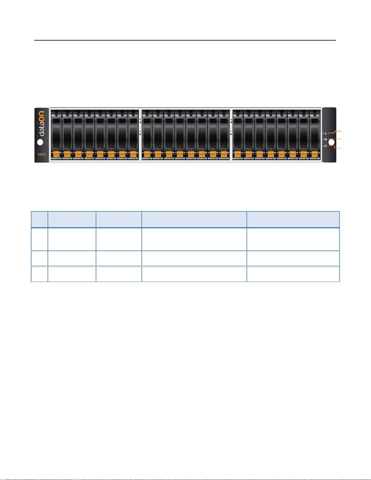
DNS-1640 Overview
LEDs on the Storage Enclosure
DNS-1640 User Manual
1
2
3
No Component Color Lights On Lights Off
1 Fault LED Amber A component within the storage en-
closure needs attention.
2 Locate LED Flashing Blue Identifies a storage enclosure Normal
3 Power Green Power On Power Off
Normal
Page 5
DNS-1640 User Manual
4
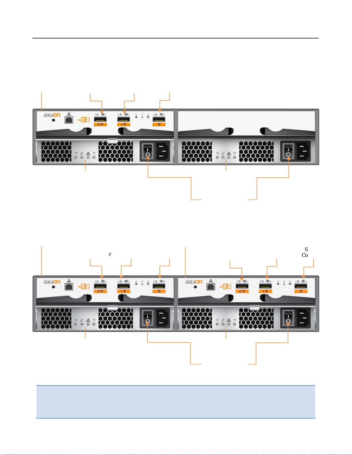
Power Connector
Power Supply
SIM
Board #1
Power Supply
Power Connector
SIM
Power Supply
DNS-1640 (Single SIM) Rear View
SAS #2
Connector
Module 1
SAS #1
Connector
SAS #3
Connector
Module 2
DNS-1640 (Dual SIM) Rear View
SIM
Board #1
SAS #2
Connector
SAS #1
Connector
Connector
SAS #3
Board #2
SAS #2
Connector
SAS #1
Connector
SAS #3
Connector
Important:
Power Supply
Module 1
Module 2
Note the direction of the power supply unit. Insert the power supply with the
right direction.
All SAS IN & OUT connectors are SFF-8088
Page 6
DNS-1640 User Manual
5
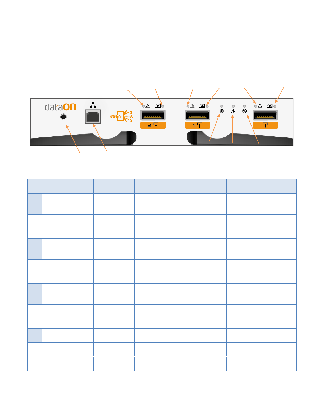
1
3 2 4 6 5
DNS-1640 SIM Board LED Description
LED ON SIM Board
Consoles for factory use only 7
No Component Color Lights On Lights Off
1 SAS #2 Fault Amber PHY connection cannot es tab-
lished correctly
2 SAS #2 Active Green PHY connection established
correctly
3 SAS #1 Fault Amber PHY connection cannot estab-
lished correctly
4 SAS #1 Active Green PHY connection established
correctly
5 SAS #3 Fault Amber PHY connection cannot estab-
lished correctly
6 SAS #3 Active Green PHY connection established
8
No error had occurred
No connection
No error had occurred
No connection
No error had occurred
No connection
9
correctly
Locate LED
7
8 SIM Fault Amber Fault exist Normal
9 SIM Power Green Power On Power Off
Flashing Blue Identifies SIM Normal
Page 7

DNS-1640 User Manual
6
DNS-1640 PSM Board LED Description
1
No Component Color Lights On Lights Off
1 DC Power Green DC Power On No DC Power
Locate LED
2
3 PSM Fault Amber Fault exist Normal
4 AC Power Green AC Power On No AC Power
2 3
Blue Identifies Power Module Normal
4
Page 8

7
Disk Drives Front LED and Tray
HDD Tray
1
DNS-1640 User Manual
Optional DNS-BJMB
9252 6Gb/s SAS
Interposer for 2.5”
SATA SSD/HDD
Release button
Disk Tray Handle
No Component Color Description
1 HDD Activity LED Solid Green SAS HDD is ready (SATA will be blank)
Blinking Green Spin up /Accessing
2 HDD status Blank HDD Ok
Blinking Blue Identify HDD
Solid Orange HDD fault
Blinking Orange & Blue
RAID Rebuilt
Blinking Blue HDD is ready to remove (HDD Activity LED will be blank)
Page 9

DNS-1640 User Manual
8
SAS HDD
SATA HDD
SAS HDD
Install/Replace HDD
Before You Begin
It is not recommend mixing different RPM SAS and SATA HDD in the same DNS-1640 system. If you have to,
please use the following figures below to plan where you will be placing the disk drives.
These figures represent fully-loaded DNS-1640 system with HDD.
However, the same guidelines apply even if you are f i l li ng some of the HDD slots with blank disk trays in the mix-
ing HDD setting.
Recommended Mixing SAS & SATA HDD Configurations
nsupported SAS & SATA HDD Combinations
U
Do not include SAS and SATA
HDD in the same section!
SATA HDD
Page 10

9
Follow these steps below to Install/Replace HDD i n the disk tray.
Step 1
DNS-1640 User Manual
a) Pre
b) R
ss the release button and open the disk tray handle.
emove HDD carrier by pulling the disk tray handle out.
Page 11

10
S
tep 2
DNS-1640 User Manual
Insert the HDD inside the tray and tighten the four 6/4 screws on the SATA/SAS disks.
S
ATA disk SAS disk
Interposer for SATA
Important:
If using SATA HDD, please make sure having DNS-BJMB Interposer card installed
on the back of HDD
Page 12

DNS-1640 User Manual
11
Step 3 Slide in the HD tray back in the disk slot and close the disk tray handle.
S
tep 4 Repeat Step 1 through 3 if you wish to install more HDD into the DNS-1640 storage.
Page 13

12
Before You Begin
DNS-1640 User Manual
Important:
onfirm that there is adequate power at your facility to support the high-availability features of the system.
C
It is recommended to connect each power connector to separate power circui t.
If necessary refer to the documentations shipped with the 6Gb/s SAS HBA/RAID card for hardware and
driver installation instructions
There are different types of SAS Cables in the market, make sure you order the right one for DNS-1640.
For DNS-1640, it all uses SFF-8088 to SFF-8088 SAS Cable when connecting DNS-1640 to host and when
daisy chain to another DNS-1640.
SFF-8088 to SFF-8088 SAS Cable
Before you set up the DNS 1640 system, be sure your facility meets the following
conditions.
Page 14

DNS-1640 User Manual
13
2nd DNS-1640
3rd DNS-1640
Setting up DNS-1640 System
Connection type 1(Single SIM)
This illustration shows one host with a HBA/RAID card connected to four DNS-1640 with single SIM.
SFF-8088 to SFF-8088 SAS Cable
1st DNS-1640
4rh DNS-1640
Page 15

DNS-1640 User Manual
14
RAID/HBA CARD
1st DNS-1640
2nd DNS-1640
Connection type 2(Dual SIM)
s illustration shows one host with a HBA/RAID card connected to four DNS-1640 with dual SIM.
Thi
Important:
SFF-8088 to SFF-8088 SAS Cable
Not All HBA/RAID card support this type of connection please refers to DNS-1640
support matrix reference for complete listing of supported dual port HBA/RAID
cards.
3rd DNS-1640
4th DNS-1640
Page 16

15
Connecting Power to DNS-1640
Power Strip 1
Power Strip 2
DNS-1640 User Manual
Important:
1. Ensure the cabinet circuit breakers are in OFF position.
2. Connect the two provided power cables from the DNS-1640 to cabinet power strips.
3. Lock down the two power cord latch.
DNS-1640 is recommended to be installed in Dual power strip cabinets.
4. Connect the power cables from the cabinet to separate power circuits in your facility.
Note: Cabinet is not included in the package. Only the universal rails kit for the cabinet ar
ovided.
pr
e
Page 17

16
Power on the DNS-1640
DNS-1640 User Manual
1. Ve
2. Turn on both circuit breakers on cabinet.
3. Make sure that power-on LED on all DNS-1640 are steady blue.
4. Power on the host lastly.
Important:
rify that all connections are correct.
Please make sure power on all DNS-1640 first before the server
Page 18

17
Features and Specifications
DNS 1640 is a high-availability, cost-effective
2U SAS (Serial Attached SCSI) to SAS (Serial
Attached SCSI) JBOD, which provides 24 pcs
2.5” hard drive carriers to support various
types of hard drive, including 6Gb/s SAS hard
drive, and 6Gb/s SATA III hard drive with interposer card. In addition to 24 pcs hard drive
carriers, DNS-1640 system supports two 550W
Full Redundant Power Supplies and two SIM
modules.
High Reliability: Redundant SIM modules,
power supplies modules design secure “No
Single-Point Failure”. Active-Active Dual
6Gb/s SAS I/O Module Architecture, hotswappable hard disk, and dual SAS and SATA
II paths with Interposer Card ensure that DNS1640 has high reliability and achieves 24x7
availability.
High Scalability: Each DNS-1640 system supports a maximum of 24 6Gb/s SAS/SATAIII
hard disks per system, and up to 96 drives by
daisy-chaining JBOD.
Features:
Redundant SIM Modules and Power Supplies
Active-Active Dual 6GB/s
chitecture
Support full path fail-over function which pro-
vides data redundancy
Support Drive Auto Detection and Hot Swap
Integrated RAID card management too l via
SES2
Connectivity Features:
Two 6Gb/s SAS-IN ports in each SIM module
provides host connectivity
Support up to 96 drives by daisy-chaining
JBODs.
Connected and managed by RAID controller
Connect to 6Gb/s SAS Expander
Support Direct Attach
Support daisy-chain of JBODs
DNS-1640 User Manual
SAS I/O Module Ar-
High Flexibility: DNS-1640 system supports
both SAS and SATA disks depending on customer’s needs. This feature provides the most
cost-effective storage pools for different kinds
of data and provides a better management
for ILM (Information Life Cycle Management)
applications.
High Performance: The Active-Active Dual
6Gb/s SAS I/O Module Architecture ensures
high system performance
.
Page 19

18
Host Interface:
Hard Disk Interface:
Redundant, Hot Swappable Components:
Form Factor:
(H)
Management Features:
AC Power:
Operating Environment:
Electromagnetic Emissions Standards :
Safety Standards:
Two 6Gb/s SAS-In ports on each SIM module
One 6Gb/s SAS-Out ports on each SIM module
24 x dual ported SAS (6Gb/s) or SATAII hard disks with DNS-BJMB
9252 6Gb/s SAS interposer (6Gb/s)
Up to a maximum of 24 disks per JBO D .
By daisy-chaining JBODs, up to 96 disk drives supporte d
2 SIM Modules
2 Power Supply Modules
up to 24 SAS/SATAII hard disks
Internal Bays: 24 2.5” Hard Disks
Rack Mount: 18.5 inch (D)
Dimensions: The chassis d imensions measured at 17.5” (W) X 6.875”
X 18.5” (D) (Sheet metal case only, not including bezel and rear module
handle).
Intergated with RAID Card management tool via SES2
LED Indicators for SM Modules, Hard
Drives, Power Supplies and FA N Status.
DNS-1640 User Manual
Input Voltage: 100-240 V AC
Input Frequency: 50-60Hz
Output Power: 550W
Operating Temperature: 0 to 35 degree Celsius
Operating Humidity: 20% to 95% (non-condensing)
Altitude: -50 to 10,000 feet
Shock: 31G @ 2.6ms, ½ sine wave pulse
Vibration: 0.25G @ 3Hz to 200Hz
FCC- class A under 3dB
CE- Specifically requiremen ts in effect July 1, 2001
UL/CUL: for U.S. with Canada
 Loading...