

DataON DNS-1640, DNS-1640D, DNS-1640SM, DNS-1640DM, DNS-1640S User Manual
DNS-1640
User Manual
2U 24 Bays 6Gb/s SAS JBOD
Dual-path, Dual I/O
Copyright © 2014- DataON Storage. All rights reserved.
Version QS0003
www.dataonstorage.com

1
Copyright
This publication, including all photographs, illustrations and software, is protected under international copyright
laws, with all rights reserved. Neither this manual, nor any of the material contained herein, may be reproduced
without the express written consent of the manufacturer.
Copyright © 2011 DataON Storage Inc.
Trademarks
All product names used in this manual are the properties of their respective owners and are acknowledged.
Disclaimer
The information in this document is subject to change without notice. The manufacturer makes no representations
or warranties with respect to the contents hereof and specifically disclaim any implied warranties of merchantability
or fitness for any particular purpose. Furthermore, the manufacturer reserves the right to revise this publication
and to make changes from time to time in the content hereof without obligation of the manufacturer to notify any
person of such revision or changes.
Safety Measures
Computer components and electronic circuit boards can be damaged by discharges of static electricity. Working on
computers that are still connected to a power supply can be extremely dangerous. Follow these guidelines to avoid
damage to the DNS 1640 or injury to yourself.
• Always disconnect power when carrying out work inside the unit.
• If possible, wear a grounded wrist strap when carrying out work inside the unit. Alternatively,
discharge any static electricity by touching the bare metal chassis of the unit case, or the bare
metal body of any other grounded appliance.
• Hold electronic circuit boards by the edges only. Do not touch the components on the board unless it is necessary to do so. Do not flex or stress the circuit board.
• Leave all components inside the static-proof packaging until you are ready to install the component.
Equipment Location
This equipment should only be accessed by SERVICE PERSONNEL or by USERS who have been instructed about
the reasons for the restrictions applied to the location. Access is through the use of a TOOL or lock and key, or
other means of security, and is controlled by the authority responsible for the location.
About this Guide
This guide describes how to setup and power on the DNS 1640 6Gb/s SAS JBOD system. This guide is intended for
trained personnel only.
DNS-1640 User Manual
2
Package content
The DNS-1640 box contains the following items:
• DNS-1640 Storage un it ( 1)
• Power cord (2)
• CD with user manual and drivers (1)
• Universal Rail Kit for DNS-1640 (1)
• HDD Screws(96)
System requirements
• Servers with supported HBA/Raid adapter, refer to DNS-1640 support matrix reference
for complete listing of supported adapt e r s.
• SFF-8088 to SFF -8088 SAS cable(s).
Model
Model# DNS-1640SM DNS-1640DM DNS-1640S DNS-1640D
Hard Drive Type SATA/SSD SATA/SSD SAS/SSD SAS/SSD
SAS I/O Module 1 2 1 2
DNS-BJMB
2.5” Interposer
12 12 0 0
Technical Support
Contact your system supplier.
3
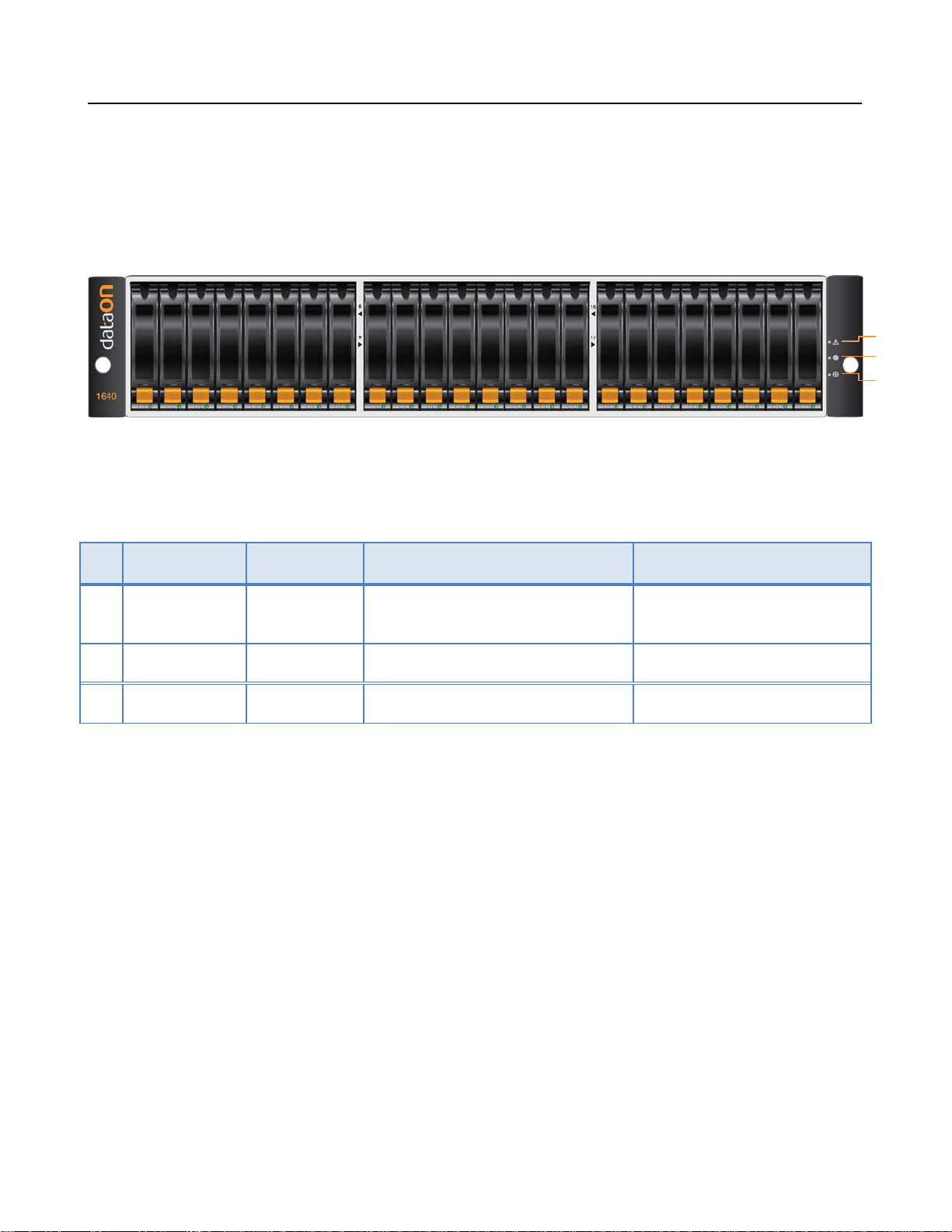
DNS-1640 Overview
LEDs on the Storage Enclosure
DNS-1640 User Manual
1
2
3
No Component Color Lights On Lights Off
1 Fault LED Amber A component within the storage en-
closure needs attention.
2 Locate LED Flashing Blue Identifies a storage enclosure Normal
3 Power Green Power On Power Off
Normal
DNS-1640 User Manual
4
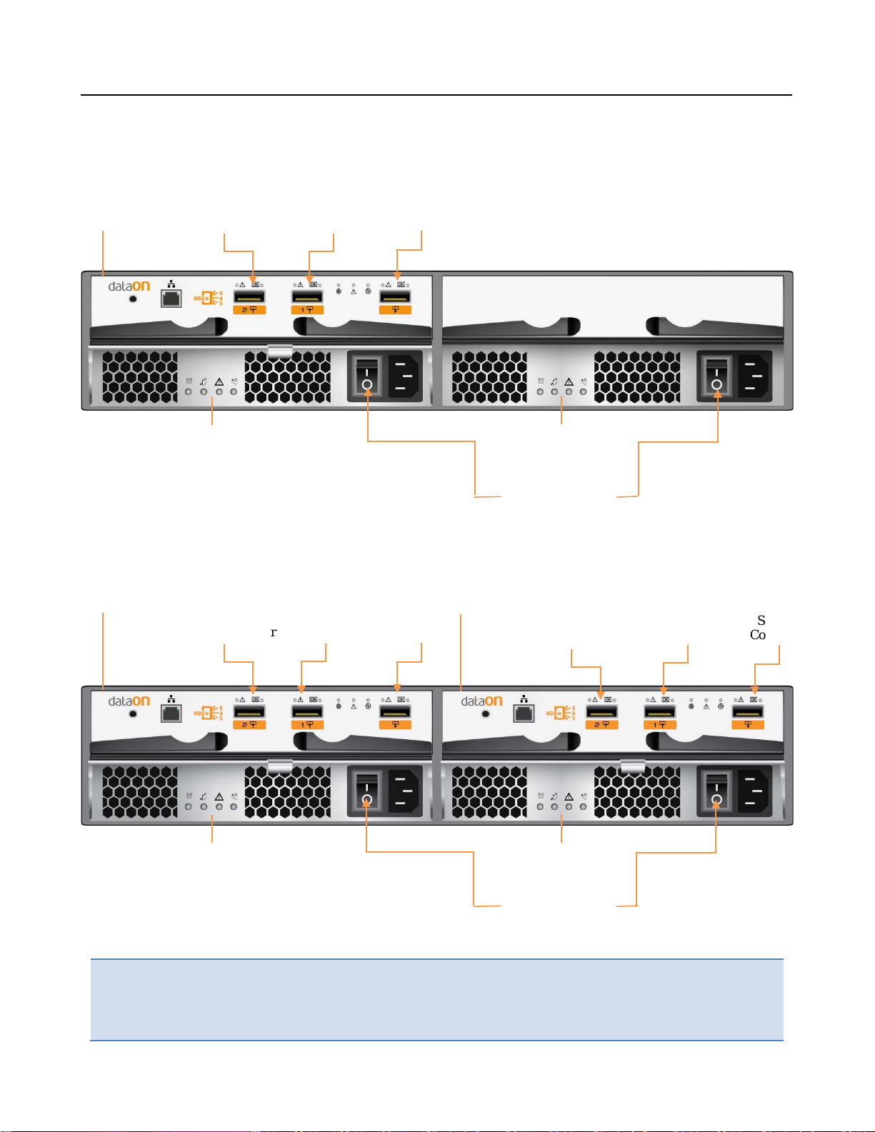
Power Connector
Power Supply
SIM
Board #1
Power Supply
Power Connector
SIM
Power Supply
DNS-1640 (Single SIM) Rear View
SAS #2
Connector
Module 1
SAS #1
Connector
SAS #3
Connector
Module 2
DNS-1640 (Dual SIM) Rear View
SIM
Board #1
SAS #2
Connector
SAS #1
Connector
Connector
SAS #3
Board #2
SAS #2
Connector
SAS #1
Connector
SAS #3
Connector
Important:
Power Supply
Module 1
Module 2
Note the direction of the power supply unit. Insert the power supply with the
right direction.
All SAS IN & OUT connectors are SFF-8088
DNS-1640 User Manual
5
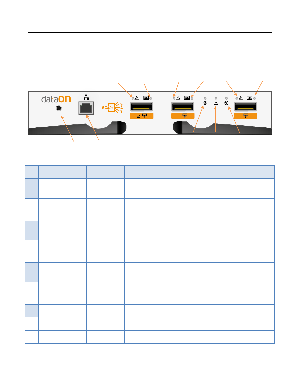
1
3 2 4 6 5
DNS-1640 SIM Board LED Description
LED ON SIM Board
Consoles for factory use only 7
No Component Color Lights On Lights Off
1 SAS #2 Fault Amber PHY connection cannot es tab-
lished correctly
2 SAS #2 Active Green PHY connection established
correctly
3 SAS #1 Fault Amber PHY connection cannot estab-
lished correctly
4 SAS #1 Active Green PHY connection established
correctly
5 SAS #3 Fault Amber PHY connection cannot estab-
lished correctly
6 SAS #3 Active Green PHY connection established
8
No error had occurred
No connection
No error had occurred
No connection
No error had occurred
No connection
9
correctly
Locate LED
7
8 SIM Fault Amber Fault exist Normal
9 SIM Power Green Power On Power Off
Flashing Blue Identifies SIM Normal
 Loading...