

Data Modul IX57QM, IX55HM User Manual
Data Modul AG - www.data-modul.com
User Manual
*92.*9).
*OUFMÚ2.).#("$PSFJJJ
.PCJMF.JOJ*59.PUIFSCPBSE
Version March 201

IX57QM/IX55HM
2
Contents
Safety Information .......................................................................................................... 4
Technical Support ............................................................................................................ 5
Conventions Used in This Guide .................................................................................... 5
Packing List ....................................................................................................................... 6
Revision History ............................................................................................................... 7
Specifications Summary .................................................................................................. 8
Block Diagram ................................................................................................................. 11
Production Introduction ............................................................................................... 13
1.1 Before you Proceed ................................................................................................ 13
1.2 Motherboard Overview ............................................................................................ 14
1.2.1 Placement Direction ....................................................................................................................... 14
1.2.2 Screw Holes ................................................................................................................................... 14
1.3 Motherboard Layout ................................................................................................ 15
1.3.1 Layout Content List ........................................................................................................................ 16
1.4 Central Processing Unit (CPU)................................................................................ 18
1.4.1 Installing the CPU Cooler ............................................................................................................... 18
1.5 System Memory ...................................................................................................... 21
1.5.1 SO-DIMM Sockets Location ........................................................................................................... 21
1.5.2 Memory Configurations .................................................................................................................. 22
1.5.3 Installing a DDR3 SO-DIMM .......................................................................................................... 23
1.5.4 Removing a DDR3 SO-DIMM ........................................................................................................ 24
1.6 Expansion Slots ...................................................................................................... 25
1.6.1 Installing an Expansion Card ......................................................................................................... 25
1.6.2 Configuring an Expansion Card ..................................................................................................... 25
1.6.3 Standard Interrupt Assignments ..................................................................................................... 26
1.6.4 PCI Express x16 ............................................................................................................................. 27
1.6.5 Mini PCI Express x 1 ...................................................................................................................... 27
1.7 Jumpers .................................................................................................................. 28
1.7.1 Clear CMOS (CLRTC1) .................................................................................................................. 28
1.8 Connectors .............................................................................................................. 29
1.8.1 Rear Panel Connectors .................................................................................................................. 29
1.8.2 ATX Power Connector (EATXPWR, ATX12V) ............................................................................... 31
1.8.3 Serial Port 2 Connector (COM2) .................................................................................................... 31
1.8.4 Front Panel Audio Connector (AAFP1) .......................................................................................... 32
1.8.5 CPU Fan Connector (CPU_FAN) ................................................................................................... 32
1.8.6 Chassis Fan Connector (CHA_FAN) ............................................................................................. 33
Data Modul AG - www.data-modul.com

User’s Manual
IX57QM/IX55HM
3
1.8.7 System Panel Connector (F_PANEL1) .......................................................................................... 34
1.8.8 Digital I/O Connector (JDIO01) ...................................................................................................... 35
1.8.9 LVDS Connector (JLVDS1) ............................................................................................................ 35
1.8.10 LCD Inverter Connector (JBKL1) ............................................................................................... 36
1.8.11 SPI Connector (SPI1) ................................................................................................................ 37
1.8.12 Digital Audio Connector (SPDIF_OUT1) ................................................................................... 37
1.8.13 Serial SATA Connector (SATA1, SATA2, SATA3, SATA4) ...................................................... 38
1.8.14 USB 2.0 Connector (USB78, USB56) ........................................................................................ 39
Data Modul AG - www.data-modul.com

IX57QM/IX55HM
4
Safety Information
Electrical safety
z To prevent electrical shock hazard, disconnect the power cable from the electrical
outlet before relocating the system.
z When adding or removing devices to or from the system, ensure that the power cables
for the devices are unplugged before the signal cables are connected. If possible,
disconnect all power cables from the existing system before you add a device.
z Before connecting or removing signal cables from the motherboard, ensure that all
power cables are unplugged.
z Seek professional assistance before using an adapter or extension cord. These
devices could interrupt the grounding circuit.
z Make sure that your power supply is set to the correct voltage in your area. If you are
not sure about the voltage of the electrical outlet you are using, contact your local
power company.
z If the power supply is broken, do not try to fix it by yourself. Contact a qualified service
technician or your retailer.
Operation safety
z Before installing the motherboard and adding devices on it, carefully read all the
manuals that came with the package.
z Before using the product, make sure all cables are correctly connected and the power
cables are not damaged. If you detect any damage, contact your dealer immediately.
z To avoid short circuits, keep paper clips, screws, and staples away from connectors,
slots, sockets and circuitry.
z Avoid dust, humidity, and temperature extremes. Do not place the product in any area
where it may become wet.
z Place the product on a stable surface.
z If you encounter technical problems with the product, contact a qualified service
technician or your retailer.
The symbol of the crossed out wheeled bin indicates that the product
(electrical and electronic equipment) should not be placed in
municipal waste. Check local regulations for disposal of electronic
products.
Data Modul AG - www.data-modul.com

User’s Manual
IX57QM/IX55HM
5
Technical Support
If a problem arises with your system and no solution can be obtained from the user’s
manual, please contact your place of purchase or local distributor. Alternatively, please try
the following help resources for further guidance. Visit the BCM TW website for FAQ,
technical guide, BIOS updates, driver updates, and other information:
http://www.bcmimb.com.tw
Conventions Used in This Guide
To make sure that you perform certain tasks properly, take note of the following symbols
used throughout this manual.
DANGER/WARNING: Information to prevent injury to yourself when
trying to complete a task.
CAUTION: Information to prevent damage to the components when
trying to complete a task.
IMPORTANT: Instructions that you MUST follow to complete a task.
NOTE: Tips and additional information to help you complete a task.
Data Modul AG - www.data-modul.com

IX57QM/IX55HM
6
Packing List
Before you begin installing your single board, please make sure that the following materials
have been shipped:
z 1 x Intel Core i7/i5/i3 Mobile Processor Mini-ITX Main board
• 1 x CD-ROM contains the followings:
- User’s Manual in PDF file
- Drivers
z 1 x COM1 Cable (9P/260mm)
z 1 x SATA Cable Kit (SATA/Power)
z 1 x SATA DATA Cable
z 1 x I/O Shield
z 1 x Startup Manual
z 1 x CPU Cooler
If any of the above items is damaged or missing, please contact your
retailer.
Data Modul AG - www.data-modul.com

User’s Manual
IX57QM/IX55HM
7
Revision History
Revision Revision History Date
V 1.0 First release for PCB 1.00
September 3, 2010
Data Modul AG - www.data-modul.com
IX57QM/IX55HM
8
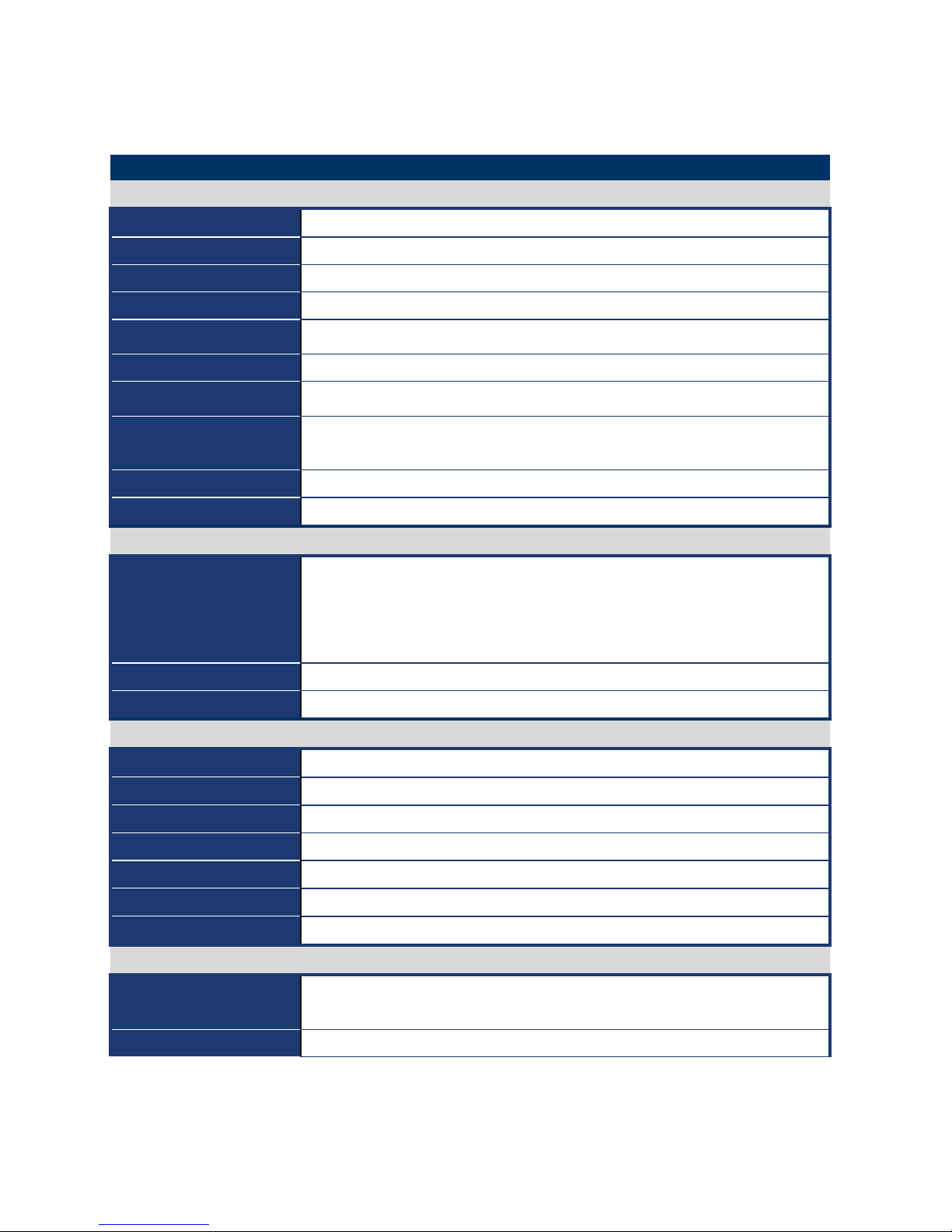
Specifications Summary
Specifications
System
CPU
Intel Core i7/i5/i3 Mobile Processor
BIOS
AMI 32Mb SPI BIOS
System Chipset
Intel QM57/HM55 Chipset
I/O Chipset
Winbond W83667HG-A
Memory
2 x 200-pin SODIMM socket supports up to 8 GB Dual channel DDR3 1066/800
SDRAM
Watchdog Timer
Reset: 1 sec.~255 min. and 1 sec. or 1 min./step
H/W Status Monitor
Monitoring CPU temperature, voltage, and cooling fan status. Auto throttling
control when CPU overheats
Expansion Slots
1x PCI-E x16 (PEG & SDVO)
1x Mini PCI-E x1
S3
S3 Support
SmartFan Control
Yes
I/O
MIO
2 x COM(1F/1R) with power 4 x SATA/SATAII
1 x Display Port 1 x HDMI
1 x VGA 1 x LVDS
1 x LVDS backlight
USB
8 x USB 2.0 ports
DIO
8-bit General Purpose I/O for DI and DO
Display
Chipset
Intel Graphics Media Accelerator HD
Display Memory
Intel DVMT supports 1.7GB video memory
Resolution
2048 x 1536 @ 32 bpp(@ 60Hz)
Dual Display
CRT + LVDS, CRT + Display Port ,CRT + HDMI
LVDS
Dual-channel 24-bit LVDS
Display Port
Support eDP Standard Version 1.1
HDMI
TI Level Shift SN75DP139RGZR
Audio
Audio Codec
Realtek ALC888 Audio Codec
5.1+2 CH. with two independent audio stream
Audio Interface
Mic in, Line in, Line out
Data Modul AG - www.data-modul.com
User’s Manual
IX57QM/IX55HM
9
Ethernet
LAN1
Intel® 82577-LM Gigabit LAN
LAN2
Realtek RTL8111C PCI-E Gigabit LAN
Mechanical & Enviormental
Power Type
ATX
Operating Temperature
0~60°C (32~140°F)
Operating Humidity
0%~90% relative humidity, non-condensing
Size (L x W)
6.69" x 6.69" (170 mm x 170 mm)
Weight 0.88 lbs (0.4 Kg)
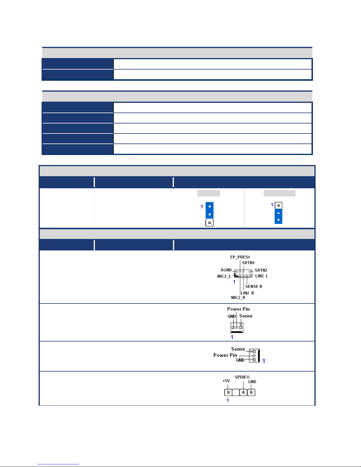
Jumpers
Label Function Note
CLRTC Clear CMOS Normal * Clear CMOS
Connectors
Label Function Note
AAFP1 Front Panel Audio
Connector
CHA_FAN Chassis Fan Connector
CPU_FAN CPU Fan Connector
SPDIF_OUT1 Digital Audio connector
Data Modul AG - www.data-modul.com

IX57QM/IX55HM
10
F_PANEL1 System Panel
Connector
JDIO1 Digital I/O Connector
JBKL1 LCD Inverter Connector
SPI1 SPI Connector
COM2 Serial Port Connector
USB56,
USB78
USB 2.0 Connector
JLVDS1 LVDS Connector
* Specifications are subject to change without notice.
Data Modul AG - www.data-modul.com
User’s Manual
IX57QM/IX55HM
11
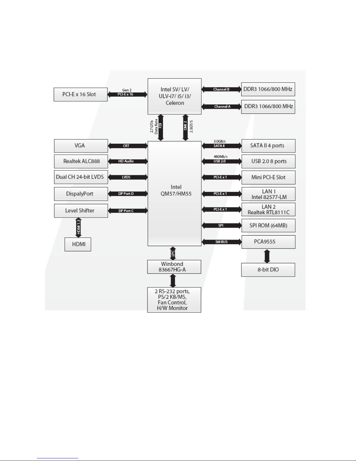
Block Diagram
Data Modul AG - www.data-modul.com

IX57QM/IX55HM
12
This chapter describes the motherboard
features and the new technologies
it supports.
1
Product
introduction
1
Product
introduction
Data Modul AG - www.data-modul.com
 Loading...