

Data Modul EMX-CDT User Manual

User Manual
(0;&'7
,QWHO$WRP
&HGDU7UDLO0LQL,7;0RWKHUERDUG
:LWK,QWHO'3URFHVVRU
10&KLSVHW
1st Ed --XQH 201
Version: January 2013

EMX-CDT User’s Manual
2 EMX-CDT User’s Manual
Content
1. Getting Started ............................................................................................................ 4
1.1 Safety Precautions ..................................................................................................
4
1.2 Packing List ............................................................................................................ 4
1.3 Document Amendment History ....................................................................... 5
1.4 Manual Objectives .......................................................................................... 6
1.5 Specifications ................................................................................................. 7
1.6 Architecture Overview—Block Diagram.......................................................... 9
2. Hardware Configuration ........................................................................................... 10
2.1 Product Overview ......................................................................................... 11
2.1.1 Main board layout .................................................................................. 11
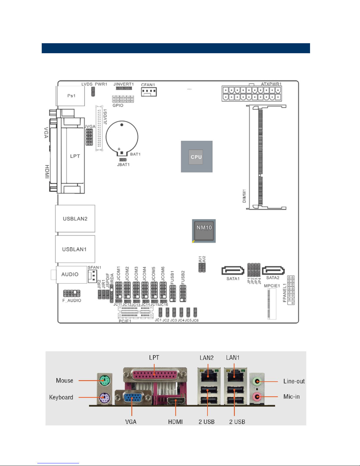
2.1.2 Connecting Rear Panel I/O Devices ...................................................... 11
2.2 Installation Procedure ................................................................................... 12
2.3 Setting Jumpers & Connectors ..................................................................... 13
2.3.1 LVDS _PWR1 ....................................................................................... 13
2.3.2 20PIN ATXPWR .................................................................................... 13
2.3.3 JLVDS1 ................................................................................................. 14
2.3.4 JU1/ JU2 ............................................................................................... 15
2.3.5 JP1-JP4 ................................................................................................. 15
2.3.6 JIR1/ JIR2 ............................................................................................. 16
2.3.7 FPANEL1 .............................................................................................. 16
2.3.8 JVGA ..................................................................................................... 17
2.3.9 GPIO ..................................................................................................... 17
2.3.10 JINVERT1 ............................................................................................. 18
2.3.11 IRDA ...................................................................................................... 18
2.3.12 FUSB1/FUSB2 ...................................................................................... 19
2.3.13 F_AUDIO ............................................................................................... 19
2.3.14 JSPDIF1 ................................................................................................ 20
2.3.15 JCOM1-6 ............................................................................................... 20
2.3.16 JCOM1-6 (9th Pin definition) ................................................................. 21
3.BIOS Setup .................................................................................................................... 22
3.1 Introduction ................................................................................................... 23
3.2 Starting Setup ............................................................................................... 23
3.3 Using Setup .................................................................................................. 24
3.4 Getting Help ................................................................................................. 25
3.5 In Case of Problems ..................................................................................... 25
3.6 BIOS setup ................................................................................................... 26
Data Modul AG - www.data-modul.com

EMX-CDT User’s Manual
EMX-CDT User’s Manual 3
3.6.1 Main Menu ............................................................................................ 26
3.6.1.1 System Language ......................................................................... 26
3.6.1.2 System Date ................................................................................. 26
3.6.1.3 System Time ................................................................................. 26
3.6.2 Advanced BIOS settings ....................................................................... 27
3.6.2.1 ACPI Settings ................................................................................... 27
3.6.2.2 RTC Wake Settings ....................................................................... 28
3.6.2.3 CPU Configuration ........................................................................ 29
3.6.2.4 IDE Configuration .......................................................................... 30
3.6.2.5 USB Configuration ........................................................................ 30
3.6.2.6 Power Management ...................................................................... 31
3.6.2.7 W83627UHG Super IO Configuration ........................................... 32
3.6.2.8 WatchDogTimer Setting ................................................................ 33
3.6.2.9 W83627UHG HW Monitor ............................................................. 34
3.6.3 Chipset ..................................................................................................... 34
3.6.3.1 Host bridge ................................................................................... 35
3.6.3.2 South bridge ................................................................................. 36
3.6.4 Boot settings ......................................................................................... 37
3.6.5 Security ................................................................ ................................ . 38
3.6.5.1 Administrator Password ................................................................ 38
3.6.5.2 User Password.............................................................................. 38
3.6.6 Save & Exit ............................................................................................ 38
3.6.6.1 Save Changes and Exit ................................................................ 39
3.6.6.2 Discard Changes and Exit ............................................................ 39
3.6.6.3 Save Changes and Reset ............................................................. 39
3.6.6.4 Discard Changes and Reset ......................................................... 39
3.6.6.5 Save Changes .............................................................................. 39
3.6.6.6 Discard Changes .......................................................................... 39
3.6.6.7 Restore Defaults ........................................................................... 39
3.6.6.8 Save as user defaults ................................................................... 39
3.6.6.9 Restore as user defaults ............................................................... 40
3.6.6.10 Boot override ................................................................................ 40
4. Drivers Installation....................................................................................................... 41
4.1 Install Audio Driver (For Realtek ALC661 HD Audio) ................................... 42
4.2 Install Chipset Driver (For Intergated Cedar Trail) ........................................ 43
4.3 Install VGA Driver ......................................................................................... 44
4.4 Install LAN Driver (For Realtek 8111E Gigabit Ethernet) ............................. 45
5. Mechanical Drawing .................................................................................................... 46
Data Modul AG - www.data-modul.com
EMX-CDT User’s Manual
4 EMX-CDT User’s Manual
1. Getting Started
1.1 Safety Precautions
Warning!
Always completely disconnect the power cord from your
chassis whenever you work with the hardware. Do not
make connections while the power is on. Sensitive
electronic components can be damaged by sudden power
surges. Only experienced electronics personnel should
open the PC chassis.
Caution!
Always ground yourself to remove any static charge before
touching the CPU card. Modern electronic devices are very
sensitive to static electric charges. As a safety precaution,
use a grounding wrist strap at all times. Place all electronic
components in a static-dissipative surface or static-shielded
bag when they are not in the chassis.
Always note that improper disassembling action could cause damage to the
motherboard. We suggest not removing the heatsink without correct
instructions in any circumstance. If you really have to do this, please contact
us for further support.
1.2 Packing List
Before you begin installing your single board, please make sure that the
following materials have been shipped:
Rear I/O bracket X 1
Quick Installation Guide X 1
Driver/Utility CD X 1
Serial ATA Signal Cable X 1
COM Cable X 1
Motherboard X 1
Data Modul AG - www.data-modul.com

EMX-CDT User’s Manual
EMX-CDT User’s Manual 5
1.3 Document Amendment History
Revision
Date
By
Comment
1st
June 2012
Avalue
Initial Release
Data Modul AG - www.data-modul.com

EMX-CDT User’s Manual
6 EMX-CDT User’s Manual
1.4 Manual Objectives
This manual describes in details
Avalue Technology EMX-CDT Single Board.
We have tried to include as much information as possible but we have not duplicated
information that is provided in the standard IBM Technical References, unless it proved to
be necessary to aid in the understanding of this board.
We strongly recommend that you study this manual carefully before attempting to set up
EMX-CDT series or change the standard configurations. Whilst all the necessary
information is available in this manual we would recommend that unless you are confident,
you contact your supplier for guidance.
Please be aware that it is possible to create configurations within the CMOS RAM that
make booting impossible. If this should happen, clear the CMOS settings, (see the
description of the Jumper Settings for details).
If you have any suggestions or find any errors regarding this manual and want to inform us
of these, please contact our Customer Service department with the relevant details.
Data Modul AG - www.data-modul.com
EMX-CDT User’s Manual
EMX-CDT User’s Manual 7
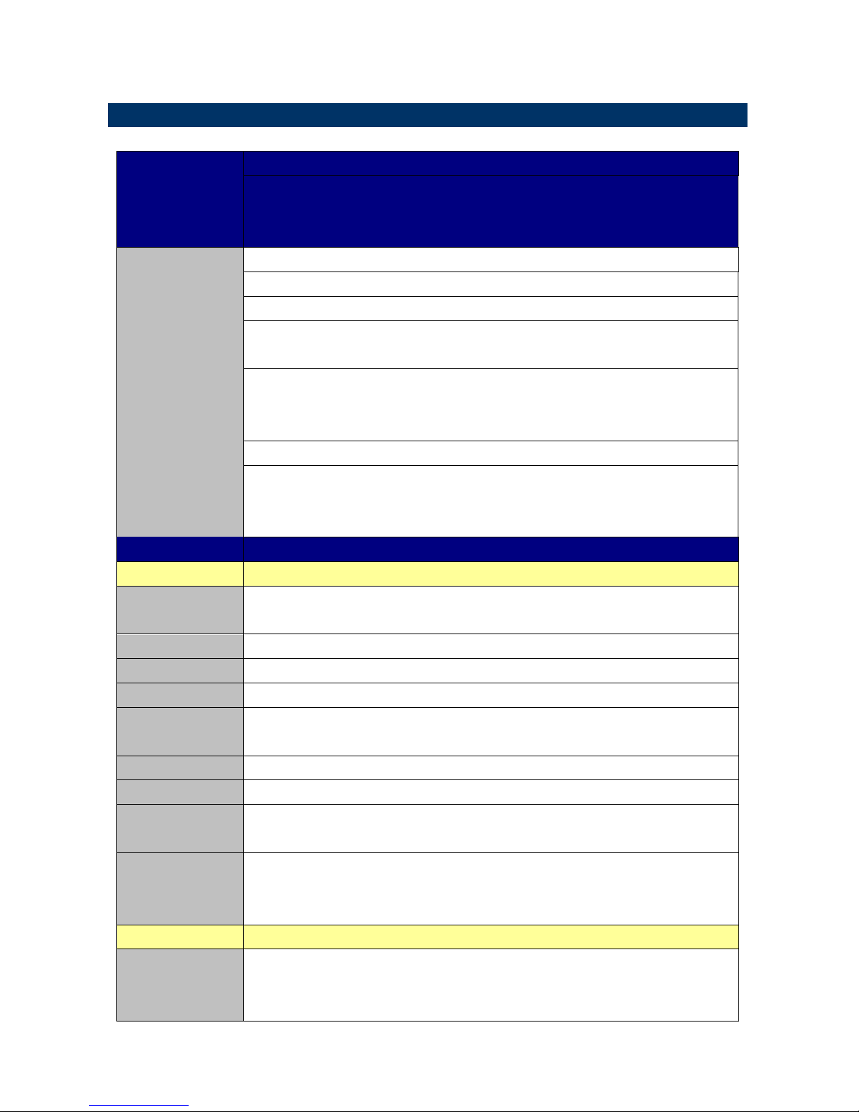
1.5 Specifications
Title
EMX-CDT
Intel® Atom™ Cedar Trail Mini ITX Motherboard
With Intel® D2550 Processor + NM10 Chipset
Features
Mini-ITX
Onboard Intel® Atom™ processor Cedar Trail
IOH: NM10
One 204-pin DDR3 1066/1033MHZ SO-DIMM socket, supports up to 4GB
Max
1x VGA
1x HDMI
1x 18/24 bit single-channel LVDS
2x Realtek RT8111E PCIe Gigabit Ethernet
1x Mini PCI-e socket
*Mini PCI-e and M-SATA SSD switch through Jumper
1x PCIE x1
Specifications
System
CPU
Onboard Intel® Atom™ Processor D2550 Cedar Trail (1M Cache, 1.86
GHz)
BIOS
AMI 16MBit SPI BIOS
System Chipset
Intel® NM10
I/O Chip
Winbond W83627UHG
System Memory
One 204-pin DDR3 1066/1333MHZ SO-DIMM socket, supports up to 4GB
Max
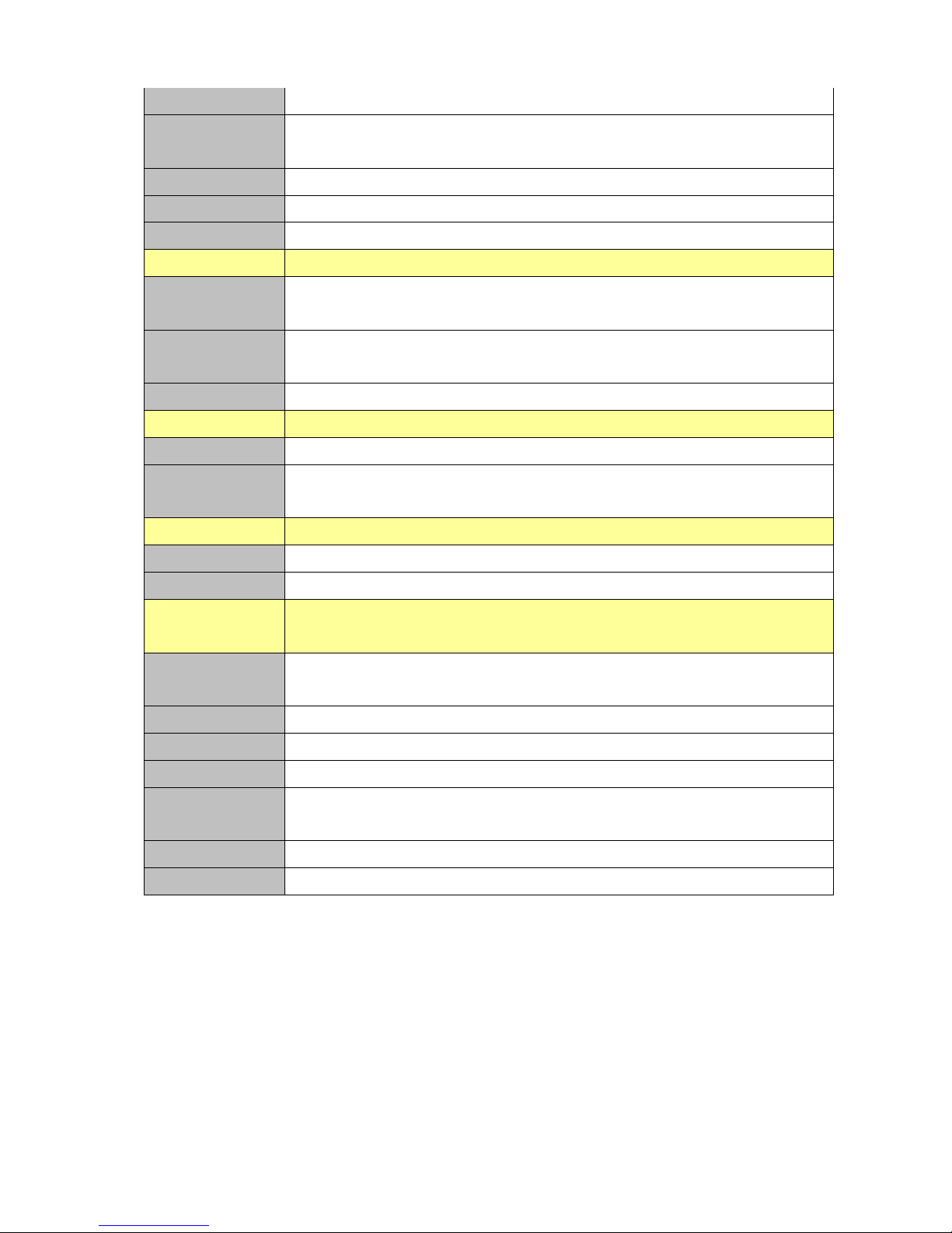
SSD
NA
Watchdog Timer
Reset : 1 to 255 sec/min per step
H/W Status
Monitor
Monitoring temperature, voltage, and cooling fan
status. Auto throttling control when CPU overheats
Expansion
1x Mini PCI-e socket
*Mini PCI-e and m-SATA SSD switch through Jumper
1x PCIE x1
I/O
MIO
Serial port x 6 internal RS-232 ports with 5V/12V power
2x SATAII Connector(3Gb/s)
1 x 10 pin-headers for VGA output port (The I/O VGA DB15 connector &
Data Modul AG - www.data-modul.com
EMX-CDT User’s Manual
8 EMX-CDT User’s Manual
1 x 10 pin-headers can’t use in the same time)
USB
8 x USB 2.0/1.1
4 x internal USB port (pin-header) ,4x rear I/O connectors
Parallel Port
1 x LPT port rear I/O connectors
PS2 KB/MS
1 x PS2 keyboard , 1 x PS2 Mouse
DIO
supports 8-bit General Purpose I/O for DI and DO
Display
Chipset
Integrated Intel® Graphics Media Accelerator 3650
(Gfx freq @ 640Mhz) support DX9
Resolution
VGA /HDMI Display: 1920 x 1200
Internal LVDS 1440 x 900
Dual Display
Yes , LVDS+VGA, VGA+HDMI, HDMI+LVDS
Audio
Audio Codec
Realtek ALC661 HD Audio Decoding controller
Audio Interface
Mic-in ,Line out
Support On-board S/PDIF input/output
Ethernet
LAN Chip
2 x Realtek RT8111E PCIe Gigabit Ethernet
Ethernet Interface
10 /100 /1000 Base-Tx Gigabit Ethernet
Mechanical &
Environmental
Power
Requirement
+12V/+5V/5Vsb/+3.3V
Power Type
ATX
Operating Temp.
0 ~ 60°C (32 ~ 140°F)
Storge Temp
-40 ~ 75°C (-40 ~ 167°F)
Operating
Humidity
0 ~ 90% Relative Humidity, Non-condensing
Size (L x W)
6.69” x 6.6” (170mm x 170mm)
Weight
1.058lbs (0.48kg)
Data Modul AG - www.data-modul.com
EMX-CDT User’s Manual
EMX-CDT User’s Manual 9
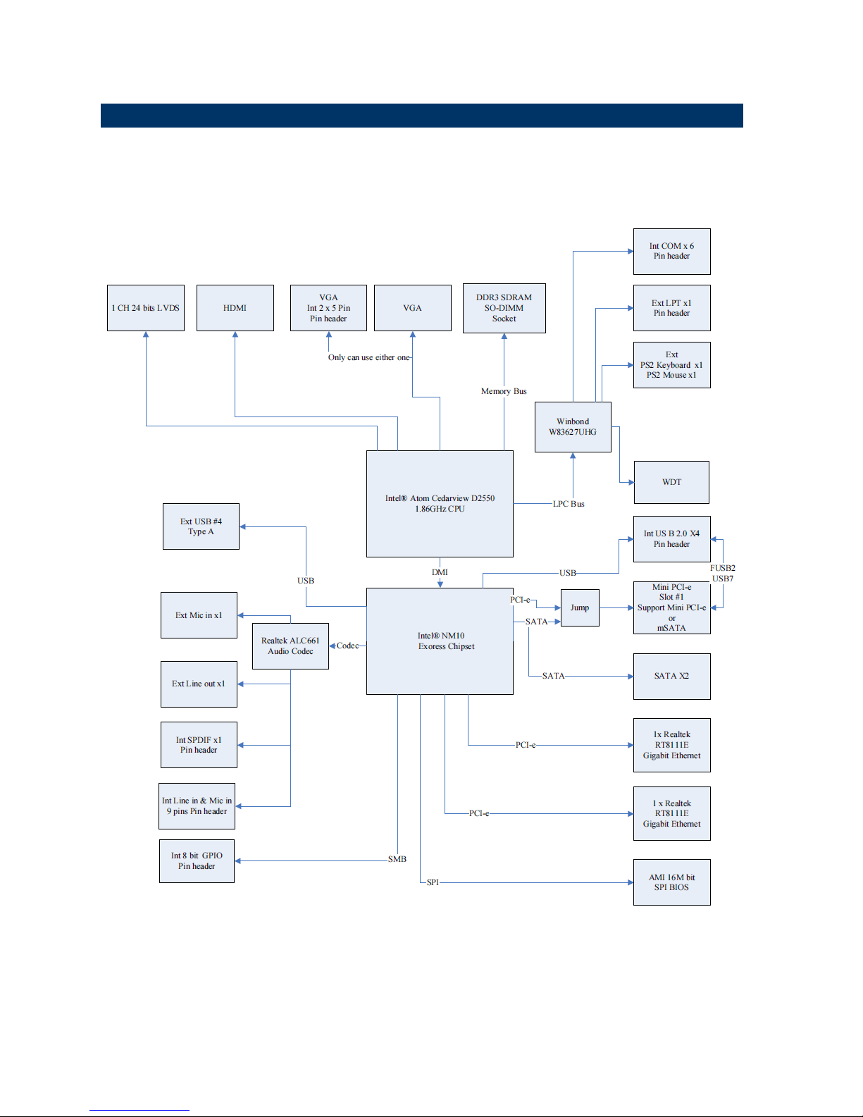
1.6 Architecture Overview—
Block Diagram
The following block diagram shows the architecture and main components of EMX-CDT.
Data Modul AG - www.data-modul.com

EMX-CDT User’s Manual
10 EMX-CDT User’s Manual
2. Hardware
Configuration
Data Modul AG - www.data-modul.com
EMX-CDT User’s Manual
EMX-CDT User’s Manual 11
2.1 Product Overview
2.1.1 Main board layout
2.1.2 Connecting Rear Panel I/O Devices
Data Modul AG - www.data-modul.com

EMX-CDT User’s Manual
12 EMX-CDT User’s Manual
2.2 Installation Procedure
This chapter explains you the instructions of how to setup your system.
1. Turn off the power supply.
2. Insert the DIMM module (be careful with the orientation).
3. Insert all external cables for hard disk, floppy, keyboard, mouse, USB etc. except for flat
panel. A CRT monitor must be connected in order to change CMOS settings to support
flat panel.
4. Connect power supply to the board via the ATXPWR.
5. Turn on the power.
6. Enter the BIOS setup by pressing the delete key during boot up. Use the "Save & Exit \
Restore Defaults" feature.
7. If TFT panel display is to be utilized, make sure the panel voltage is correctly set before
connecting the display cable and turning on the power.
Data Modul AG - www.data-modul.com
EMX-CDT User’s Manual
EMX-CDT User’s Manual 13
2.3 Setting Jumpers & Connectors
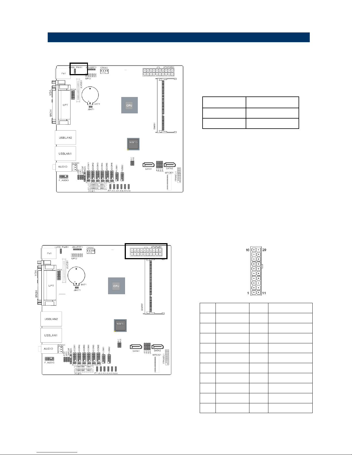
2.3.1 LVDS _PWR1
Pin No.
Definition
1-2
5V
2-3
3.3V
1-2, Set JLVDS1 Pin1,2,5,6 VDDSAFE as 5V
2-3, Set JLVDS1 Pin1,2,5,6 VDDSAFE as 3.3V
2.3.2 20PIN ATXPWR
Pin No.
Definition
Pin No.
Definition
1
+3.3V 2 +3.3V
3
GND 4 +5V
5
GND 6 +5V
7
GND 8 PWR OK
9
+5VSB
10
+12V
11
+3.3V
12
-12V
13
GND
14
PS-ON
15
GND
16
GND
17
GND
18
-5V
19
+5V
20
+5V
Data Modul AG - www.data-modul.com
EMX-CDT User’s Manual
14 EMX-CDT User’s Manual
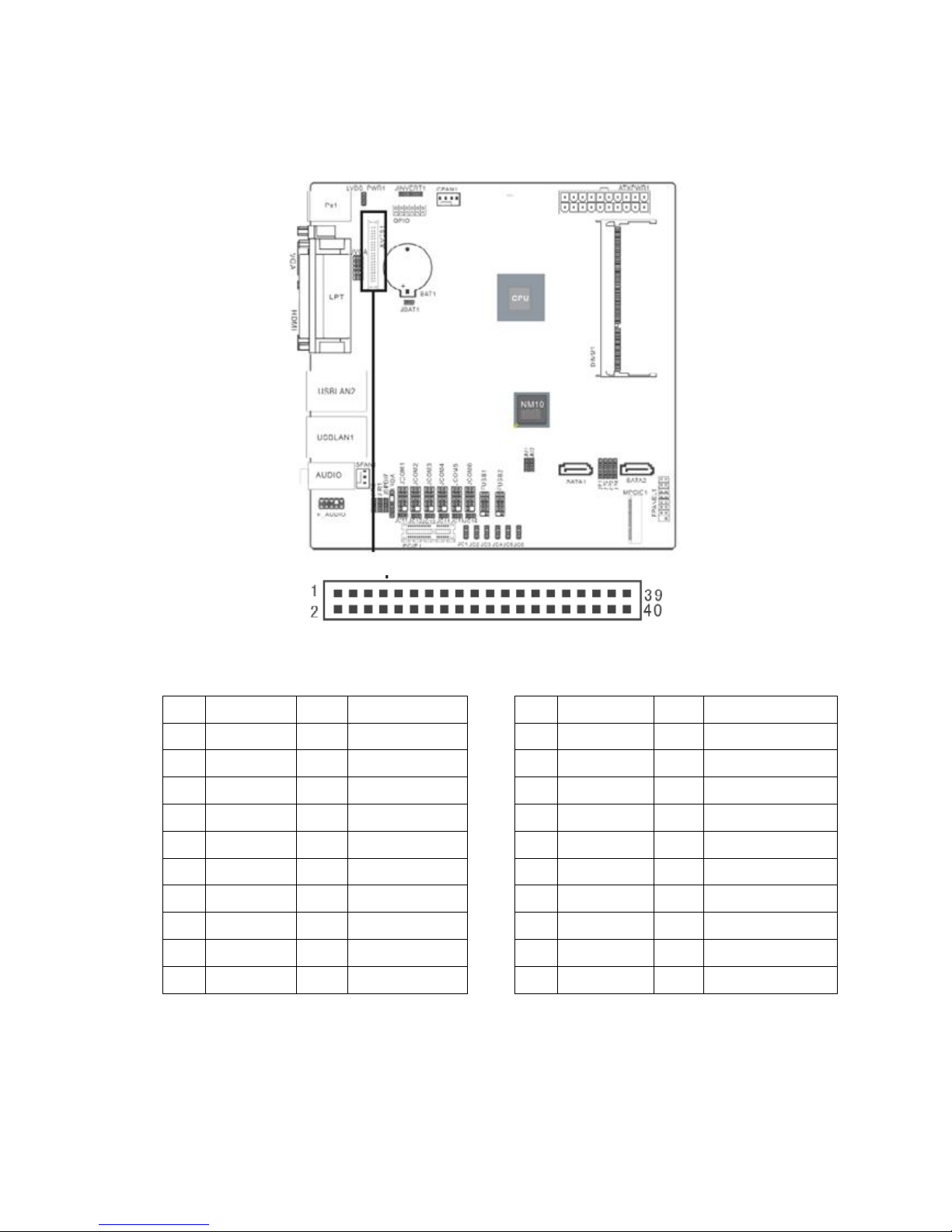
2.3.3 JLVDS1
Pin No.
Definition
Pin No.
Definition
1
VDDSAFE
2
VDDSAFE
3
GND 4 GND
5
VDDSAFE
6
VDDSAFE
7
LVDS0_N0 8 NC
9
LVDS0_P0
10
NC
11
GND
12
GND
13
LVDS0_N1
14
NC
15
LVDS0_P1
16
NC
17
GND
18
GND
19
LVDS0_N2
20
NC
Pin No.
Definition
Pin No.
Definition
21
LVDS0_P2
22
NC
23
GND
24
GND
25
LVDS0_CLKN
26
NC
27
LVDS0_CLKP
28
NC
29
GND
30
GND
31
LVDS_DDCPCLK
32
LVDS_DDCPDATA
33
GND
34
GND
35
LVDS0_N3
36
NC
37
LVDS0_P3
38
NC
39
NC
40
LVDS_VCON
Data Modul AG - www.data-modul.com
EMX-CDT User’s Manual
EMX-CDT User’s Manual 15
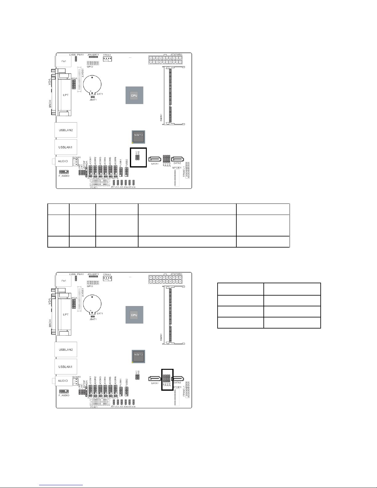
2.3.4 JU1/ JU2
Pin No.
Definition
FUSB2 (USB7)
Mini PCI-e WiFi Card (USB interface)
Mini PCI-e Card
1-2
FUSB2
Enabled
Don’t use USB interface Mini PCI-e card
in the Mini PCI-e slot
Enabled
2-3
MINIPCIE
Disabled
Enabled
Enabled
2.3.5 JP1-JP4
Pin No.
Definition
1-2
MINIPCIE
2-3
M-SATA
3-4
SATA2
When you want to use Wifi on MINIPCIE1 slot,
please set up JP1-JP4 as 1-2.
When you want to use M-SATA on MINIPCIE1
slot, please set up JP1-JP4 as 2-3.
When you use SATA2 connect, please set up
JP1-JP4 as 3-4.
Data Modul AG - www.data-modul.com
 Loading...