

Data Modul AIMB-258 User Manual

Data Modul AG - www.data-modul.com
User Manual
AIMB-258
Intel® GM45 µFC-PGA 478
Core™2 Duo Mini ITX Motherboard
with VGA, DVI, LVDS, 6 COM, Dual GbE, 8 USB, 2 SATA II, PCIe x 16
Version June 2009

AIMB-258 User Manual ii
Safety Information
Electrical safety
! To prevent electrical shock hazard, disconnect the power cable from the electri-
cal outlet before relocating the system.
! When adding or removing devices to or from the system, ensure that the power
cables for the devices are unplugged before the signal cables are connected. If
possible, disconnect all power cables from the existing system before you add a
device.
! Before connecting or removing signal cables from the motherboard, ensure that
all power cables are unplugged.
! Seek professional assistance before using an adapter or extension cord. These
devices could interrupt the grounding circuit.
! Make sure that your power supply is set to the correct voltage in your area. If
you are not sure about the voltage of the electrical outlet you are using, contact
your local power company.
! If the power supply is broken, do not try to fix it by yourself. Contact a qualified
service technician or your retailer.
Operation safety
! Before installing the motherboard and adding devices on it, carefully read all the
manuals that came with the package.
! Before using the product, make sure all cables are correctly connected and the
power cables are not damaged. If you detect any damage, contact your dealer
immediately.
! To avoid short circuits, keep paper clips, screws, and staples away from connec-
tors, slots, sockets and circuitry.
! Avoid dust, humidity, and temperature extremes. Do not place the product in
any area where it may become wet.
! Place the product on a stable surface.
! If you encounter technical problems with the product, contact a qualified service
technician or your retailer.
Part No. 2006025801 Edition 2
Printed in Taiwan
June 2009
Caution! The symbol of the crossed out wheeled bin indicates that the product
(electrical and electronic equipment) should not be placed in municipal
waste. Check local regulations for disposal of electronic products.
iii AIMB-258 User Manual
Certifications
This device complies with the requirements in part 15 of the FCC rules: Operation is
subject to the following two conditions:
! This device may not cause harmful interference,
! This device must accept any interference received, including interference that
may cause undesired operation.
This equipment has been tested and found to comply with the limits for a Class A digital device, pursuant to Part 15 of the FCC Rules. These limits are designed to provide reasonable protection against harmful interference when the equipment is
operated in a commercial environment. This equipment generates, uses, and can
radiate radio frequency energy and, if not installed and used in accordance with the
instruction manual, may cause harmful interference to radio communications. Operation of this device in a residential area is likely to cause harmful interference in which
case the user will be required to correct the interference at his/her own expense. The
user is advised that any equipment changes or modifications not expressly approved
by the party responsible for compliance would void the compliance to FCC regulations and therefore, the user's authority to operate the equipment.
Caution! There is a danger of a new battery exploding if it is incorrectly installed.
Do not attempt to recharge, force open, or heat the battery. Replace the
battery only with the same or equivalent type recommended by the manufacturer. Discard used batteries according to the manufacturer's
instructions.

AIMB-258 User Manual iv
Technical Support
If a problem arises with your system and no solution can be obtained from the user’s
manual, please contact your place of purchase or local distributor. Alternatively,
please try the following help resources for further guidance. Visit the Advantech website for FAQ, technical guide, BIOS updates, driver updates, and other information:
http://support.advantech.com.tw/Support/default.aspx
Packing List
Before you begin installing your single board, please make sure that the following
materials have been shipped:
! 1 x AIMB-258 Intel® µFC-PGA 478 Core 2 Duo Mini ITX Motherboard
! 2 x SATA HDD cable
! 2 x SATA Power cable
! 1 x Serial port cable 1 to 4
! 1 x I/O port bracket
! 1 x Startup manual
! 1 x Driver CD
! 1 x Warranty card
If any of the above items is damaged or missing, please contact your retailer.

v AIMB-258 User Manual
Contents
Chapter 1 Product Introduction ...........................1
1.1 Before You Proceed.................................................................................. 2
1.2 Motherboard Overview.............................................................................. 2
1.2.1 Placement Direction...................................................................... 2
1.2.2 Screw Holes.................................................................................. 3
1.3 Motherboard Layout .................................................................................. 4
Figure 1.1 Motherboard Layout ................................................... 4
1.4 Specifications ............................................................................................ 5
1.5 Operating System support list ................................................................... 6
1.6 Board Diagram .......................................................................................... 7
1.7 Ordering Information ................................................................................. 8
1.8 Riser Card ................................................................................................. 8
1.9 Bracket View ............................................................................................. 8
1.10 Accessories............................................................................................... 8
1.11 Layout Content List ................................................................................... 9
Table 1.1: Jumper Setting List ..................................................... 9
Table 1.2: JSETCOM1: COM1/+5 V/+12 V Selection ................. 9
Table 1.3: JSETCOM2: COM2 RS232/422/485 Mode Selection 9
Table 1.4: CMOS1: Clear CMOS .............................................. 10
Table 1.5: J1:LCD Power 3.3 V/5.5 V Selection........................ 10
Table 1.6: PSON1: ATX, AT Mode Selection............................ 10
Table 1.7: JWDT1: Watchdog Timer Output Option.................. 11
Table 1.8: JOBS: HW monitor ................................................... 11
1.12 Central Processing Unit (CPU) for AIMB-258 ......................................... 11
1.12.1 Installing the CPU ....................................................................... 12
1.12.2 Installing the CPU Heatsink and Fan .......................................... 14
1.12.3 Uninstalling the CPU Heatsink and Fan...................................... 16
1.13 System Memory ...................................................................................... 17
1.13.1 DIMM Sockets Location .............................................................. 17
1.13.2 System Memory .......................................................................... 17
1.13.3 Memory Support List................................................................... 18
Table 1.9: SODIMM DDR3 ........................................................ 18
1.14 Connectors.............................................................................................. 19
1.14.1 Rear Panel Connectors............................................................... 19
Table 1.10:Rear Panel Connectors ............................................ 19
Table 1.11:LEDs......................................................................... 19
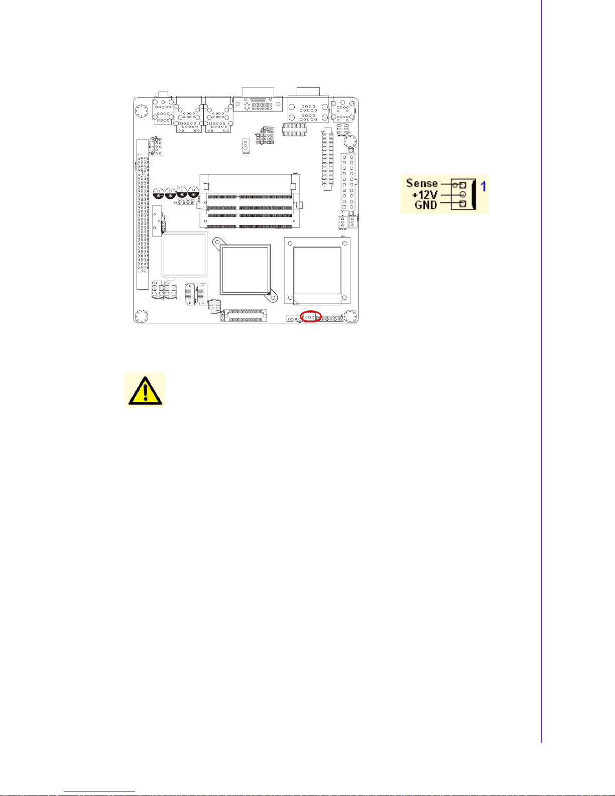
1.14.2 CPU Fan Connector (CPUFAN1) ............................................... 20
1.14.3 System Fan Connector (SYSFAN1, SYSFAN2) ......................... 21
1.14.4 Serial Port Connector 3456 (COM3456)..................................... 22
1.14.5 Front Headphone Connector (HD1)............................................ 22
1.14.6 Front Panel Connector (JFP1/JFP2/JFP3) ................................. 23
1.14.7 ATX soft power switch (JFP1 / PWR_SW) ................................. 23
1.14.8 Reset (JFP1 / RESET)................................................................ 23
1.14.9 HDD LED (JFP2 / HDDLED)....................................................... 23
1.14.10External speaker (JFP2 / SPEAKER) ......................................... 23
1.14.11Power LED and keyboard lock connector
(JFP3 / PWR_LED&KEY LOCK) ................................................ 24
Table 1.12:ATX power supply LED status
(No support for AT power)........................................ 24
1.14.12USB 2.0 Connector (USB56, USB78)......................................... 24
1.14.13ATX Power Connector (ATX1).................................................... 25
1.14.14LCD Inverter Connector (VP1).................................................... 26
1.14.15LVDS Connector (LVDS1) .......................................................... 26
1.14.16Digital I/O Connector (DIO_CN1)................................................ 27

AIMB-258 User Manual vi
1.14.17Serial ATA Connector 1 & 2 (SATA1, SATA2) ........................... 27
1.14.18PCIe x 16 Slot (PCIE X 16)......................................................... 28
1.14.19SPI Flash Connector(SPI_CN1) ................................................. 28
1.14.20Memory Connector Channel A/B(DIMM1/2)............................... 29
1.14.21SPDIF1 out connector(SPDIF1) ................................................. 29
1.14.22CF connector .............................................................................. 30
Chapter 2 BIOS Operation ................................. 31
2.1 BIOS Introduction.................................................................................... 32
2.2 BIOS Setup ............................................................................................. 32
2.2.1 Main Menu.................................................................................. 33
2.2.2 Standard CMOS Features .......................................................... 34
2.2.3 Advanced BIOS Features........................................................... 35
2.2.4 Advanced Chipset Features ....................................................... 36
2.2.5 Integrated Peripherals ................................................................ 37
2.2.6 USE Device Setting .................................................................... 39
2.2.7 Power Management Setup ......................................................... 40
2.2.8 PnP/PCI Configurations.............................................................. 42
2.2.9 PC Health Status ........................................................................ 42
2.2.10 Load Setup Defaults ................................................................... 43
2.2.11 Set Password.............................................................................. 43
Chapter 3 Chipset Software Install Utility ........ 45
3.1 Before you Begin .................................................................................... 46
3.2 Introduction ............................................................................................. 46
3.3 Windows Vista/XP Driver Setup.............................................................. 47
Chapter 4 VGA Setup ......................................... 49
4.1 Introduction ............................................................................................. 50
4.2 Windows Vista/XP Driver Setup.............................................................. 50
Chapter 5 LAN Configuration ............................ 51
5.1 Introduction ............................................................................................. 52
5.2 Features.................................................................................................. 52
5.3 Installation............................................................................................... 52
5.4 Windows Vista/XP Driver Setup (Realtek RTL8111C)............................ 52
Appendix A Programming the Watchdog Timer .55
A.1 Programming the Watchdog Timer ......................................................... 56
A.1.1 Watchdog timer overview ........................................................... 56
A.1.2 Programming the Watchdog Timer............................................. 56
Table A.1: Watchdog Timer Registers....................................... 58
A.1.3 Example Program ....................................................................... 59
Appendix B Pin Assignments............................... 63
B.1 USB Connector (USB56,USB78)............................................................ 64
Table B.1: USB5/USB6 Connector (USB56) ............................. 64
B.2 VGA Connector (VGA1A) ....................................................................... 64
Table B.2: VGA Connector (VGA1A)......................................... 64

vii AIMB-258 User Manual
B.3 DVI Connector (VGA1B) ......................................................................... 64
Table B.3: DVI Connector (VGA1B)........................................... 64
B.4 RS-232 Serial Port (COM1~COM2)........................................................ 65
Table B.4: RS-232 Serial Port (COM1~COM2) ......................... 65
B.5 RS-232 Serial Port (COM3 ~ COM6)...................................................... 66
Table B.5: RS-232 Serial Port (COM23).................................... 66
B.6 PS/2 Keyboard/ Mouse Connector (KBMS1) .......................................... 67
Table B.6: PS/2 Keyboard/ Mouse Connector (KBMS1) ...........67
B.7 CPU Fan Power Connector (CPUFAN1) ................................................ 67
Table B.7: CPU Fan Power Connector (CPUFAN1).................. 67
B.8 Power LED & Keyboard Lock Connector (JFP3) .................................... 68
Table B.8: Power LED and Keylock Connector (JFP3) ............ 68
B.9 HDD LED and External Speaker Connector
(JFP2/HDD LED and SPEAKER)............................................................ 68
Table B.9: External Speaker Connector (JFP2/SPEAKER)....... 68
B.10 ATX Soft Power Switch and Reset Connector
(JFP1/ PWR-SW and RESET) ................................................................ 69
Table B.10:Audio Front Panel Connector (JFP1/ RESET) ......... 69
B.11 Audio Front Panel Connector (FPAUD1) ................................................ 69
Table B.11:Audio front panel connector (FPAUD1) .................... 69
B.12 GPIO Pin Header (GPIO1)...................................................................... 70
Table B.12:GPIO Pin Header (GPIO1) ....................................... 70
B.13 LVDS Connector (LVDS1) ...................................................................... 71
Table B.13:LVDS Connector (LVDS1)........................................ 71
B.14 LVDS Power Jumper (J1) ....................................................................... 72
Table B.14:LVDS Power Jumper (J1)......................................... 72
B.15 LVDS Invert (VP1)................................................................................... 72
Table B.15:LVDS Invert (VP1) .................................................... 72
B.16 System I/O Ports ..................................................................................... 73
Table B.16:System I/O Ports ...................................................... 73
B.17 DMA Channel Assignments .................................................................... 73
Table B.17:DMA Channel Assignments...................................... 73
B.18 Interrupt Assignments ............................................................................. 74
Table B.18:Interrupt Assignments............................................... 74
B.19 1st MB Memory Map ............................................................................... 74
Table B.19:1st MB Memory Map ................................................ 74

AIMB-258 User Manual viii

Chapter 1
1 Product Introduction
This chapter describes the main
board features and the new technologies it supports.

AIMB-258 User Manual 2
1.1 Before You Proceed
Take note of the following precautions before you install motherboard components or
change any motherboard settings.
1.2 Motherboard Overview
Before you install the motherboard, study the configuration of your chassis to ensure
that the motherboard fits into it. Refer to the chassis documentation before installing
the motherboard.
1.2.1 Placement Direction
When installing the motherboard, make sure that you place it into the chassis in the
correct orientation. The edge with external ports goes to the rear part of the chassis.
Caution!
!
Unplug the power cord from the wall socket before touching any
component.
!
Use a grounded wrist strap or touch a safely grounded object or a
metal object, such as the power supply case, before handling components to avoid damaging them due to static electricity
!
Hold components by the edges to avoid touching the ICs on them.
!
Whenever you uninstall any component, place it on a grounded
antistatic pad or in the bag that came with the component.
!
Before you install or remove any component, ensure that the ATX
power supply is switched off or the power cord is detached from the
power supply. Failure to do so may cause severe damage to the
motherboard, peripherals, and/or components.
Warning! Make sure to unplug the power cord before installing or removing the
motherboard. Failure to do so can cause you physical injury and damage motherboard components.
3 AIMB-258 User Manual
Chapter 1 Product Introduction
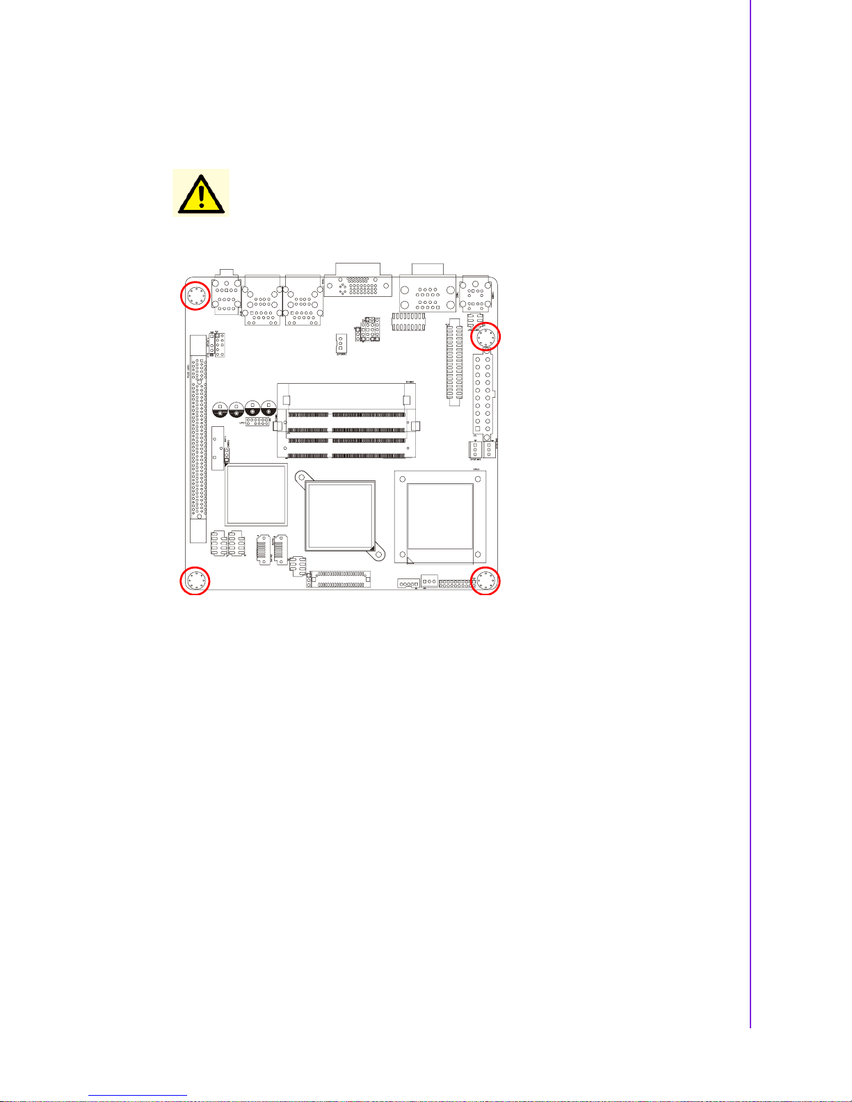
1.2.2 Screw Holes
Place four (4) screws into the holes indicated by circles to secure the motherboard to
the chassis.
Caution! Do not over tighten the screws! Doing so can damage the motherboard.
Place this side towards the rear
of the chassis.
AIMB-258 User Manual 4
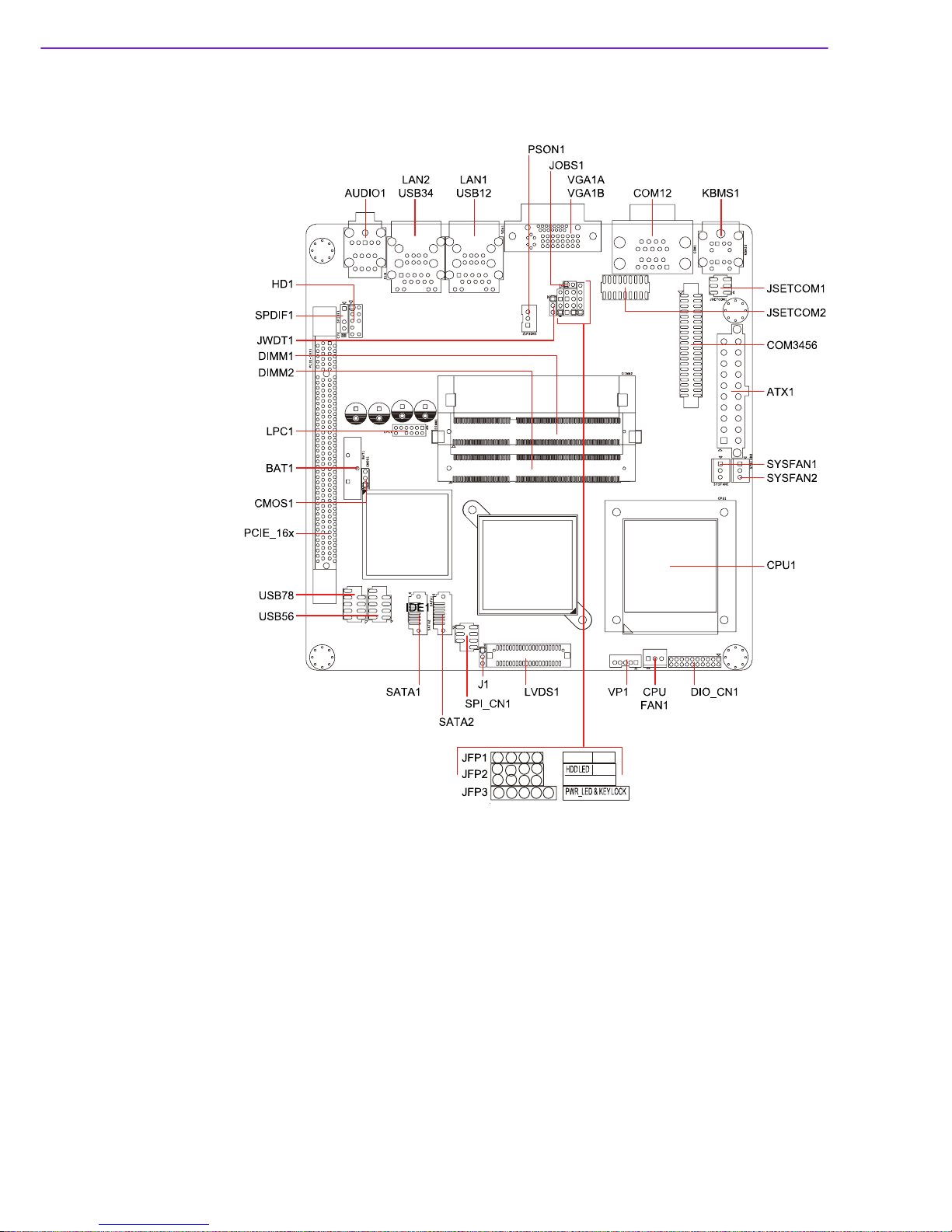
1.3 Motherboard Layout
Figure 1.1 Motherboard Layout
PWR-SW RESET
SPEAKER
1234
2468
13
57
12 345

5 AIMB-258 User Manual
Chapter 1 Product Introduction
1.4 Specifications
Processor System
CPU (45 nm
µFC-PGA 478)
Intel® Core™2 Duo Intel Celeron M
Max. Speed T9400 2.53 GHz 575 2.0 GHz
Front Side Bus 667/800/1066 MHz 667 MHz
L2 Cache 6 MB 1 MB
Chipset GM45 + ICH9M
BIOS Award 16 Mbit, SPI
Expansion Slot
PCI Mini-PCI PCIe x 16 4 GB/s per direction, 1 slot
Memory
Technology DDR3 800/1066 MHz SDRAM
Max. Capacity 4 GB
Socket 2 x 204-pin SODIMM
Graphics
Controller Intel GM45 GMCH integrated Graphics Media Accelerator X4500
VRAM Shared system memory up to 384 MB video memory
LVDS Single channel 18/24-bit/Dual channel 36/48-bit LVDS
DVI-D Yes (if DVI is used, PCIe x16 is automatically disable)
Dual Display VGA + DVI; VGA + LVDS; DVI + LVDS
*Dual Display
Mode
Extended Mode, Clone Mode, Twin Mode
Ethernet
Interface 10/100/1000Base-T
Controller GbE LAN1: Realtek RTL8111C; GbE LAN2: Realtek RTL8111C
Connector RJ-45 x 2
SATA
Max Data Transfer Rate
300 MB/s
Channel 2
SSD Compact Flash Compact Flash Supports compact flash type I/II
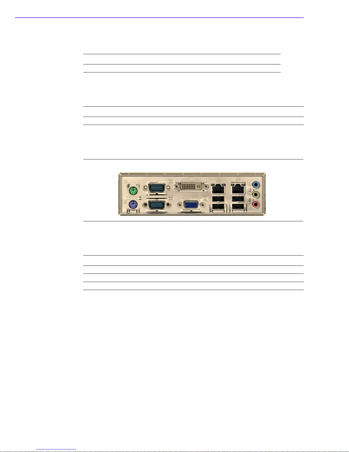
Rear I/O
VGA 1
DVI 1
Ethernet 2
USB 4 (USB 2.0 compliant)
Serial 2 (1 of RS-232, 1 of RS-232/422/485)
PS/2 2 (1 x keyboard and 1 x mouse)
Internal
Connector
LVD S 1
USB 4 (USB 2.0 compliant)
Serial 4 (RS-232)
IDE SATA 2
Audio 3 (Mic-in, Line-in, Line-out)
Compact Flash 1
Parallel IrDA FDD DIO 16-bit General Purpose I/O for digital signal input/output
Watchdog
Timer
Output Interrupt, system reset
Interval Programmable 1 ~ 255 sec/ min

AIMB-258 User Manual 6
*Dual Display Clone uses both display pipes to drive the same content at the same
resolution and color depth to two different displays. This configuration allows for different refresh rates on each display.
Dual Display Twin uses one of the display pipes to drive the same content, at the
same resolution, color depth, and refresh rates to two different displays.
Extended Desktop uses both display pipes to drive different content, at potentially
different resolutions, refresh rates, and color depths, to two different displays. This
configuration allows for a larger Windows desktop by using both displays as one
work surface.
1.5 Operating System support list
Power
Requirement
Power On 5 V 3.3 V 12 V 5 Vsb -12 V
0 . 9 9 A 2 . 6 7 A 2 . 0 7 A 0 . 1 7 A 0 . 0 8 A
Environment
Operating Non-Operating
Temperature 0 ~ 60°C (32 ~ 140°F) -20 ~ 70°C (-4 ~ 158°F)
Physical
Characteristics
Dimensions 170 mm x 170 mm (6.69’ x 6.69’)
Operation System AIMB-258
Windows Vista Ultimate edition
(32-bit/64-bit)
Support
Windows XP professional edition
(32-bit/64-bit)
Support
XP embedded Support
Linux (Fedora) Only OS installation and limited I/O functionality are
validated
QNX Only OS installation and limited I/O functionality are
validated
WinCE 6.0 Require OEM BIOS. Please contact with Advantech
FAE
7 AIMB-258 User Manual
Chapter 1 Product Introduction
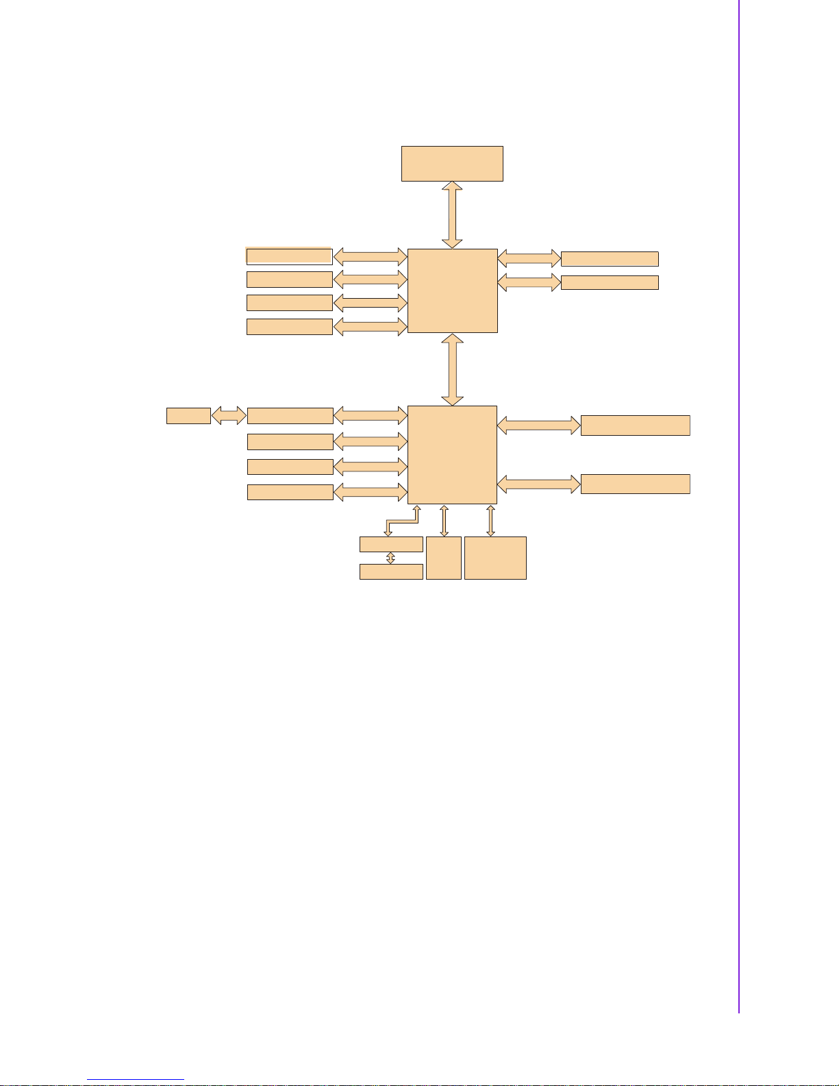
1.6 Board Diagram
Intel GM45n
GMCH
CRT
BIOS
NXP 9555
16-bit GPI O
Super IO
Winbond
W83627UHG
Direc t Medi a Inter face
2GB/s bandwidth
ICH9M
1
0
6
6
/
8
0
0
/
6
6
7
M
H
z
F
S
B
VGA
PCI3 x 16
DDR3 800/1066
Channel A
LVD S
Dual Channel
24-bit LV DS
GbE-LAN 1:R ealtek 8111C
SPI
DVI
PCI3 x 16 slo t
LPC
SM Bus
JMB368
2SATAports
8USBPorts
Realtek ALC888
300MB/s
PCIe x 1
CF
IDE
PCIe x 1
PCIe x 1
U
S
B
2
.
0
/
1
.
1
HD Audio
Intel Socket 478
Core 2 D uo Processor
DDR3 800/1066
ChannelA
GbE-LAN2:Realtek 8111C
AIMB-258 User Manual 8
1.7 Ordering Information
1.8 Riser Card
1.9 Bracket View
1.10 Accessories
Part Number Display GbE SATA Serial CF
AIMB-258G2-00A1E VGA/ DVI/ LVDS Dual 2 6 1
Part Number Description
AIMB-R430P-03A1E 2U riser card with 3 PCI slot expansion
Part Number Description
1700003195 USB cable with four ports, 17.5 cm
1700002204 USB cable with four ports, 27 cm
1700002314 USB cable with four ports, 30.5 cm
9 AIMB-258 User Manual
Chapter 1 Product Introduction
1.11 Layout Content List
Table 1.1: Jumper Setting List
Label Function
JSETCOM1 COM1/+5 V/+12 V Selection
JSETCOM2 COM2 RS232/422/485 Mode Selection
CMOS1 Clear CMOS
J1 LCD Power 3.3 V/5.5 V Selection
PSON1 ATX, AT Mode Selection
JWDT1 Watchdog Timer Output Option
JOBS1 Hardware Monitor
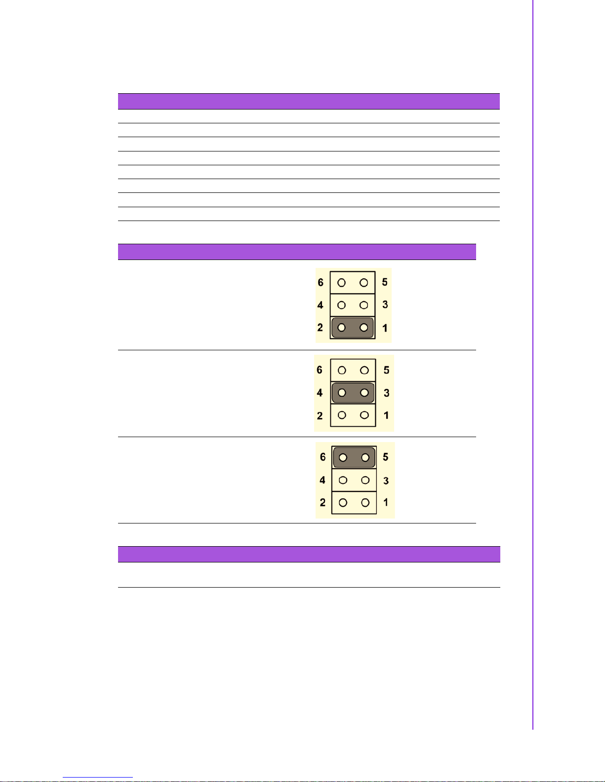
Table 1.2: JSETCOM1: COM1/+5 V/+12 V Selection
COM1 (Default)
+5 V
+12 V
Table 1.3: JSETCOM2: COM2 RS232/422/485 Mode Selection
Users can use JSETCOM2 to select among RS 232/422/485 modes for COM2. The default
setting is RS 232.
AIMB-258 User Manual 10
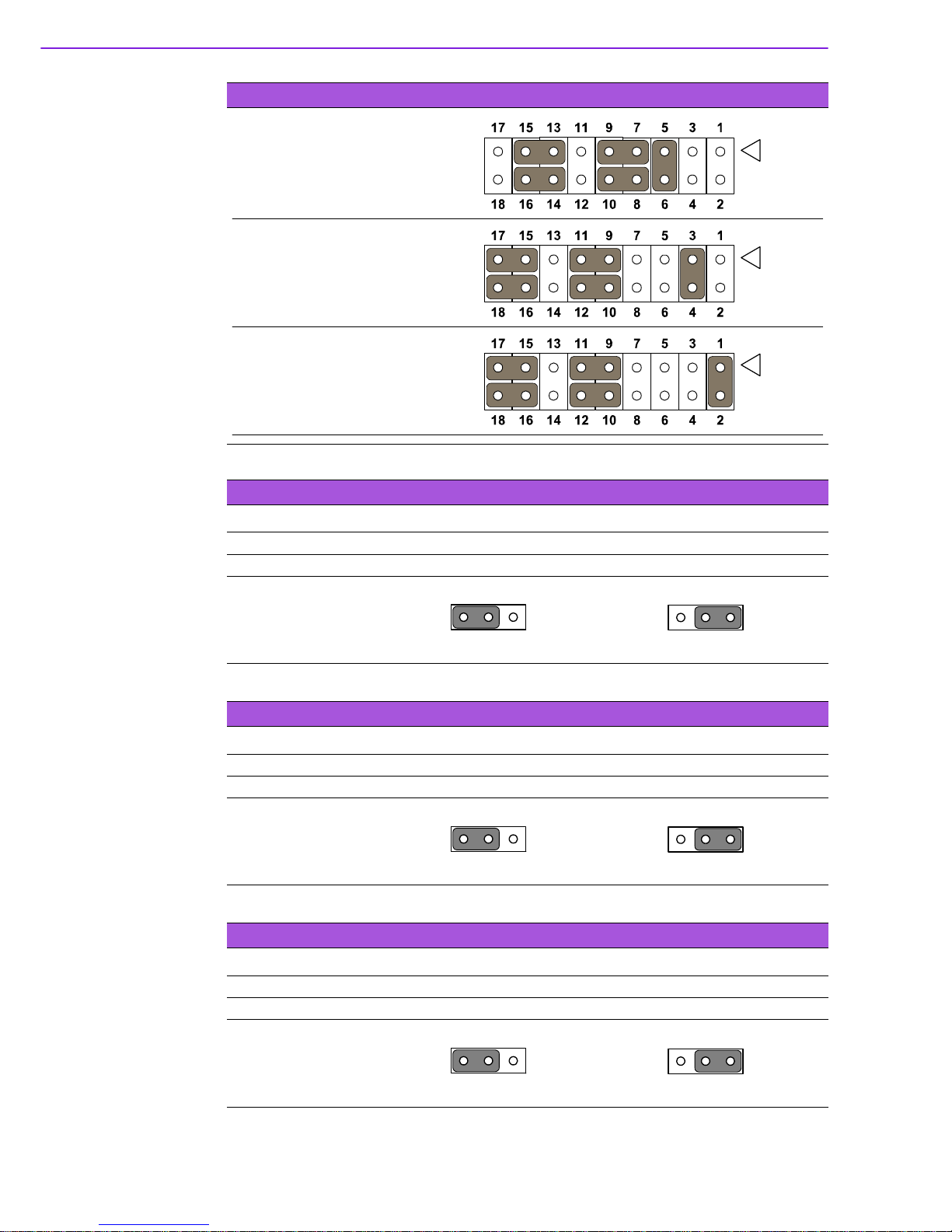
Table 1.4: CMOS1: Clear CMOS
Pins Result
1-2* Keep CMOS data*
2-3 Clear CMOS data
*Default
Table 1.5: J1:LCD Power 3.3 V/5.5 V Selection
Closed Pins Result
1-2* 3.3 V*
2-3 5 V
*Default
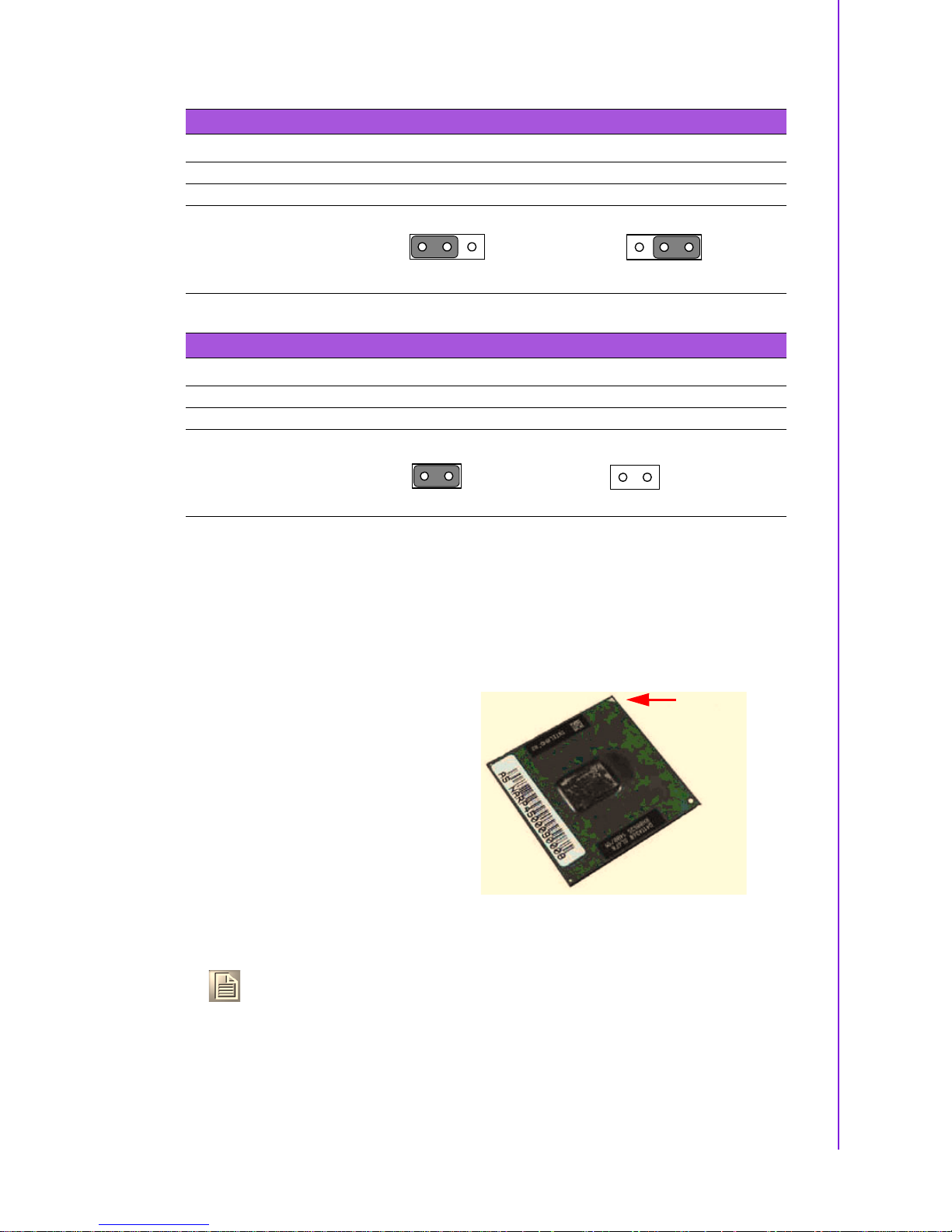
Table 1.6: PSON1: ATX, AT Mode Selection
Closed Pins Result
1-2 AT Mode
2-3* ATX Mode*
*Default
Table 1.3: JSETCOM2: COM2 RS232/422/485 Mode Selection
RS-232 Configuration
(default)
RS-422 Configuration
RS-485 Configuration
1
1
Keep CMOS data Clear CMOS
1
1
3.3 V, 1-2 closed 5 V, 2-3 closed
1
1
AT Mode, 1-2 closed ATX Mode, 2-3 closed
11 AIMB-258 User Manual
Chapter 1 Product Introduction
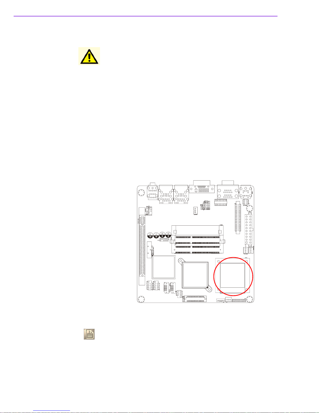
1.12 Central Processing Unit (CPU) for AIMB-258
The motherboard AIMB-258 comes with a surface mount 478-pin Zero Insertion
Force (ZIF) socket designed for the Intel® Pentium® M / Celeron® M processor
(Supports mPGA478M, Micro-FCPGA).
Table 1.7: JWDT1: Watchdog Timer Output Option
Closed Pins Result
1-2 NC
2-3* System Reset*
*Default
Table 1.8: JOBS: HW monitor
Closed Pins Result
1-2* Close: Enable OBS Alarm [Default]
1-2 Open: Disable OBS Alarm
*Default
1
1
NC, 1-2 closed System Reset, 2-3 closed
Close Open
12
12
Take one of the marked corner (with gold
triangle) on the CPU. This mark should
match a specific corner on the socket to
ensure correct installation.
Note!
!
Make sure the AC power is off before you install the CPU.
!
If installing a dual-core CPU, connect the CPU fan cable to the
CPUFAN1 connector to ensure system stability.
Gold Mark
AIMB-258 User Manual 12
1.12.1 Installing the CPU
Caution!
!
Intel® socket 478 Pentium M/ Celeron M CPU with 90nm process
package should come with installation instructions for the CPU,
heatsink, and the retention mechanism. If the instructions in this
section do not match the CPU documentation, follow the latter.
!
Upon purchase of the motherboard, make sure that the PnP cap is
on the socket and the socket contacts are not bent. Contact your
retailer immediately if the PnP cap is missing, or if you see any
damage to the PnP cap/socket contacts/motherboard components.
Your place of purchase or local distributor will shoulder the cost of
repair only if the damage is shipment/transit-related.
!
Keep the cap after installing the motherboard. Your place of purchase or local distributor will process Return Merchandise Authorization (RMA) requests only if the motherboard comes with the cap
on the socket.
!
The product warranty does not cover damage to the socket contacts resulting from incorrect CPU installation/removal, or misplacement/loss/ incorrect removal of the PnP cap.
1. Locate the CPU socket on
the motherboard.
Note!
Before installing the CPU, make sure that the socket box is facing towards you.
13 AIMB-258 User Manual
Chapter 1 Product Introduction
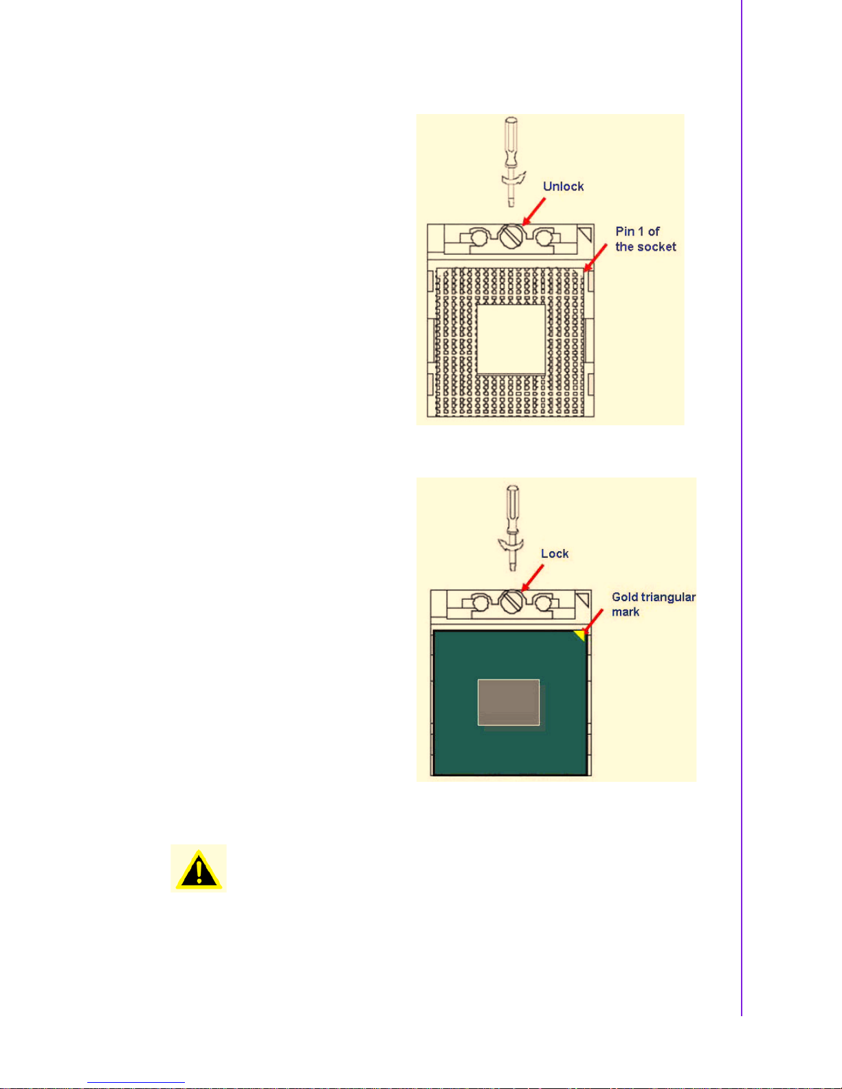
2. The processor socket comes with
a screw to secure the processor,
please unlock the screw first.
3. Position the CPU above the
socket and the gold triangular
mark on the CPU must align with
pin 1 of the CPU socket.
4. Carefully insert the CPU into the
socket until it fits in place ‘Gold
mark’.
5. Turn the screw to the lock
position.
Warning! The CPU fits in only one correct orientation. DO NOT force the CPU into
the socket to prevent bending the connectors on the socket and damaging the CPU.
AIMB-258 User Manual 14
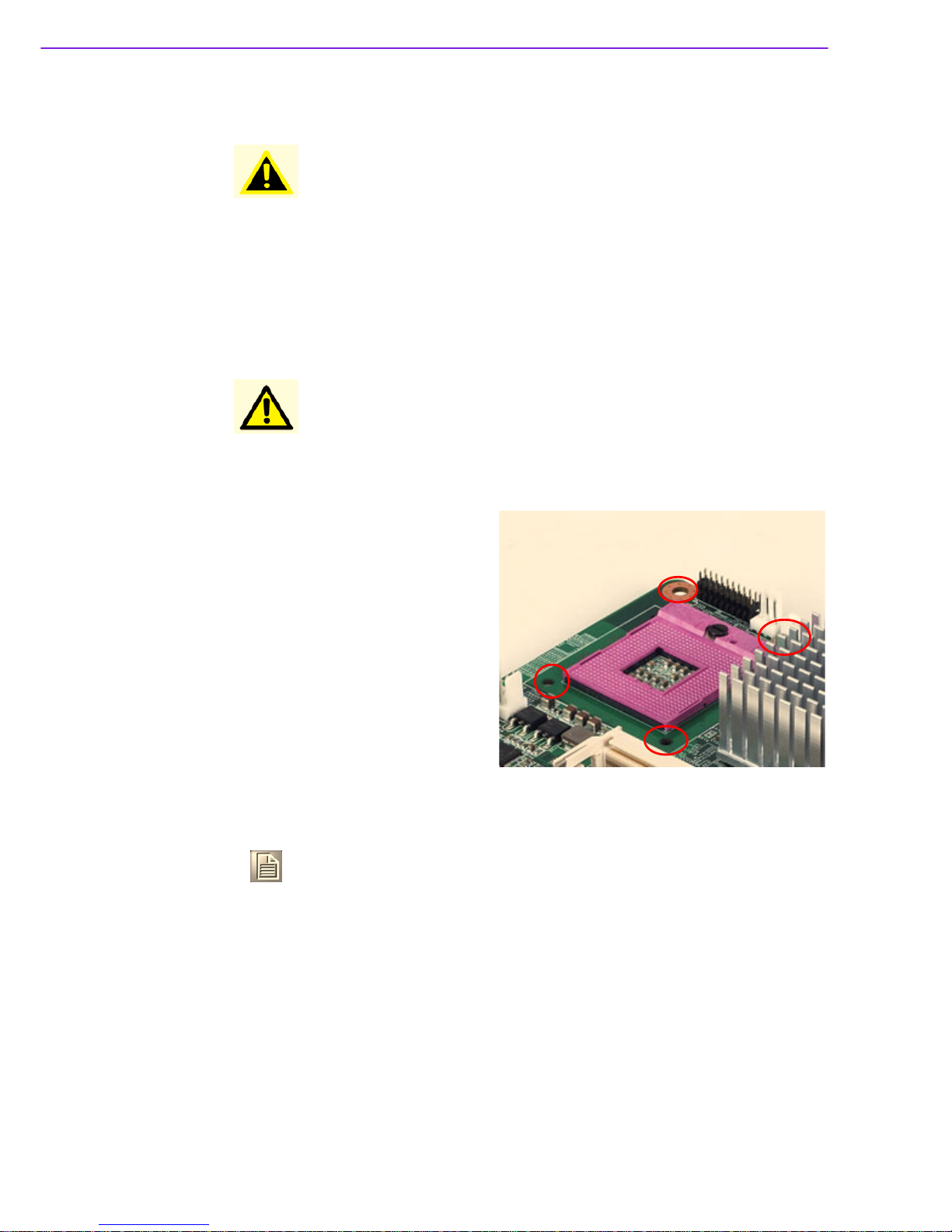
1.12.2 Installing the CPU Heatsink and Fan
The Intel® Pentium® M / Celeron® M processor (supports mPGA478M, MicroFCPGA) requires a specially designed heatsink and fan assembly to ensure optimum
thermal condition and performance.
Warning! After installation, make sure to plug-in the ATX power cable to the moth-
erboard.
Caution! If you purchased a separate CPU heatsink and fan assembly, make
sure that you have properly applied Thermal Interface Material to the
CPU heatsink or CPU before you install the heatsink and fan assembly.
1. Place the heatsink on top of the
installed CPU, making sure that
the four screws match the holes
on the motherboard.
Motherboard Hole
Note! Orient the heatsink and fan assembly such that the CPU fan cable is
closest to the CPU fan connector.
2. Connect the CPU fan cable to the connector on the motherboard labelled
CPUFAN1.
15 AIMB-258 User Manual
Chapter 1 Product Introduction
Caution!
!
Do not forget to connect the fan cables to the fan connectors. Insufficient air flow inside the system may damage the motherboard
components, and hardware monitoring errors can occur if you fail
to plug this connector.
!
These are not jumpers! DO NOT place jumper caps on the fan connectors.

AIMB-258 User Manual 16
1.12.3 Uninstalling the CPU Heatsink and Fan
1. Disconnect the CPU fan cable
from the connector on the
motherboard.
2. Rotate each screw counter- clock-
wise.
3. Carefully remove the heatsink and
fan assembly from the motherboard.
Note! Refer to the documentation in the boxed or stand-alone CPU fan pack-
age for detailed information on CPU fan installation.
17 AIMB-258 User Manual
Chapter 1 Product Introduction
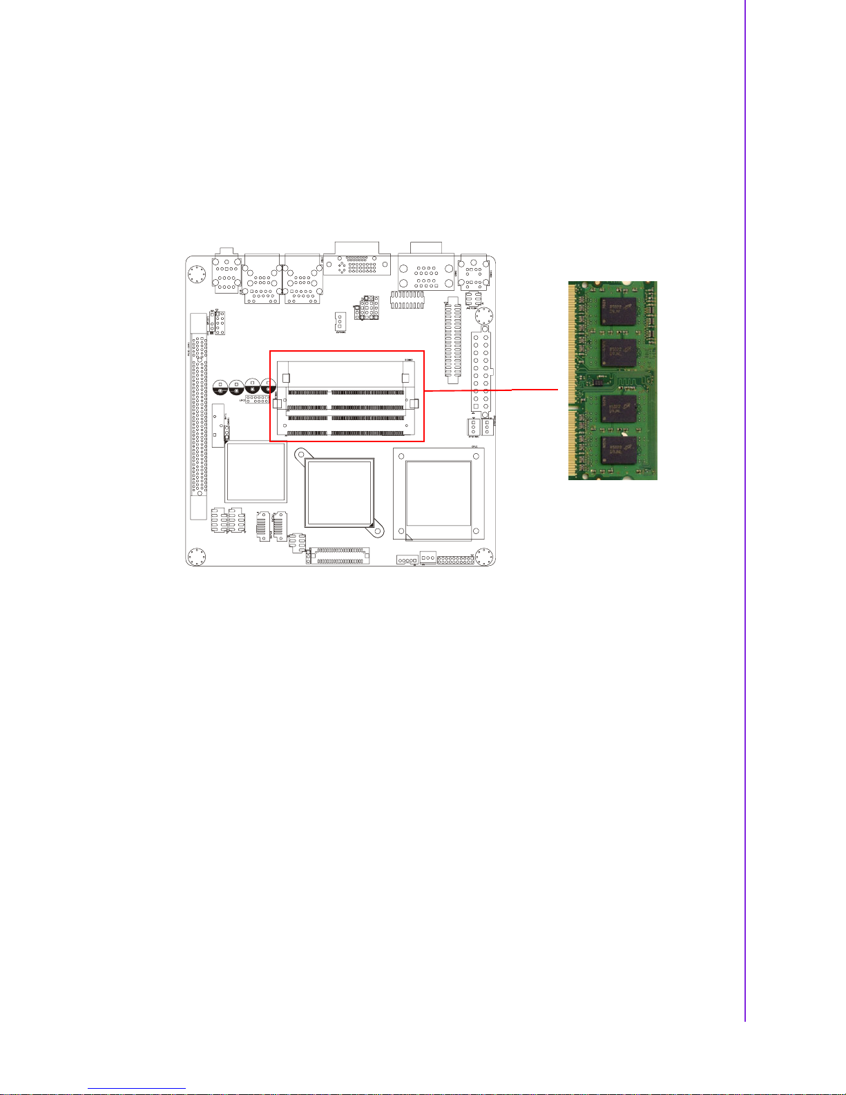
1.13 System Memory
1.13.1 DIMM Sockets Location
The motherboard comes with two 204-pin Double Data Rate 3 (DDR3) Dual Inline
Memory Modules (DIMM) sockets. The following figure illustrates the location of the
sockets:
1.13.2 System Memory
The AIMB-258 has two sockets for 204-pin SODIMMx2.
All these sockets use 1.5 V unbuffered double data rate synchronous DRAMs (DDR
SDRAM). They are available in capacities of 256, 512, and 1024 MB. The sockets
can be filled in any combination with SODIMMs of any size, giving a total memory
size between 256 MB and 2 GB. AIMB-258 does NOT support ECC (error checking
and correction).
1.13.2.1 Memory Installation Procedures
To install SODIMMs, first make sure the two handles of the SODIMM socket are in
the.open. position. i.e., the handles lean outward. Slowly slide the SODIMM module
along the plastic guides on both ends of the socket. Then press the SODIMM module
right down into the socket, until you hear a click. This is when the two handles have
automatically locked the memory module into the correct position of the SODIMM
socket. To remove the memory module, just push both handles outward, and the
memory module will be ejected by the mechanism.
1.13.2.2 Cache Memory
The AIMB-258 supports a CPU with one of the following built-in full speed L2 caches:
2048 MB for Intel Core 2 Duo CPU
The built-in second-level cache in the processor yields much higher performance
than conventional external cache memories.

AIMB-258 User Manual 18
1.13.3 Memory Support List
Table 1.9: SODIMM DDR3
SODIMM DDR3
Brand Size Speed Type ECC Vendor PN AdvantechPNMemory
Transcend 1GB DDR3
1066
SODIMM
DDR3
NTS128MSK
64V1U
96SD31G1066NNTR
SEC K4B1G0846DHCF8(128x8)
2GB DDR3
1066
SODIMM
DDR3
NTS256MSK
64V1U
96SD32G1066NNTR
SEC K4B1G0846DHCF8(128x8)
Apacer RAM
Apacer 1GB DDR3
1066
SODIMM
DDR3
N NA NA ELPIDA J1108BABG-
DJ-E 084909DE7
2GB DDR3
1066
SODIMM
DDR3
N NA NA ELPIDA J1108BABG-
DJ-E 084909D8T
 Loading...