

Page 1

Page 2

Page 3

Copyright
CG Times (based upon Times New Roman), CG Triumvirate, MicroType, and TrueType
are trademarks of the AGFA Monotype Corporation.
PCL, Intellifont, and HP Laser JetII are trademarks of the Hewlett Packard Corporation.
Macintosh is a trademark of the Apple Corporation.
Windows is a trademark of the Microsoft Corporation.
All other brand and product names are trademarks, service marks, registered
trademarks, or registered service marks of their respective companies.
Information in this manual is subject to change without notice and does not represent a
commitment on the part of Datamax-O’Neil Corporation. No part of this manual may be
reproduced or transmitted in any form or by any means, for any purpose other than the
purchaser’s personal use, without the expressed written permission of Datamax-O’Neil
Corporation..
All rights reserved
Copyright © 2014, Datamax-O’Neil
Part Number 88-2364-01
Revision B
Thermal Printer Programmer’s Guide
Page 4

Thermal Printer Programmer’s Guide
Page 5

Table of Contents
Table of Contents
1. Programmer’s Guide
Overview ...............................................................................................1
Scope ...................................................................................................1
Referenced Documents ........................................................................1
Trademark References .........................................................................1
Datamax-O'Neil Commands .................................................................3
PCL Language ......................................................................................3
PCL Command Structure ............................................................................3
Fonts and Symbol Sets Supported ..............................................................6
Printing Unicode Characters in PCL ........................................................11
Datamax-O'Neil Barcode Command Structure .........................................11
PJL (Printer Job Language) Commands ............................................22
Standard PJL Commands ..........................................................................22
PJL File System Commands .....................................................................24
User Font Download via PJL ....................................................................24
PJL FSDELETE Command ......................................................................25
PJL FSINIT Command .............................................................................25
PJL INFO Read-Back Command .............................................................26
PJL JOB Command ..................................................................................28
PJL PERFORM Command .......................................................................28
PJL Head Cleaning Procedure/Command ................................................30
PJL Cutter, Rewinder, and Ribbon Assembly Self-Test Commands .......31
PJL GPIO Self Test ..................................................................................31
PJL GPIO Wrap Test ...............................................................................32
PJL GPIO Read Test ................................................................................32
PJL GPIO Write Test ...............................................................................33
PJL CONFIG PRINTFILE .......................................................................33
PJL CONFIG Command ...........................................................................33
PJL UPGRADE Command .......................................................................34
PJL Variables ............................................................................................35
PJL Internal Variables ..............................................................................42
Defining Internal Variables ......................................................................42
PJL Increment Command .........................................................................42
PJL Date/Time Command ........................................................................43
Hex Transfer Method ................................................................................48
i Thermal Printer Programmer’s Guide
Page 6

Table of Contents
2. Appendix A
Printer Model Printable Print Widths ...................................................51
3. Appendix B
Printer Model Speed ...........................................................................53
Thermal Printer Programmer’s Guide
Page 7

1 Programmer’s Guide
Overview
This Programmer’s Guide provides information about printer specific commands that are
supported by the following printer(s):
•p1115
• p1120n
•p1125
• p1115s
• p1725
•w1110
The Datamax-O'Neil Performance & Workstation Series printers language is based on
Hewlett Packard
barcode printing, Datamax-O'Neil has extended the language by adding barcode specific
commands. Methods exist to print barcodes in a Windows® environment without using
these new commands. Examples include using commercially available barcode fonts or
label design packages.
®
PCL 5e. Because this language does not have native support for
Scope
This document describes Datamax-O'Neil PCL barcode commands, internal variable
commands and various commands specific to thermal print devices. . Knowledge of PCL
is helpful but not required. A full explanation of PCL is beyond the scope of this guide,
please refer to the reference documents listed below.
Referenced Documents
The following documents referenced herein shall apply unless otherwise superseded by
requirements specified elsewhere in this document.
• Hewlett Packard Corporation, "PCL 5 Printer Technical Reference Manual"
• Hewlett Packard Corporation, "HP PCL/PJL Technical Reference Manual"
Trademark References
CG Triumvirate is a trademark of Monotype Imaging Inc.
CG Times, a product of Monotype Imaging Inc., is based on Times New Roman, a U.S.
registered trademark of Monotype Corporation plc.
PCL is a U.S. registered trademarks of Hewlett-Packard Company.
1 Thermal Printer Programmer’s Guide
Page 8

1 | Programmer’s Guide
Microsoft, Windows, and MS-DOS are U.S. registered trademarks of Microsoft
Corporation.
TrueType is a registered trademark of Apple Computer, Inc.
Helvetica and Times Roman are trademarks of Linotype AG and its subsidiaries.
Univers is a U.S. registered trademark of Linotype AG and its subsidiaries.
Antique Olive is a trademark of Monsieur Marcel OLIVE.
Arial is a registered trademark of The Monotype Corporation plc.
Thermal Printer Programmer’s Guide 2
Page 9

Programmer’s Guide | 1
Datamax-O'Neil Commands
There are frequent references to Hewlett Packard’s (HP) PCL Technical Reference
Manual (TRM). This document can be found on HP’s website listed in the Referenced
Documents above. Datamax-O'Neil provides unique commands not within the command
set found in the HP’s PCL TRM. No command defined within this document supersedes
or negates any commands found within the PCL TRM. This does not imply that all
commands defined within the PCL TRM are implemented by the Datamax-O'Neil
Barcode Label Printers. Many commands found within the PCL TRM are irrelevant within
the context of the Barcode Label Printer. Examples of these are commands for selecting
discrete pages sizes such as Letter, Legal, A4, and Executive. Features such as
duplexing and stapling do not currently exist in D-O Barcode Printers and these
commands, if found within the data stream, are silently ignored without error.
PCL Language
PCL Command Structure
General Information
As per Hewlett Packard’s specification on the syntax of escape sequences, there are two
forms of PCL escape sequences: two-character escape sequences and parameterized
escape sequences.
Two character escape sequences have the following form:
<ESC>X
“X” is a character that defines the operation to be performed. Two examples of twocharacter escape sequences are <ESC>E and <ESC>9. The first example resets the
printer to default conditions and the second resets the left and right margins to their
default value. The value of “X” may be any character within the range 0x30 – 0x7E.
Parameterized escape sequences have the following form:
<ESC>X y z1 [+|-]#[.#] z2 [+|-]#[.#] z3 … [+|-]#[.#] Zn[data]
The following characters y, #, zi and data may be optional. The parameterized character
X is within the range of 0x21 – 0x2F. The group character “y” is within the range of 0x60
– 0x7E. Group characters specify the type of control being performed.
Table 1: Parameterized Character <ESC> X...
Character (X) Symbol Purpose
0x21 ! Reserved by D-O for debug firmware
0x22 “ Not Used
0x23 # Not Used
0x24 $ D-O Barcode Parameter
3 Thermal Printer Programmer’s Guide
Page 10
1 | Programmer’s Guide
Character (X) Symbol Purpose
0x25 % PCL Language Parameter
0x26 & PCL Cursor Parameter
0x27 ‘ Not Used
0x28 ( PCL Font Parameter
0x29 ) PCL Font Parameter
0x2A * PCL Graphic Parameter
0x2B + Not Used
0x2C , Not Used
0x2D - Not Used
0x2E . Not Used
0x2F / Not USed
The value field ‘#’ is a group of characters specifying a numeric value. The value is an
ASCII string of characters within the range 0x30 – 0x39. The string may be preceded
with an optional ‘+’ or ‘-‘ sign and may contain a decimal portion separated by the
decimal point. Consider the following example:
<ESC>&l5.81C
This command will set the printer to print 33 lines per label on a 4 inch high label. The
value specified is the number of 1/48 inch increments between rows (5.81 = 4/33 x 48).
The parameter character is any character from the ASCII table within the range of 0x60 –
0x7E. This character specifies the parameter to which the previous value field applies.
This character is used when combining escape sequences as described below in the
section titled “Combining Escape Sequences.”
The Termination Character is any character from the ASCII table within the range 0x40 –
0x5E. This character specifies the parameter to which the previous value field applies.
This character terminates the escape sequence.
The Binary Data is eight-bit data (for example, graphics data, downloaded fonts, etc.).
The number of bytes of binary data is specified by the value field of the escape
sequence. Binary data immediately follows the terminating character of the escape
sequence. Data that is to be encoded into barcode images will be considered as binary
data.
Combining Escape Sequences
All escape sequences that have the same first two characters AFTER the “<ESC>” (the
parameterized and group character) can be combined into a single escape sequence.
For example, the three commands (each begins with the <ESC> character) are of the
type “EC&l”.
Thermal Printer Programmer’s Guide 4
Page 11

Programmer’s Guide | 1
The following:
<ESC>&l1O<ESC>&l2A <ESC>&l5.81C
can be combined into the following single escape sequence:
<ESC>&l1o2a5.81C
In the example above, the capital ‘O’ becomes a lower case ‘o’, the ‘A’ of the second
command becomes an ‘a’ and the ‘EC&l’ are dropped from the second and third
commands. The printer commands are performed in the order they are combined, from
left to right.
Barcode Clipping
PCL normally clips print objects at the dot level on the logical page boundary. Barcodes
clipped in this manner can easily go undetected. Because of this, any portion of a
barcode that falls beyond the boundaries of the logical print area will be dropped and a
shaded rectangle will be printed, inscribing the area within the logical print page where
the barcode would have been. This will provide visual evidence to the user the barcode
has been clipped and is therefore invalid.
Barcodes that are not generated internally by the printer will not be clipped in this
manner and may not be readable by scanning devices.
Cursor Positioning Commands
The PCL cursor refers to the Current Active Position (CAP) which identifies the current
position on the label where a print command begins laying out page data. The cursor can
be moved anywhere within the logical page using a combination of the horizontal and
vertical cursor position commands and control codes. Although there are many different
ways to move the cursor, there are three types of cursor positioning units. These include
PCL Units, Decipoints, and Row/Column units.
The size of a PCL unit is determined by the value specified by the Unit of Measure
command. The format of this command is <ESC>&u#D where # is the number of units
per inch. The “units per inch” value is a discrete value from the following set of values:
{96, 100, 120, 144, 150, 160, 180, 200, 225, 240, 288, 300, 360, 400, 450, 480, 600,
720, 800, 900, 1200, 1440, 1800, 2400, 3600, and 7200}. If the Unit of Measure is not
set, the default value is 300.
A decipoint, in PCL terminology, is 1/720 inch or one-tenth of a PCL point. A PCL point is
exactly 1/72 inch as opposed to a typographic point which is approximately 1/72 inch.
Decipoints are resolution independent. Labels that are designed using units of decipoints
will be resolution independent and are therefore easily portable across PCL printers of
different resolutions. This is the preferred unit of measure in label design.
Cursor Positioning after Printing Barcode
PCL has a procedure for cursor positioning after printing a text character. Set the Current
Active Position (CAP) to the right at a distance equal to the width of that character, ready
5 Thermal Printer Programmer’s Guide
Page 12

1 | Programmer’s Guide
for the next character to be rendered. With raster images, the CAP is moved vertically to
the next dot row below the raster image previously rendered and then returned to the
horizontal start position of the raster image. The terminus CAP of the barcode is
selectable with the commands described below.
Set the Current Active Position (CAP) to the right of the last printed text character at a
distance equal to the width of that character so the next character can be rendered. With
raster images, the CAP is moved vertically to the next dot row below the previously
rendered raster image and returned to the horizontal start position of the raster image.
The terminus CAP of the barcode is selectable with the commands described below.
Orientation and the Influence on Label Dimensions
HP PCL defines the portrait orientation to be the page configuration where the X
dimension moves to the left along the short edge of the paper and the Y dimension
moves downward along the long edge of the paper. This seems perfectly reasonable
until both the label stock and the arbitrary dimensions a label may have on a given roll of
media are considered. As an example, for the common label stock size of 4” by 6”, it is
obvious the label is in the portrait orientation. For 4” by 3” label stock, HP PCL regards
this label as being in the landscape orientation and will automatically rotate the text,
images, rules, and coordinates by 90 degrees to maintain the portrait orientation with
respect to the shorter distance on the side. This may not be what an experienced user of
thermal printers would expect to see. In order for the same image to be produced on a
shorter label, the printer must be programed to produce the image in the landscape
orientation. Orientation takes precedence over label dimensions. If the printer is in the
portrait orientation, HP PCL will rotate the image to align it to the short edge of the label.
This subtle design characteristic may cause problems with users of legacy label printers
therefore we have chosen to modify this behavior to be more in-line with thermal printers.
Fonts and Symbol Sets Supported
Resident Scalable Fonts
The table below provides a list of the 53 resident scalable fonts and the escape
sequence needed to select that font as the current primary font. The <ESC> tag
represents the escape character 0x1B. The <symset> tag represents the symbol set to
use with the selected font (see section 13 below). The <ptsize> tag represents the
requested point size of the font, up to two decimal places. The <pitch> tag represents
horizontal spacing of a fixed pitch font in characters per inch.
Refer to the Symbol Set Mapping Table resident symbol sets. The tags must be replaced
with their appropriate values. Developers may choose to define their own symbol sets.
Note: The resident fonts for your printer may vary in number from those listed in this
table.
Thermal Printer Programmer’s Guide 6
Page 13

Programmer’s Guide | 1
Table 2: Fonts and Escape Sequences
Font Name Escape Sequence
Albertus Medium <ESC>(<symset><ESC>(s1p<ptsize>v0s1b4362T
Albertus Extra Bold <ESC>(<symset><ESC>(s1p<ptsize>v0s4b4362T
Antique Olive <ESC>(<symset><ESC>(s1p<ptsize>v0s0b4168T
Antique Olive Italic <ESC>(<symset><ESC>(s1p<ptsize>v1s0b4168T
Antique Olive Bold <ESC>(<symset><ESC>(s1p<ptsize>v0s3b4168T
Arial <ESC>(<symset><ESC>(s1p<ptsize>v0s0b16602T
Arial Italic <ESC>(<symset><ESC>(s1p<ptsize>v1s0b16602T
Arial Bold <ESC>(<symset><ESC>(s1p<ptsize>v0s3b16602T
Arial Bold Italic <ESC>(<symset><ESC>(s1p<ptsize>v1s3b16602T
Clarendon Condensed Bold <ESC>(<symset><ESC>(s1p<ptsize>v4s3b4140T
Coronet <ESC>(<symset><ESC>(s1p<ptsize>v1s0b4116T
Courier <ESC>(<symset><ESC>(s0p<pitch>h0s0b4099T
Courier Italic <ESC>(<symset><ESC>(s0p<pitch>h1s0b4099T
Courier Bold <ESC>(<symset><ESC>(s0p<pitch>h0s3b4099T
Courier Bold Italic <ESC>(<symset><ESC>(s0p<pitch>h1s3b4099T
Garamond Antiqua <ESC>(<symset><ESC>(s1p<ptsize>v0s0b4197T
Garamond Kursiv <ESC>(<symset><ESC>(s1p<ptsize>v1s0b4197T
Garamond Halbfett <ESC>(<symset><ESC>(s1p<ptsize>v0s3b4197T
Garamond Kursiv Halbfett <ESC>(<symset><ESC>(s1p<ptsize>v1s3b4197T
Letter Gothic <ESC>(<symset><ESC>(s0p<pitch>h0s0b4102T
Letter Gothic Italic <ESC>(<symset><ESC>(s0p<pitch>h1s0b4102T
Letter Gothic Bold <ESC>(<symset><ESC>(s0p<pitch>h0s3b4102T
Marigold <ESC>(<symset><ESC>(s1p<ptsize>v0s0b4297T
CG Omega <ESC>(<symset><ESC>(s1p<ptsize>v0s0b4113T
CG Omega Italic <ESC>(<symset><ESC>(s1p<ptsize>v1s0b4113T
CG Omega Bold <ESC>(<symset><ESC>(s1p<ptsize>v0s3b4113T
CG Omega Bold Italic <ESC>(<symset><ESC>(s1p<ptsize>v1s3b4113T
CG Times <ESC>(<symset><ESC>(s1p<ptsize>v0s0b4101T
CG Times Italic <ESC>(<symset><ESC>(s1p<ptsize>v1s0b4101T
CG Times Bold <ESC>(<symset><ESC>(s1p<ptsize>v0s3b4101T
CG Times Bold Italic <ESC>(<symset><ESC>(s1p<ptsize>v1s3b4101T
Times New Roman <ESC>(<symset><ESC>(s1p<ptsize>v0s0b16901T
Times New Roman Italic <ESC>(<symset><ESC>(s1p<ptsize>v1s0b16901T
Times New Roman Bold <ESC>(<symset><ESC>(s1p<ptsize>v0s3b16901T
7 Thermal Printer Programmer’s Guide
Page 14
1 | Programmer’s Guide
Font Name Escape Sequence
Times New Roman Bold Italic <ESC>(<symset><ESC>(s1p<ptsize>v1s3b16901T
Univers Medium <ESC>(<symset><ESC>(s1p<ptsize>v0s0b4148T
Univers Medium Italic <ESC>(<symset><ESC>(s1p<ptsize>v1s0b4148T
Univers Bold <ESC>(<symset><ESC>(s1p<ptsize>v0s3b4148T
Univers Bold Italic <ESC>(<symset><ESC>(s1p<ptsize>v1s3b4148T
Univers Condensed Medium <ESC>(<symset><ESC>(s1p<ptsize>v4s0b4148T
Univers Condensed Medium Italic <ESC>(<symset><ESC>(s1p<ptsize>v5s0b4148T
Univers Condensed Bold <ESC>(<symset><ESC>(s1p<ptsize>v4s3b4148T
Univers Condensed Bold Italic <ESC>(<symset><ESC>(s1p<ptsize>v5s3b4148T
Symbol <ESC>(19M<ESC>(s1p<ptsize>v0s0b16686T
Wingdings <ESC>(579L<ESC>(s1p<ptsize>v0s0b31402T
OCR A <ESC>(<symset><ESC>(s1p<pitch>h0s0b23584T
OCR A Fixed <ESC>(<symset><ESC>(s0p<pitch>h0s0b23584T
OCR B <ESC>(<symset><ESC>(s1p<pitch>h0s0b23590T
OCR B Fixed <ESC>(<symset><ESC>(s0p<pitch>h0s0b23590T
VeraMono <ESC>(<symset><ESC>(s1p<ptsize>v3s0b23410T
CG Triumvirate <ESC>(<symset><ESC>(s1p<ptsize>v0s0b26708T
CG Triumvirate Bold Condensed <ESC>(<symset><ESC>(s1p<ptsize>v0s0b26714T
Symbol Sets
Symbol sets are used to map character codes to the associated character image. The
most familiar symbol set is the ASCII character mapping for characters occupying the
character codes ranging from 0x20, which is the space character, through 0x7E, which is
the tilde ‘~’ character. These symbol sets are used to support the internationalization of
labels.
Table 3: Symbol Sets
PCL
Symbol Set
10U PC8 PC-8 PC-8
8U ROMAN8 Roman-8 Roman-8
PJL Symbol
Name
Control
Panel Name
Symbol Set Description
4U ROMAN9 Roman-9 Roman-9
0N ISOL1 ISO-L1 ISO 8859-1 Latin 1
2N ISOL2 ISO-L2 ISO 8859-2 Latin 2
4N ISOL4 ISO-L4 ISO 8859-4 Latin 4
5N ISOL5 ISO-L5 ISO 8859-9 Latin 5
Thermal Printer Programmer’s Guide 8
Page 15

Programmer’s Guide | 1
PCL
Symbol Set
6N ISOL6 ISO-L6 ISO 8859-10 Latin 6
9N ISOL9 ISO-L9 ISO 8859-15 Latin 9
26U PC775 PC-775 PC-775
5M PSMATH PS MATH PS-Math
8M MATH8 MATH-8 Math-8
15U PIFONT IP FONT Pi Font
6J MSPUBL MS PUBL Microsoft Publishing
11U PC8DN PC-8 DN PC-8 Danish/Norwegian
12U PC850 PC-850 PC-850 Multilingual
17U PC852 PC-852 PC-852
13U PC858 PC-858 PC-858 Multilingual
9T PC8TK PC-8 TK PC-Turkish
9J PC1004 PC-1004 PC-1004
19U WINL1 WIN L1 Windows CP1252 Latin 1
9E WINL2 WIN L2 Windows CP1250 Latin 2
PJL Symbol
Name
Control
Panel Name
Symbol Set Description
5T WINL5 WIN L5 Windows CP1254 Latin 5
19L WINBALT WINBALT Windows CP1257 Baltic
7J DESKTOP DESKTOP Desktop
10J PSTEXT PS TEXT PS Text
1U LEGAL LEGAL Legal
1E ISO4 ISO-4 United Kingdom Code Set
0U ISO6 ISO-6 7 Bit ASCII Code Set
0S ISO11 ISO-11 7 Bit Western Europe (Swedish)
0I ISO15 ISO-15 7 Bit Western Europe (Italian)
2S ISO17 ISO-17 7 Bit Western Europe (Spanish)
1G ISO21 ISO-21 7 Bit Western (German)
0D ISO60 ISO-60 7 Bit Western Europe (Norwegian)
1F ISO69 ISO-69 7 Bit Western Europe (French)
9U WIN30 WIN 3.0 Windows CP1252 (obsolete)
12J MCTEXT MC TEXT MC Text
18N UCS2 UCS-2 Unicode 2 Byte Encoding
0E ROMANEXT RomanExt Roman Extensions
579L WINGDINGS WindDings Wingdings Font
14L ZAPDINGBATS ZapDingBats Windows Dingbats Font
9 Thermal Printer Programmer’s Guide
Page 16
1 | Programmer’s Guide
12U
PC85
PCL
Symbol Set
19M SYMBOL Symbol Symbol Font
PJL Symbol
Name
Control
Panel Name
Symbol Set Description
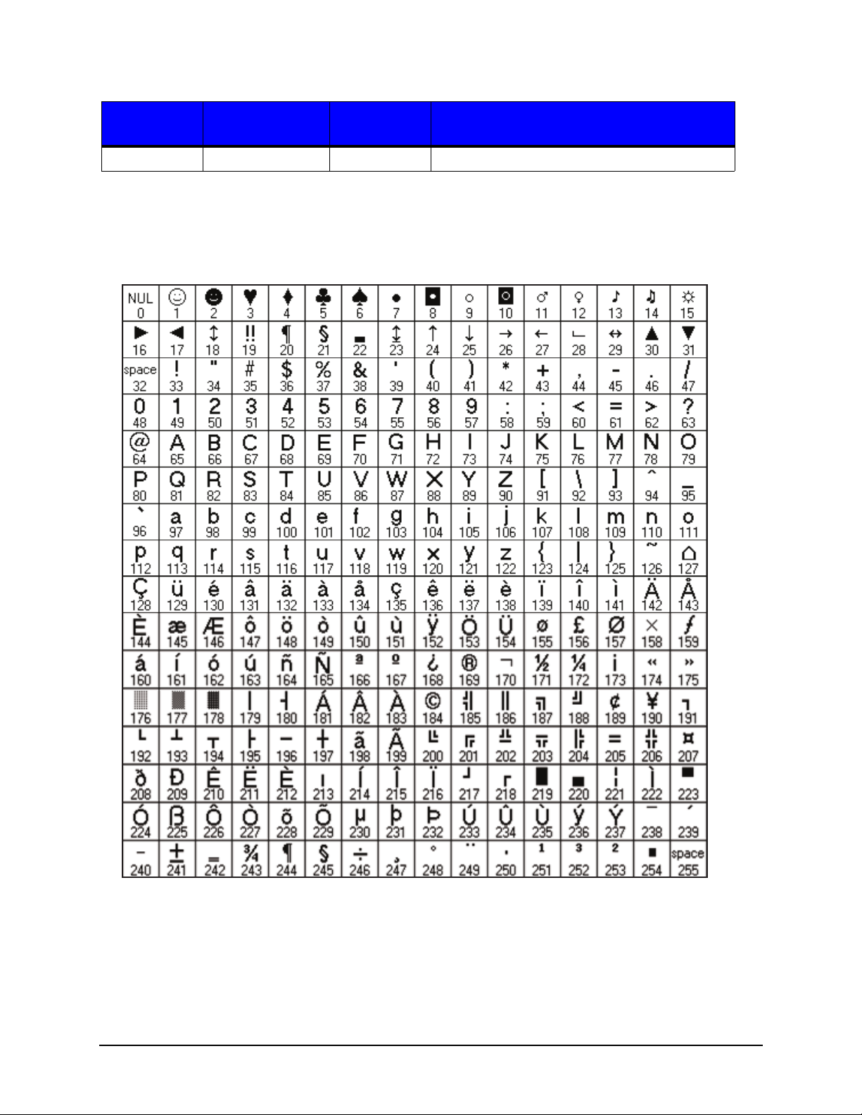
The table below (PC-850 Symbol Set) is an example of character code mapping and the
character image associated with that code.
Figure: 1 - 1 PC-850 Symbol Set
Thermal Printer Programmer’s Guide 10
Page 17

Programmer’s Guide | 1
Printing Unicode Characters in PCL
To print Unicode characters, the symbol set 18N (UCS-2) should be used to set handling
to Unicode mapping together with UTF-8 text parsing method. Refer to the following
syntax:
<ESC>&t83P<ESC>(18N<ESC>(sn1Tdata …
The 83P in <ESC>&t command signifies the UTF-8 text parsing method. The 18N in
<ESC>( command sets the Unicode mode. The n1T is used to select a font in the
<ESC>(s command where n1 is the typeface id of the font. Immediately following are the
characters to print in UTF-8 format. Refer to the example below:
<ESC>&t83P<ESC>(18N<ESC>(s1p16v0s0b9999T<D8><B6><CE><B1><E0><B
8><82><EA><B0><95><E8><90><81>
This prints the characters “ض α?강萁“ (an Arabic, Greek, Thai, Korean and Chinese
symbol) assuming the font supports all of these characters. The font selection command
parameters are “1p” for proportional spacing, “16v” for point size of 16, “0s” for no italic,
“0b” for no bold and “9999T” for typeface ID.
Datamax-O'Neil Barcode Command Structure
Command Structure Syntax
As stated earlier, printer commands are performed in the order that they are combined,
from left to right. There are several barcode parameters that are only relevant to a subset
of the total number of barcodes provided.
All Datamax-O'Neil barcodes and their support parameters will begin with the following
sequence:
<ESC>$b... 0x1b 0x24 0x62
There are several escape commands associated with barcodes. Any escape command
that modifies a property of a barcode will only affect the currently selected barcode. For a
label design with multiple barcode types, modification of one or more barcode properties
does not affect the properties of any other barcode type.
The following commands illustrate how one might handle modifying the default
parameters for multiple barcode types on a single label. Note that the examples below
have line numbers. For ease of reading each line is separated by a carriage return and
line feed. When sending this data to the printer, all the lines in the examples should NOT
have a carriage return and line feed except where you see the symbol “CRLF”. The
“CRLF” symbol indicates a carriage return/line feed combination should be inserted into
the data stream. The “<ESC>” symbol indicates the escape character (hex value 0x1B)
should be inserted into the data stream.
11 Thermal Printer Programmer’s Guide
Page 18
1 | Programmer’s Guide
Table 4: Example of Printing Barcodes (Compressed Commands)
Commands Description
<ESC>%-12345X@PJL SET RESOLUTION =
CRL
300
@PJL SET PAPERWIDTH=2880
@PJL SET PAPERLENGTH=2880
@PJL ENTER LANGUAGE = PCL
F
CRL
F
CRL
F
CRL
F
Reset the printer and enter into PJL mode, Set the
resolution to 300 DPI
Set the label width to 2880 decipoints (4 inches)
Set the label length to 2880 decipoints (4 inches)
Select the PCL emulation
<ESC>&a2160h720v270P Set the horizontal cursor position at 2160
decipoints (3 inches) and the vertical cursor
position at 720 decipoints (1 inch) and set the
writing direction at 270 degrees counter clockwise
from horizontal (down the label).
<ESC>$b1030c360h2a10W9876543210
Select barcode 1030 (Code 128 w/ Auto select).
Set the barcode height of this barcode to 360
decipoints and enable autoprint w/ checksum
(human readable). With the currently selected
barcode (1030), print the data 9876543210 (10
bytes of data)
<ESC>&a0p720h540V Set the writing direction to 0 degrees, the horizontal
cursor position at 720 decipoints horizontally (1
inch) and 540 decipoints vertically (¾ inch).
<ESC>$b1061c360h0a10W1234567890 Select barcode 1061 (Interleave 2 of 5 w/ Bearer
Bars), the height of the barcode to 360 decipoints
(1/2 inch), no autoprint and print the following 10
bytes: 1234567890
<ESC>E Reset PCL (this causes any imaged data to be
printed)
<ESC>%-12345X Reset the printer and wait for more PJL commands
Table 5: Example of printing Barcodes (Uncompressed Commands
Commands Descriptions
<ESC>%-12345X@PJL SET RESOLUTION =
CRL
300
@PJL SET PAPERWIDTH=2880
@PJL SET PAPERLENGTH=2880
@PJL ENTER LANGUAGE = PCL
F
CRL
F
CRL
F
CRL
F
<ESC>&a2160H Set the horizontal cursor position to 2160
<ESC>&720V
Reset the printer and enter PJL mode
Set the label width to 2880 decipoints (4 inches)
Set the label length to 2880 decipoints (4 inches)
Select the PCL emulation
decipoints
Set the vertical cursor position to 720 decipoints
Thermal Printer Programmer’s Guide 12
Page 19

Programmer’s Guide | 1
Commands Descriptions
<ESC>&a270P
<ESC>$b1030C Select barcode number 1030 (Code 128 /w Auto
<ESC>$b360H Set the barcode height to 360 decipoints (½ inch)
<ESC>$b2A Enable barcode autoprint with checksum
<ESC>$b10W9876543210 With the current barcode (1030) print the 10 bytes
<ESC>&0P
<ESC>&a720H Set the horizontal cursor position to 720 decipoints
<ESC>&a540V
<ESC>$b1061C
<ESC>$b360H
<ESC>$b0A
Set the writing direction to 270 degrees counter
clockwise from horizontal
select)
of data: 9876543210
Set the writing direction at 0 degrees.
Set the vertical cursor position to 1440 decipoints
Select barcode number 1061 (Interleave 2 of 5)
Set the barcode height to 180 decipoints (¼ inch)
Disable barcode autoprint for this barcode
<ESC>$b10W0123456789 With the current barcode type (1061) print data
0123456789
<ESC>E Reset PCL (print the imaged data)
<ESC>%-12345X Reset the printer and wait for more PJL commands
Comparing the two tables above there is a noticeable difference in the amount of data
saved by compressing the commands. In general, three bytes for each combined
command will be saved. This becomes significant with larger, more complex labels,
especially if the labels will be stored in the printer as macros.
Enable/Disable Barcode Autoprint
The following command will enable or disable human readable autoprint of the barcode
data:
<ESC>$b#A 0x1b 0x24 0x62 <0|1|2> 0x41
The command will affect only those barcodes with a human readable component. The
following arguments are valid:
0 – Disable human readable text
1 – Enable human readable text
2 – Enable human readable with checksum information
Note: The autoprint field is considered part of the barcode object. It is implied that when
the height of the barcode is specified, the height of the autoprint is included in that
barcode height. For example, if a Code 3 of 9 barcode is selected with autoprint in the
normal orientation and has a height of 1 inch, the height is measured from the top of the
barcode to the baseline of the autoprint text.
13 Thermal Printer Programmer’s Guide
Page 20

1 | Programmer’s Guide
Select Guard Boxes/Bars
The following will select guard boxes or bars on barcodes that support them:
<ESC>$b#B 0x1b 0x24 0x62 <value> 0x42
Select Barcode Type
The following will select the current barcode type:
<ESC>$b#C 0x1b 0x24 0x62 <value> 0x43
Note that all barcode commands below operate on the currently selected barcode. The
table below contains the list of barcodes and their numerical values.
Set Barcode Data Delimiter
The following will select the data delimiter for the currently selected barcode:
<ESC>$b#D 0x1b 0x24 0x62 <value> 0x44
The value parameter is the ASCII value of the character to be used as a delimiter. Refer
to the print barcode data below for a description of the “Print Barcode Data” command
and note how this command extends the capabilities of the “Print Barcode Data”
command. The following combined1 command will select the Code 39 barcode, set the
Data Delimiter to the tilde character ‘~’ (ASCII 127) and print the barcode with the data
‘0123456789’.
<ESC>$b1000c126d0W0123456789~
In this example the value of the width command is set to zero. This will instruct the printer
to read data after the ‘W’ command until the data delimiter (~) is found. The delimiter is
discarded and not printed. The default value for the data delimiter is the carriage return
(ASCII 13). The delimiter value must be a value not found in the data set being encoded
in the barcode.
Select Error Correction Capacity
The following will set the ECC for 2D barcodes - Datamatrix, PDF417, QR and Aztec,
where:
<ESC>$b#E 0x1b 0x24 0x62 <value> 0x45
1. See Section on Combined Escape Sequences.
Thermal Printer Programmer’s Guide 14
Page 21

Values:
Aztec (0-4) PDF 417 (0-8)
Programmer’s Guide | 1
0 - 23%
1 - 10%
2 - 23%
3 - 36%
4 - 50%
Datamaxtrix (1)
1 - ECC 200
QR Code (1-4)
1 - High Density 7%
2 - Standard Density 15%
3 - High Reliablity 25%
4 - Ultra Reliabilty 30%
For Maxicode barcodes:
<ESC>$b#E 0x1b 0x24 0x62 <value> 0x45
Where n=
2 = Structured carrier, numeric, US
3 = Structured carrier, alphanumeric, non US
4 = Standard
5 = Full ECC
6 = Reader program
0 - 2 Codewords
1 - 4 Codewords
2 - 8 Codewords
3 - 16 Codewords
4 - 32 Codewords
5 - 64 Codewords
6 - 128 Codewords
7 - 256 Codewords
8 - 512 Codewords
Select Barcode Terminating Current Active Position
The following will place the cursor position at the location depicted in the diagram below.
This escape sequence must be sent prior to sending any data that is to appear in the
barcode.
<ESC>$b#F 0x1b 0x24 0x62 <value> 0x46
Select Barcode Height (Decipoints)
The following will set the barcode height in decipoints with 1 decimal.
<ESC>$b#H 0x1b 0x24 0x62 <value> 0x48
If the barcode auto print is enabled prior to sending the barcode data, the height of the
barcode will include the height of any human readable text if enabled. The number of
pixels used in the barcode height will always be rounded. As an example, if the barcode
height is specified to be 97 decipoints, the number of dots used on a 300 DPI printer is
[(97 x 300)/720 = 40.417] and will round down to 40 dots. If the height is specified to be
98 [(98 x 300)/720 = 40.833] the number of dots will be 41. The default barcode height is
720 decipoints (1 inch) for linear barcodes.
Figure: 1 - 2 Terminating Current Active Position
15 Thermal Printer Programmer’s Guide
Page 22

1 | Programmer’s Guide
Select Barcode Height (PCL Units)
The following will set the barcode height in PCL units with 1 decimal. The number of
codewords per line are as follows: PDF417 (0-30), Micro PDF (0-4), QR Code (0-40). For
Datamatrix it is the symbol size value per the table below.
<ESC>$b#J 0x1b 0x24 0x62 <value> 0x48
1 - 10x10 7 - 22x22 13 - 44x44 19 - 88x88 25 - 8x18
2 -12 x12 8 - 24x24 14 - 48x48 20 - 96x96 26 - 8x32
3 - 14x14 9 - 26x26 15 - 52x52 21 - 104x104 27 - 12x26
4 - 16x16 10 - 32x32 16 - 64x64 22 - 120x120 28 - 12x36
5 - 18x18 11 - 36x36 17 - 72x72 23 - 132x132 29 - 16x36
6 - 20x20 12 - 40x40 18 - 80x80 24 - 144x144 30 - 16x48
If the barcode auto print is enabled prior to sending the barcode data, the height of the
barcode will include the height of any human readable text if enabled. The number of
pixels used in the barcode height will always be rounded. As an example, if the barcode
height is specified to be 97 decipoints, the number of dots used on a 300 DPI printer is
[(97 x 300)/720 = 40.417] and will round down to 40 dots. If the height is specified to be
98 [(98 x 300)/720 = 40.833] the number of dots will be 41. The default barcode height is
720 decipoints (1 inch) for linear barcodes.
Select Narrow Bar Width (Decipoints)
The following command will set the width of a narrow bar in Decipoints (720/inch) with
one decimal:
<ESC>$b#M 0x1b 0x24 0x62 <value> 0x4d
An example of this command might be:
<ESC>$b9.6M
This will set the width of the narrow bar to 9.6 Decipoints which is equivalent to 4 dots at
300 dpi or 8 dots at 600dpi. This command will round for example (2*300)/720 = 0.833
Thermal Printer Programmer’s Guide 16
Page 23

Programmer’s Guide | 1
and will round up to 1 dot. (3*300)/720 = 1.25 and will round down to 1 dot. (4*300)/720=
1.667 and will round up to 2 dots. The printer will not ensure that the narrow element
width is within specification for that barcode type. The default narrow element width will
be defaulted to a reasonable value for each barcode type.
Select Narrow Bar Width (Dots)
The following command, like the one above, will set the width of a narrow bar in PCL
units.
<ESC>$b#N 0x1b 0x24 0x62 <value> 0x4e
The PCL unit defaults to 300 units per inch. This may be modified with the <ESC>&u#D
command. See the PCL Technical Reference Manual for details about this command. If
the user’s environment contains printers with various print densities, refer to the section
titled “Select Barcode Width using Decipoints.”
Select Barcode Anchor
The following will select the point that will serve as the barcode anchor point that
coincides with the beginning cursor position:
<ESC>$b#O 0x1b 0x24 0x62 <value> 0x4F
The diagram below provides the value used to designate where the barcode anchor
point will be. The value may be modified at any time for any subsequent barcodes that
follow.
Many barcodes require quiet zones. A quiet zone is the area immediately surrounding
the barcode and must be free of any text or graphic images. It is the user’s responsibility
to insure no text, lines, boxes or graphic images of any kind encroach within the quiet
zone. Failure to do so could render the barcode unreadable by some barcode scanners.
Figure: 1 - 3 Barcode Anchor Point
Select Leading and Trailing Quiet Zone Size
The following command will set the quite zone size
<ESC>$b#Q 0x1b 0x24 0x62 <value> 0x51
17 Thermal Printer Programmer’s Guide
Page 24

1 | Programmer’s Guide
Select Barcode Ratio
The following command will set the wide-to-narrow bar ratio.
<ESC>$b#R 0x1b 0x24 0x62 <value> 0x52
The value of ‘#’ may be one of the following:
1 = 2:1
2 = 7:3
3 = 5:2
4 = 3:1
Any other value will default to the standard ratio of the currently selected barcode. This
command only affects Code 3 of 9 and Interleaved 2 of 5.
Print Barcode Data
The following command will use the provided data in this sequence to print the currently
selected barcode.
<ESC>$b#W 0x1b 0x24 0x62 <value> 0x57
The number of data bytes is specified in the <value> parameter field. As an example:
<ESC>$b1000C <ESC>$b10W1234567890THIS IS A BARCODE
The following condensed command is also valid:
<ESC>$b1000c10W1234567890THIS IS A BARCODE
Either command will select the Code 39 Barcode as the default barcode then send the
10 characters following the barcode selection command to the Code 39 module for
rendering at the current cursor position. It will be followed by the text “This is a Barcode”
using the currently selected font (not the autoprint typeface). A width value of zero will
trigger the data scanning process to read barcode data until the barcode data delimiter is
encountered. Refer to the section titled “Set Barcode Data Delimiter” for details of the
“Barcode Data Delimiter Command”.
Print Internal Variable Barcode Data
The following command will use data described by internal variables such as Date, Time
or Counting fields:
<ESC>$b#Y 0x1b 0x24 0x62 <value> 0x59
Since the length of the data at any given moment is unknown by the host, this provides a
means for internal data fields to be processed into barcodes. Refer to section “PJL GPIO
Write Test” for the details on usage of internal data fields and for a “<value>” parameter
to specify in the command.
Default Barcode Parameters
Several of the barcodes provided by the printer are user configurable including line
width, barcode heights and the bar/space ratio. The table above contains the default
values for the user configurable parameters. Note that every effort has been made to
Thermal Printer Programmer’s Guide 18
Page 25

Programmer’s Guide | 1
insure every resident barcode produced by Datamax-O'Neil Barcode Printers are within
industry specification. Upon deciding to modify these values, be aware that some
barcode scanners may not be able to property decode the barcode. Also note that any
modified values are not stored permanently in the printer. Once the job of labels has
completed, the default values are restored.
Table 6: Barcode Defaults
Barcode IDBarcode Description Narrow Element
Width
Default
Ratio
Default Height
Dots Decipoints Dots Decipoints
1000
(Default)
1001
1010 UPC A 4 9.6 N/A 300 720
1020 UPC E 4 9.6 N/A 300 720
1021 UPC/EAN Add-On 4 9.6 N/A 300 720
1030 Code 128 Auto Select 3 7.2 N/A 150 360
1031 Code 128 Set A 3 7.2 N/A 150 360
1032 Code 128 Set B 3 7.2 N/A 150 360
1033 Code 128 Set C 3 7.2 N/A 150 360
1040 EAN 8 4 9.6 N/A 240 576
1050 EAN 13 4 9.6 N/A 300 720
1060 Interleaved 2 of 5 Mod 10 3 7.2 3:1 150 360
1061 Interleaved 2 of 5 Bearer
1062 Interleaved 2 of 5 3 7.2 3:1 150 360
1070 GS1-128 4 9.6 N/A 450 1080
Code 3 of 9
Code 3 of 9 Extended
Bars
4 9.6 3:1 150 360
4 9.6 3:1 150 360
3 7.2 3:1 150 360
1080 Codabar 3 7.2 N/A 150 360
1090 UK Plessey 3 7.2 N/A 150 360
1091 MSI Plessey Mod 10 3 7.2 N/A 150 360
1100 Code 93 3 7.2 N/A 150 360
1110 HIBC Code 39 3 7.2 N/A 150 360
1111 HI B C C ode 128 3 7.2 N/ A 150 360
1120 Telepen 3 7.2 N/A 150 360
1130 GS1 Databar (linear only) 3 7.2 N/A 141 338.4
1131 GS1 Databar Expanded
(linear only)
1500 Postnet 6 14.4 N/A 38 91.2
1510 Planet 6 14.4 N/A 38 91.2
1520 FIM 9 21.6 N/A 187 448.8
3 7.2 N/A 144 345.6
19 Thermal Printer Programmer’s Guide
Page 26
1 | Programmer’s Guide
Barcode IDBarcode Description Narrow Element
Width
Default
Ratio
Default Height
Dots Decipoints Dots Decipoints
1530 USPS Intelligent Mail
(OneCode)
5 12 N/A 45 108
Table 7: 2D Barcodes
2000 QR Code Auto
2010 PDF 417
2020 Micro PDF
2030 Datamatrix
2040 UPS MaxiCode
2050 Aztec
Table 8: Valid Barcode Data
Barcode ID Barcode Description Length Valid Characters Checksum
1000 Code 3 of 9 1-75 0-9, A-Z, $,%,+,-,.,/,space No
1001 Code 3 of 9 Extended 1-66 ASCII 0-0x7F No
1010 UPC A 1-11 0-9 Yes
1020 UPC E 1-7 0-9 Yes
1021 UPC/EAN Add-On 2 or 5 0-9 Yes
1030 Code 128 Auto Select 1-79 ASCII 0-0x7F Yes
1031 Code 128 Set A 1-79 ASCII 0-0x7F Yes
1032 Code 128 Set B 1-79 ASCII 0-0x7F Yes
1033 Code 128 Set C 1-79 ASCII 0-0x7F Yes
1040 EAN 8 1-7 0-9 Yes
1050 EAN 13 1-12 0-9 Yes
1060 Interleaved 2 of 5 Mod 10 1-89 0-9 Yes
1061
1062 Interleaved 2 of 5 1-89 0-9 No
1070 GS1-128 1-79 ASCII 0x20-0x7F
1080 Codabar 1-60 0-9, A-D No
1090 UK Plessey 1-65 0-9, A-F No
1091 MSI Plessey Mod 10 1-55 0-9 Yes
Interleaved 2 of 5 Bearer
Bars
1-89 0-9 Yes
Yes
The leading AI value must be
placed in square brackets
and a trailing checksum must
be included.
1100 Code 93 1-107 ASCII 0x20-0x7F No
Thermal Printer Programmer’s Guide 20
Page 27
Programmer’s Guide | 1
Barcode ID Barcode Description Length Valid Characters Checksum
1110 HIBC Code 39 1-36 0-9, A-Z, $,%,+,-,.,/,space Yes
1111 HIBC Code 128 1-36 0-9, A-Z, $,%,+,-,.,/,space Yes
1120 Telepen 1-30 ASCII 0x20-0x7F Yes
1130 GS1 Databar (linear only) 1-13 0-9 Yes
1131 GS1 Databar Expanded
(linear only)
1500 Postnet 1-38 0-9 Yes
1510 Planet 1-38 0-9 Yes
1520 FIM 1 A-D No
1530 USPS Intelligent Mail
(OneCode)
2000 QR Code Auto 1-256 ASCII 0x20-0x7F Yes
2010 PDF 417 1-256 Full ASCII (0 – 0xFF) Yes
2020 Micro PDF 1-256 Full ASCII (0 – 0xFF) Yes
2030 Datamatrix 1-256 Full ASCII (0 – 0xFF) Yes
2040 UPS MaxiCode 1-138 Alphanumeric, ASCII 0x1E,
2050 Aztec 1-256 Full ASCII (0 – 0xFF) Yes
1-45 ASCII 0x20-0x7F Yes
20 0-9 Yes
Yes
0x1D,0x04,[,),>
BarcodeSamples
The following sequence will print a code 3 of 9 barcode, height of 300 dots (includes
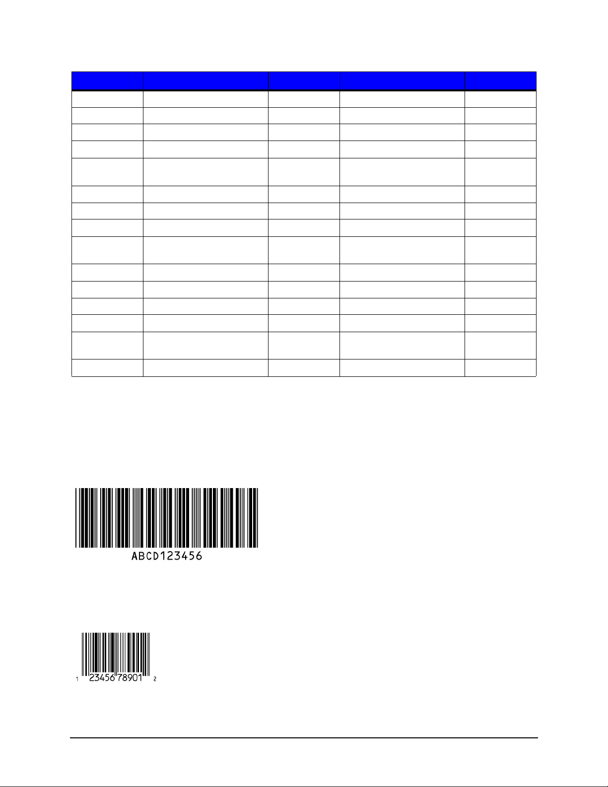
text), narrow bar width 4 dots and data “ABCD123456”.
<ESC>$b1000c300j4n10WABCD123456
The following sequence will print a UPC E barcode, human readable text, narrow bar
width 3 dots, 200 dots height and data “12345678901”
<ESC>$b1010c1a3n200j11W12345678901
21 Thermal Printer Programmer’s Guide
Page 28

1 | Programmer’s Guide
The following sequence will print a QR Code (Auto) barcode with error correction
capacity of 2, height 10 units, anchor position bottom left and data “This is a test, this is
only a test.”
<ESC>$b2000c2e10j0o36WThis is a test, this is only a test.
The following sequence will print a UPS Maxicode with anchor point top left, mode 2 structured carrier U.S. numeric. The first 15 primary characters represent a 9-digit
postcode (“328081234”), 3-digit country code (“840”) and 3-digit service code (“016”)
followed by standard secondary data.
<ESC>$b2040c3o2e102W328081234840016[)><RS>01<GS>961Z93400914<GS>UPSN<
GS>654321<GS>123<GS>SHIPPERNUM30<GS>1/1<GS>1<GS>N<GS>12345 MAIN
STREET ANYTOWN<GS>FL<RS><EOT>
Note : For UPS Maxicode modes 2 and 3 the primary data must be 15 characters long formatted as:
Characters Meaning
1-9 Postcode data which can consist of up to 9 digits (for mode 2) or
up to 6 alphanumeric characters (for mode 3). Remaining unused
characters should be filled with the SPACE character (ASCII 32).
10-12 Three digit country code according to ISO 3166.
13-15 Three digit service code. This depends on your parcel courier.
PJL (Printer Job Language) Commands
Standard PJL Commands
The following are standard PJL commands supported by Datamax-O'Neil thermal
printers with modifications listed below. Please refer to the HP PCL/PJL Technical
Reference Manual for more information on these commands.
Thermal Printer Programmer’s Guide 22
Page 29
Programmer’s Guide | 1
Table 9: PJL Commands
Command Description Modifications
1
FSDOWNLOAD
1
FSMKDIR
1
FSDELETE
1
FSINIT
Downloads a file to the printer file system Restrictions added (See below)
Creates the specified directory on the printer
Restrictions added (See below)
file system
Deletes files or empty directories from the
Restrictions added (See below)
printer file system
Initializes (formats) the mass storage system Clears user flash file system and
reboots (See below)
COMMENT Adds a line of information as comments
DINQUIRE Obtain the default value of a specified PJL
environment variable
DEFAULT Sets the user default environment value for the
specified environment variable. These values
are shown on front panel equipped printers.
This command should only be used with the
default configuration setting of the printer and
NOT with each print job. See the SET
command below for setting up a specific print
job.
ECHO Prompts the printer to return a specified
message to the host computer
ENTER Selected a printer language for processing the
current job
INITIALIZE Resets the PJL current environment and user
default environment variables to the factory
default values
INFO Requests a specified category of printer
information
INQUIRE Requests the current value for a specified PJL
environment variable
N/A
N/A
N/A
N/A
N/A
N/A
More categories added (See below)
N/A
RESET Resets current PJL variables to user default
values
SET Sets a current environment variable to a
Also writes flash if changes to user
default values
N/A
specified value for the duration of a PJL job
USTATUS Allows printer to send unsolicited status
N/A
messages
USTATUSOFF Turns off all unsolicited status
N/A
JOB Informs printer of the start of a print job Added additional security option (See
below)
EOJ Tells the printer the print job is complete Also writes flash if changes to user
default values
23 Thermal Printer Programmer’s Guide
Page 30
1 | Programmer’s Guide
Caution: Exercise caution when issuing these PJL Commands. They cannot be undone.
1
Use the PJL DISKLOCK variable to prevent unauthorized file system access. Refer to
the PJL Technical Reference document for more information.
PJL File System Commands
For the FSDOWNLOAD, FSMKDIR, and FSDELETE commands, the additional
parameter “TYPE” is used to restrict access to the user flash file system. Also, specific
extensions must be used on file names if they are to be accessed via front panel user file
functions. Sub folders will not be accessible from the front panel in these directories
therefore the NAME parameter should not contain directory paths. If using a filename
that already exists the new file will replace the older one.
The following is the syntax to download a file:
@PJL FSDOWNLOAD FORMAT:BINARY SIZE = nnn TYPE = n NAME = "0:filename.ext"
<LF>
Above, the size is the amount of data starting after the end of line.
Type and filename extension are as follows:
Table 10: Type and File Name Extensions
Type (n) - User File Location File Name
0 - User Labels (default) xxx.pcl
1 - User Setups xxx.stc
2 - User Media xxx.stm
3 - User Images xxx.png, xxx.jpg
4 - User Languages xxx.qm
5 - User Fonts xxx.ttf
User Font Download via PJL
To download a user font, it must be a True Type format and unbounded, meaning there
are more than 256 supported characters typically addressed via Unicode. It is the user’s
responsibility to obtain the appropriate licenses to use the fonts. There must be sufficient
space in the user flash section to download a font. Currently, there is a limit of ten (10)
downloaded fonts.
Use the PJL FSDOWNLOAD command to download a font to the printer. The syntax is
as follows:
@PJL FSDOWNLOAD FORMAT:BINARY SIZE=aaa TYPE=5
NAME=”0:FontName=bbb.ttf” <CR><LF>data…
Thermal Printer Programmer’s Guide 24
Page 31

Programmer’s Guide | 1
In this example, “aaa” is the binary size of the font to be downloaded. “FontName” is the
desired internal name of the font. The maximum length of “FontName” is 16 characters.
“bbbbb” is the desired typeface id (1-65535) used to access the font in PCL. ”data” is the
actual True Type font. Note the “TYPE” parameter must be 5 to download to the user
fonts directory in user flash. The filename should be in quotes with the leading 0: to
maintain the HP convention. The equals sign must be present as well as the lower case
ttf extension. The actual True Type font data immediately follows the <LF> terminator.
PJL FSDELETE Command
Use the PJL FSDELETE command to remove a file, command syntax is as follows:
@PJL FSDELETE TYPE=n NAME = “0:filename.ext” <LF>
PJL FSINIT Command
To format the user flash file system in case of corruption issue the following command:
<ESC>%-12345X@PJL JOB NAME = “JOB_INIT_USERFS” <LF>
@PJL FSINIT VOLUME = “0:” <LF>
@PJL EOJ <LF>
<ESC>%-12345X
This will erase the user flash system and reboot the printer. Upon restart, the empty file
system will be formatted, necessary default files copied internally, and the printer will be
reset to factory defaults. Note that the following will be deleted permanently from the
printer:
• Wired, wireless and serial communication settings
• SNMP settings
• Time zone setting
• Touch screen calibration
• Internal user setup files
• Internal user labels
• Internal user languages files (except English)
• Internal media setup files
• Downloaded fonts
After reset, the touchscreen calibration procedure will appear on the display. In addition,
the services for web pages, SSH, NTP, SNMP will revert to defaults.
25 Thermal Printer Programmer’s Guide
Page 32

1 | Programmer’s Guide
PJL INFO Read-Back Command
This command is used to read back printer information. In addiction to standard
parameters the following table are also available, where:
<ESC>%-12345X@PJL INFO xxx <LF>
@PJL EOJ <LF>
<ESC>%-12345X
“xxx” is the desired parameter as noted below:
Table 11: PJL INFO Read-Back Command Parameters
Parameter Description
DATETIME
SENSORS Returns value of system sensors.
SYSTEMSTATUS Returns system status
SYSTEMINFO Returns system info.
MEDIAFILES Returns list of internal media setup files.
SETUPFILES Returns list of internal user setup files.
LABELFILES Returns list of internal user labels files.
LANGUAGEFILES Returns list of language files.
FONTFILES Returns list of user font files.
RESIDENTFONTS Returns list of resident and downloaded fonts.
IMAGE FILES Returns list of internal images
Returns the date and time from the printer.
The following is a sample DATETIME response:
@PJL INFO DATETIME
Wed Jan 4 10:53:44 EST 2012
The following is a sample SENSORS response:
@PJL INFO SENSORS
HEADTEMP=265;
MOTORTEMP=135;
HEADVOLTAGE=271;
HEADPRESSURE=7;
RIBBONLEVEL=0;
REWINDERLEVEL=0;
HEADUP=0;
HEADUNLATCHED=0;
PRESENTSENSOR=0;
CUTTERHOME=0;
COVEROPEN=1;
HEADTEMPADC=226;
Thermal Printer Programmer’s Guide 26
Page 33

MOTORTEMPADC=215;
HEADVOLTAGEADC=211;
TOFADC=190;
PAPERLOWADC=137;
AUTOLOADADC=213;
HEADPRESSUREDECODE=2;
PAPERWIDTHDECODE=3;
PAPERWIDTHSECTIONS=6;
REWINDERCTR=0;
The following is sample SYSTEMSTATUS response:
@PJL INFO SYSTEMSTATUS
ENGINE=IDLE;
WARNING=NONE;
ERROR=NONE;
LASTSYSWARNING=0;
LASTSYSERROR=0;
ERRORCOUNT=0;
LASTLABELCOUNT=0;
LASTLABELCOPIES=0;
SESSIONLABELS=0;
EQUIPPED=0;
Programmer’s Guide | 1
The following is a sample SYSTEMINFO response:
@PJL INFO SYSTEMINFO
PRINTERMODEL=p1120n;
PRINTHEADMODEL=G5199;
SOFTWAREVERSION=12.01.04y;
FIRMWAREVERSION=0x5021;
RIBBONVERSION=0xD;
BOOTVERSION=BL12.01.03x;
BOARDID=104584-002E;
RAMSIZE=64 MB;
FLASHSIZE=32 MB;
SECURITYKEY=0x00005AC2;
PRINTERODOMETER=17162;
PRINTHEADODOMETER=4210;
DETECTEDOPTIONS= REWINDER RIBBONCONTROLLER GPIO USBHOST
AUDIOALARM;
The following is a sample MEDIAFILES response:
@PJL INFO MEDIAFILES
File1.stm
File2.stm
File3.stm
File4.stm
The following is a sample SETUPFILES response:
27 Thermal Printer Programmer’s Guide
Page 34

1 | Programmer’s Guide
@PJL INFO SETUPFILES
File1.stc
File2.stc
File3.stc
File4.stc
The PJL INFO RESIDENTFONTS command will return the list of resident fonts, the font
number and a PCL sample sequence. There are place holders for the ten allowed
download fonts named “Downloaded Font0”, “Downloaded Font1”, “Downloaded Font2”,
etc. These names will be replaced with the downloaded font name starting from Font 0.
Refer to the example below:
0, “CG Times “,”<ESC>(s1p__v0s0b4101T";
1,"CG Times It","<Esc>(s1p__v1s0b4101T";
2,"CG Times Bd","<Esc>(s1p__v0s3b4101T";
3,"CG Times BdIt","<Esc>(s1p__v1s3b4101T";
4,"Univers Md","<Esc>(s1p__v0s0b4148T";
(...)
51,"CG Triumv BdCd","<Esc>(s1p__v0s0b26714T";
52,"MyFont1 ","<Esc>(s1p__v0s0b9998T";
53,"MyFont2 ","<Esc>(s1p__v0s0b9999T";
54,"Downloaded Font2","<Esc>(s1p__v0s0b0T";
55,"Downloaded Font3","<Esc>(s1p__v0s0b0T";
PJL JOB Command
The parameter “SECURITY” is used to allow changes to defaults for printer specific
items such as adjustments and media calibration values. The value of the SECURITY
parameter must match the printer’s security key to take effect.
The following is a sample command:
<ESC>%-12345X@PJL JOB SECURITY = “0x00005AC2” <LF>
@PJL DEFAULT HEADPRESSUREADJ = 5 <LF>
@PJL EOJ <LF>
The parameter “MODEL” can be used to ensure a model match when sending a file. The value is the printer
model name in quotes, such as “p1125”. If the values do not match then a Model Mismatch warning will be displayed.
PJL PERFORM Command
The custom PJL PERFORM command is used for various functions on the printer. PJL
password security in the JOB command is used to protect against unauthorized use of
this command. Please refer to the HP PCL/PJL Technical Reference Manual for more
information on PJL security. These commands will perform an immediate action when
received and should not be part of a PCL data stream. It is recommended to send one
command at a time.
Thermal Printer Programmer’s Guide 28
Page 35

The syntax of the command is as follows:
<ESC>%-12345X@PJL JOB NAME = "JOB_NAME" <LF>
@PJL PERFORM PARAMETER [= value] <LF>
@PJL EOJ <LF>
The value is optional as noted below:
Table 12: PJL PERFORM Command
Parameter Description Value Notes
Programmer’s Guide | 1
DOTCHECK Performs a dotcheck
diagnostic on the print
head
EMPTYCAL Performs empty
calibration.
ABORTALL Abort all current functions N/A
CAL Performs paper calibration Distance in dots to
FEED Feeds media to next Top-
of-Form
STOP Pause engine
HEADCLEAN Performs head clean
RESUME Un-pauses engine
MOVE Moves media a certain
distance
CUT Engage cutter Number of cut cycles
RIBBONFRONT Performs test of front
(take-up) ribbon spindle
assembly
Number of dots to
check. 0 for all
N/A Media should be
move
N/A
N/A
N/A
N/A
Distance in dots to
move
N/A
removed prior to issue
Media should be
loaded prior to issue
Must be in head clean
mode (See below)
Must be in self test
mode (See below)
RIBBONBACK Performs test of back
(supply) ribbon spindle
assembly
REWIND Performs test of rewinder
assembly
SELFTEST Initialize self-test mode 0 for disable, 1 for
HEADCLEANMODE Initialize head clean mode 0 for disable, 1 for
GPIOSELFTEST Performs GPIO wrap test
GPIOWRITE Test of GPIO input pins Integer representing
N/A
N/A
enable, 2 for reset
counters
enable
N/A
on/off state of output
pins
29 Thermal Printer Programmer’s Guide
Must be in self test
mode (See below)
Must be in self test
mode (See below)
Must be in self test
mode (See below)
Page 36

1 | Programmer’s Guide
Parameter Description Value Notes
GPIOREAD Test of GPIO output pins
PRINTSETTINGS Print the settings report
PRINTINFO Print system info report
PRINTNETWORK Print network report
PRINTSERIAL Print serial report
PRINTGPIO Print Applicator (GPIO)
N/A
N/A
N/A
N/A
N/A
N/A
report
PRINTFONTS Print fonts report
N/A
PRINT10 Print internal 10% pattern Quantity to print
PRINT20 Print internal 20% pattern Quantity to print
PRINT50 Print internal 50% pattern Quantity to print
PRINTQL Print internal quality label Quantity to print
SETDATETIME Set data and time String “HHHH-MM-DD
hh:mm:ss”
SETTIMEZONE Set time zone String, i.e. “EST+5” for
Eastern Standard
Time
Must be in self test
mode (See below)
PRINTSYSREPORT Print abbreviated system
N/A
Workstation Series only
report
REBOOT Restart printer N/A
PRINTFILE Print user label “filename.pcl”
File must be in User
Labels. This typically has
a .pcl extension.
PJL Head Cleaning Procedure/Command
Prior to performing print head cleaning the head clean mode must be entered as follows:
<ESC>%-12345X@PJL JOB NAME = "JOB_CLEAN_INIT" <LF>
@PJL PERFORM HEADCLEANMODE = 1 <LF>
@PJL EOJ <LF>
The media should then be removed and a special cleaning card inserted. Issue the
PERFORM HEADCLEAN command:
<ESC>%-12345X@PJL JOB NAME = "JOB_CLEAN" <LF>
@PJL PERFORM HEADCLEAN <LF>
@PJL EOJ <LF>
When the cleaning is complete disable the head clean mode:
Thermal Printer Programmer’s Guide 30
Page 37

Programmer’s Guide | 1
<ESC>%-12345X@PJL JOB NAME = "JOB_CLEAN_END" <LF>
@PJL PERFORM HEADCLEANMODE = 0 <LF>
@PJL EOJ <LF>
PJL Cutter, Rewinder, and Ribbon Assembly Self-Test Commands
Prior to performing self test procedures for options, the self test mode must be entered
as the following:
<ESC>%-12345X@PJL JOB NAME = "JOB_SELFTEST_INIT" <LF>
@PJL PERFORM SELFTEST = 1 <LF>
@PJL EOJ <LF>
For rewinder or ribbon assembly tests the media should be detached from the
mechanism. To perform the rewinder test, issue the following:
<ESC>%-12345X@PJL JOB NAME = "JOB_REWIND_TEST" <LF>
@PJL PERFORM REWIND <LF>
@PJL EOJ <LF>
Ribbon front and back assemblies can be tested using the PERFORM RIBBONFRONT
or RIBBONBACK commands, respectively.
For testing the cutter, insert a value for the number of cuts as seen below.
<ESC>%-12345X@PJL JOB NAME = "JOB_REWIND_TEST" <LF>
@PJL PERFORM CUT = n <LF>
@PJL EOJ <LF>
“n” is the number of cut cycles to perform.
View test results by using the PJL INFO SYSTEMSTATUS read-back command. The
value LASTLBLCNT is the total cycles requested and ERRORCOUNT is the number that
failed.
The PERFORM ABORTALL command is used to cancel ongoing tests. To re-test and
clear counters issue PERFORM SELFTEST = 2
When the self tests are complete the command below can be used to disable the self test
mode:
<ESC>%-12345X@PJL JOB NAME = "JOB_SELFTEST_END" <LF>
@PJL PERFORM SELFTEST = 0 <LF>
@PJL EOJ <LF>
PJL GPIO Self Test
Prior to performing self test procedures for GPIO the self test mode must be entered as
follows:
31 Thermal Printer Programmer’s Guide
Page 38

1 | Programmer’s Guide
<ESC>%-12345X@PJL JOB NAME = "JOB_SELFTEST_INIT" <LF>
@PJL PERFORM SELFTEST = 1 <LF>
@PJL EOJ <LF>
When the self tests are complete the following command is used to disable the self test
mode:
<ESC>%-12345X@PJL JOB NAME = "JOB_SELFTEST_END" <LF>
@PJL PERFORM SELFTEST = 0 <LF>
@PJL EOJ <LF>
PJL GPIO Wrap Test
To run the GPIO wrap test, either the wrap connector or the GPIO test board with wrap
jumper should be connected to the printer and the following command should be issued:
<ESC>%-12345X@PJL JOB NAME = "JOB_GPIOWRAP_TEST" <LF>
@PJL PERFORM GPIOSELFTEST <LF>
@PJL EOJ <LF>
The PJL INFO SYSTEMSTATUS read back command is used to view test results. The
value LASTLBLCNT refers to the total cycles requested and ERRORCOUNT refers to
the number failed.
PJL GPIO Read Test
Prior to performing the GPIO read test, the GPIO parameters in the database should be
set accordingly using the either front panel, the PJL variables or other means. The signal
function for all pins should be “None”. The signal type for all pins should be set to “High”.
The I/O configuration should be set with an integer representing a bitwise value where
first bit is pin 1, the second bit is pin 2, etc. One is an input pin and zero is an output pin.
Bits 8 – 15 are fixed at 1. For instance if pins 1-4 are input and pins 5-8 are output this
value is 65295 (1111111100001111).
Note: Pins are coupled 1/2, 3/4, 5/6, 7/8.
To start the test, enter the following command:
<ESC>%-12345X@PJL JOB NAME = "JOB_GPIOREAD_TEST" <LF>
@PJL PERFORM GPIOREAD <LF>
@PJL EOJ <LF>
While the test is running, check the ERRORCOUNT value from the PJL INFO
SYSTEMSTATUS read back command to view the GPIO read status. Use bitwise
operand AND of this value against 0x01 for pin1, 0x02 for pin 2, 0x04 for pin 3, etc. If the
result is true then it is considered a high signal. If the result is false, it is considered a low
signal.
Note: This is only for input pins. Output pins are a “do not care”.
Thermal Printer Programmer’s Guide 32
Page 39

Programmer’s Guide | 1
PJL GPIO Write Test
Prior to performing the GPIO write test, the GPIO parameters in the database should be
set using either the front panel, PJL variables or by other means. The signal function for
all pins should be “None”. The signal type for all pins should be “High”. For pulse mode,
the “High Pulse” value should be used for output pins. The I/O configuration should be
set with an integer representing a bitwise value where first bit is pin 1, the second bit is
pin 2, etc. One is an input pin and zero is an output pin. Bits 8 – 15 are fixed at 1. For
example, if pins 1-4 are input and pins 5-8 are output, then the resulting value would be
65295 (1111111100001111).
Note: Pins are coupled 1/2, 3/4, 5/6, 7/8.
To start the test, enter the following command:
<ESC>%-12345X@PJL JOB NAME = "JOB_GPIOWRITE_TEST" <LF>
@PJL PERFORM GPIOWRITE = n <LF>
@PJL EOJ <LF>
Where “n” is an integer representing a bitwise value and when the first bit is pin 1, the
second bit will be pin2, etc. One is ON state and zero is OFF state. Only output pins are
used.
For example, if pins 1-4 are output ON and pins 5-8 are input then the resulting value
would be 15 (00001111).
Note: Pins are coupled 1/2, 3/4, 5/6, 7/8.
PJL CONFIG PRINTFILE
To print an internal user label file, issue the following command:
<ESC>%-12345X@PJL JOB NAME = "JOB_NAME" <LF>
@PJL PERFORM PRINTFILE = “0:filename.pcl” <LF>
@PJL EOJ <LF>
Note: The extension.pcl must be used in order to see the file listed under the internal
user label files on front panel-equipped printers.
PJL CONFIG Command
The custom PJL CONFIG command is used with various functions for printer
configurations. PJL password security in the JOB command protects against
unauthorized use of this command. Please refer to the HP PCL/PJL Technical Reference
Manual for more information on PJL security. These commands will perform an
immediate action when received and should not be part of a PCL print data stream.
The syntax of the command is as follows:
33 Thermal Printer Programmer’s Guide
Page 40

1 | Programmer’s Guide
<ESC>%-12345X@PJL JOB NAME = "JOB_NAME" <LF>
@PJL PERFORM CONFIG [= value] <LF>
@PJL EOJ <LF>
The value is optional as noted below.
Table 13: PJL CONFIG Command
Parameter Description Value Notes
SAVEMEDIA
SAVESETUP Saves current setup settings
LOADMEDIA Loads a media configuration
LOADSETUP Loads a user setup
LOADLANGUAGE Loads a user language file
Saves current media settings
to internal media setups
to internal user setups
from internal media
configuration from internal
user setups
from internal user flash
“0:filename.stm” See below
“0:filename.stc” See below
“filename.stm” See below
“filename.stc” See below
“filename.qm” Will restart front panel
application
Saving and Loading Configuration
To capture the current printer settings to a user setup file, enter the following command:
<ESC>%-12345X@PJL JOB NAME = "JOB_NAME" <LF>
@PJL CONFIG SAVESETUP = “0:filename.stc” <LF>
@PJL EOJ <LF>
To restore the file, enter the following:
<ESC>%-12345X@PJL JOB NAME = "JOB_NAME" <LF>
@PJL CONFIG LOADSETUP = “filename.stc” <LF>
@PJL EOJ <LF>
Note: The extension, .stc must be used in order to see the file listed under the internal
user setup files on front panel equipped printers. Media setup files are performed as
similarly to the example above but using the SAVEMEDIA and LOADMEDIA CONFIG
parameters with file extension .stm instead.
PJL UPGRADE Command
The custom PJL UPGRADE command is used for printer software upgrades. PJL
password security in the JOB command protects against unauthorized use of this
command. Please refer to the HP PCL/PJL Technical Reference Manual for more
information about PJL security. The software package file with name
“SW[modelname]_SW[revision].bin” should be placed on a TFTP server. Afterward, the
following PJL command should be entered:
Thermal Printer Programmer’s Guide 34
Page 41

Programmer’s Guide | 1
<ESC>%-12345X@PJL JOB NAME = "JOB_UPGRADE" <LF>
@PJL UPGRADE SERVERIP = “xxx.xxx.xxx.xxx” FILENAME = “SW…bin” <LF>
@PJL EOJ<LF>
<ESC>%-12345X
SERVERIP is the IP address of the TFTP server and FILENAME is the software package
name.
PJL Variables
The PJL variables supported by the printer include some standard as well as custom
variables. The DEFAULT command allows the user to set a variable permanently,
however this should never appear in a configuration header for a PCL print job. Only a
few select parameters can use the SET command in a PCL print job. To see all PJL
variables use the PJL Info Variables command.
Table 14: PJL Variables
Variable Description Range Default
6, 7
HEAT
HEATBALANCE
HEADPRESSURE
PAPERSENSORTYPE
PAPERSENSORSIDE
RIBBON
RIBBONLOWDIAMETER The diameter at which a ribbon
RIBBONTENSIONF
RIBBONTENSIONR
REWINDTENSION
SETUPFILE Last loaded setup N/A “”
PAPERID
RIBBONID
6
6, 7
6
6
6
6
6
6
6
6
Controls the heat energy 1 – 30 4
Controls the energy of the
leading edges of the printed
image
Adjusts the printer head
pressure to enhance the quality
of print
Specifies the type of mark used
to indicate the top of a label.
NONE implies continuous.
Specifies which media sensor to
use
Specifies thermal transfer (TT)
or direct thermal (DT)
low warning will be triggered
This sets tension of the front
ribbon motor
This sets tension of the rear
ribbon motor
This sets tension of the rewinder
motor
Paper ID code N/A "X640"
Ribbon ID code N/A "Y520"
1 – 10 7
1 - 10 7
NONE, GAP,
MARKTOPSIDE,
MARKUNDERSIDE,
NOTCH
INSIDE, OUTSIDE OUTSIDE
NONE, INSIDE, OUTSIDE INSIDE
100 - 2000 (1/1000") 1380
1 - 30 20
1 - 20 15
1 - 20 11
GAP
35 Thermal Printer Programmer’s Guide
Page 42

1 | Programmer’s Guide
Variable Description Range Default
KEYPROMPT Informs the user interface to
OFF, ON OFF
prompt the user for the next
label
PAUSEMODE Same as KEYPROMPT OFF, ON OFF
CUTTER
7
When a cutter is installed, this
OFF, ON, PERLABEL OFF
controls the cutting action for the
media
CUTBYCOUNT
10
The number of labels to print
0-32767 1
before cutting
REWINDER When the rewinder is installed,
this controls the operation and
OFF, CLOCKWISE,
COUNTERCLOCKWISE
OFF
direction of the powered internal
label rewinder
PRESENTSENSOR This controls the "on-demand"
OFF, ON OFF
dispensing of labels
ERRORBUZZER Used to select the buzzer sound
for an error
WARNINGBUZZER Used to select the buzzer sound
for a warning
PRINTSPEED
6, 7, 9
Sets the print speed of the
DISABLE, SOUND1,
DISABLE
SOUND2
DISABLE, SOUND1,
DISABLE
SOUND2
20 – 80 (1/10 IPS) 60
printer
FEEDSPEED
9
Sets the feed speed of the
0 – 120 (1/10 IPS) 0 (auto)
printer
REVERSESPEED
9
Sets the speed at which the
0 – 50 (1/10 IPS) 0 (auto)
label will be retracted into the
printer
RETRACTTIMEOUT The length of time before the
0 – 1000 (sec) 0
presented label is retracted to
the next top of label
RETRACTDELAY The length of time before the
10 – 1000 (ms) 70
label is retracted at the next top
of label after
the label has been
removed
LABELPRESENTDIST The distance, beyond the
0 - 2880 (decipoints) 0 (auto)
bottom edge of the label, that
the label will be presented to the
user for removal. This is
measured in decipoints.
PAPERLOWWARNING Show paper low warning OFF, ON OFF
PAPEROUTWARNING Show paper out warning OFF, ON ON
COVEROPENWARNING Show cover open warning OFF, ON ON
AUTOLOAD Sensors will trigger the
OFF, ON ON
automatic load process when
paper is detected
AUTOOPTIONDETECT Controls the hardware
OFF, ON ON
automatic detection
Thermal Printer Programmer’s Guide 36
Page 43

Programmer’s Guide | 1
Variable Description Range Default
AUTOCALIBRATE Automatically calibrates the
paper out sensors after loading
the paper
AUTOPRESENTDIST Enables the automatic setting of
the present distance
AUTOTENSION
6
Enables the automatic setting of
tension
AUTOPRESSURE
6
Enables the automatic setting of
pressure
AUTOMEDIAGLOBAL
6
Enables the automatic setting of
media parameters
AUTOSPEEDADJUST Enables the automatic speed
adjust
PAPERLENGTH
7
Sets the print length of the label
in decipoints (1/720th of an inch)
PAPERWIDTH
7, 8, 11
Sets the print width of the label
in decipoints (1/720th of an inch)
HORIZONTALOFFSET
7
Shifts the print area of the
logical page to the left or right on
the physical page in decipoints
VERTICALOFFSET
7
Shifts the print area of the
logical page up or down on the
physical page in decipoints
ORIENTATION
7
Controls the orientation of the
logical page on the physical
page
RASTERMODE
7
This controls how overlapping
images are placed on the paper
FONTNUMBER
1
This is the typeface number the
printer uses if none is specified
in the command stream
PITCH
1
This specifies the default
character pitch in characters per
inch. The default font must be a
fixed pitch font.
PTSIZE
1
This specifies the default point
size of the default font. The
default font must be scalable for
this to be effective.
SYMSET
1
This specifies the default
symbol set. The symbol set
must be resident in the printer.
PRINTTRUNCATION
7
This clips the print image at the
MARK or GAP. If the
PAPERTOFTYPE is "NONE"
then clip at PAPERLENGTH.
OFF, ON ON
OFF, ON ON
OFF, ON ON
OFF, ON ON
OFF, ON ON
OFF, ON ON
72 - 71280 (decipoints) 2880
72 - 3074 (decipoints) 2880
0 - 2800 (decipoints) 0
0 - 7200 (decipoints) 0
PORTRAIT, LANDSCAPE,
PORTRAIT
RPORTRAIT,
RLANDSCAPE
TRANSPARENT,
OPAQUE
TRANSPAREN
T
0 – 62 23
0.44 - 99.99 10.00
4.00 - 999.75 12.00
PJL sym set name3 PC8
OFF, ON ON
37 Thermal Printer Programmer’s Guide
Page 44

1 | Programmer’s Guide
Variable Description Range Default
PRINTONGAP Sets the printer to print on gap/
OFF, ON OFF
mark or not
DARKNESS
7
This allows for the adjustment of
± 20 0
the darkness of the printed
image due to printhead thermal
variations.
SHARPNESS
4, 7
This allows for the adjustment of
± 10 0
the leading edge darkness of
the printed image due to
printhead thermal variations.
CONTRAST Same as SHARPNESS ± 10 0
VERTICALADJ
4
This allows for the vertical
± 100 (dots) 0
adjustment of the start of image
relative to the horizontal leading
label edge due to mechanical
variations.
HORIZONTALADJ
4
This allows for the horizontal
± 100 (dots) 0
adjustment of the image relative
to the printhead center.
PRESENTDISTANCEADJ
4
This allows for the adjustment of
± 100 (dots) 0
the tear bar position due to
mechanical variations.
CUTDISTANCEADJ
4
This allows for the adjustment of
± 100 (dots) 0
the cut position due to
mechanical variations.
HEADPRESSUREADJ
4
This allows for the adjustment
± 5 0
the pressure the printhead
exerts down on the media.
RIBBONTENSIONFADJ
4
This provides for the adjustment
± 10 0
of the front ribbon motor
RIBBONTENSIONRADJ
4
This provides for the adjustment
± 10 0
of the rear ribbon motor
REWINDTENSIONADJ
4
This provides for the adjustment
± 10 0
of the rewinder motor.
PAPERTRANSLEFT
4
Paper transmissive sensor
0-255 128
threshold for the inside sensor
PAPERTRANSRIGHT
4
Paper transmissive sensor
0-255 128
threshold for the outside sensor
PAPERREFLUPLEFT
4
Paper reflective sensor
0-255 128
threshold for the top inside
sensor
PAPERREFLUPRIGHT
4
Paper reflective sensor
0-255 128
threshold for the top outside
sensor
PAPERREFLDOWNLEFT
4
Paper reflective sensor
0-255 128
threshold for the bottom inside
sensor
Thermal Printer Programmer’s Guide 38
Page 45

Variable Description Range Default
PAPERREFLDOWNRIGHT
GAPTRANSLEFT
GAPTRANSRIGHT
4
4
MARKREFLUPLEFT
MARKREFLUPRIGHT
MARKREFLDOWNLEFT
MARKREFLDOWNRIGHT
TRANSCURRENTLEFT
TRANSCURRENTRIGHT
REFLCURRENTUPLEFT
REFLCURRENTUPRIGHT
REFLCURRENTDOWNLEFT
4
4
4
4
4
4
4
4
4
Paper reflective sensor
threshold for the bottom outside
sensor
Gap transmissive sensor
threshold for the inside sensor
Gap transmissive sensor
threshold for the outside sensor
Mark reflective sensor threshold
for the top inside sensor
Mark reflective sensor threshold
for the top outside sensor
Mark reflective sensor threshold
for the bottom inside sensor
Mark reflective sensor threshold
for the bottom outside sensor
Transmissive sensor current for
the inside sensor
Transmissive sensor current for
the outside sensor
Reflective sensor gain for the
top inside sensor
Reflective sensor gain for the
top outside sensor
4
Reflective sensor gain for the
bottom inside sensor
Programmer’s Guide | 1
0-255 128
0-255 128
0-255 128
0-255 128
0-255 128
0-255 128
0-255 128
0-32 16
0-32 16
0-32 16
0-32 16
0-32 16
REFLCURRENTDOWNRIGHT
4
Reflective sensor gain for the
bottom outside sensor
FRONTPANELUNITS The units displayed on the
printer front panel
TIMEONFRONTPANEL Used to display time on the front
panel, or not
MAINTENANCEALARMDIST This notifies the user when
maintenance is required. It is
specified in thousands of
inches. 0 is no alarm.
ERRORRECOVERY Used to reprint labels after an
error, or not
PASSWORD Default password for PJL
security
TIMEOUT Used to set the duration of I/O
timeout in seconds. If the printer
waits longer than the timeout
value without receiving any
data, it ends the print job and
begins accepting data from
other I/O ports.
0-32 16
IMPERIAL, METRIC IMPERIAL
OFF, ON OFF
0 – 1000 (1000”) 0
REPRINT, NORERPINT REPRINT
0 – 65535 0
0-300 (s) 1
39 Thermal Printer Programmer’s Guide
Page 46

1 | Programmer’s Guide
Variable Description Range Default
COPIES
PORTNUMBER The TCP port number 0 - 65535 9100
DISKLOCK Prevents writing to user flash OFF, ON OFF
7
The number of copies of each
label for a print job
1 – 9999 1
GPIO Enables use of external GPIO
device
HEXTRANSFERMODE Enables Hex Transfer mode OFF, ON OFF
GPIOSIGNALTYPE1 Selects the type of input/output
signal for pin 1
GPIOSIGNALTYPE2 Selects the type of input/output
signal for pin 2
GPIOSIGNALTYPE3 Selects the type of input/output
signal for pin 3
GPIOSIGNALTYPE4 Selects the type of input/output
signal for pin 4
GPIOSIGNALTYPE5 Selects the type of input/output
signal for pin 5
GPIOSIGNALTYPE6 Selects the type of input/output
signal for pin 6
GPIOSIGNALTYPE7 Selects the type of input/output
signal for pin 7
GPIOSIGNALTYPE8 Selects the type of input/output
signal for pin 8
GPIOSIGNALNAME1 Selects the function of pin 1 SOP, REPRINT, SLEW,
GPIOSIGNALNAME2 Selects the function of pin 2 SOP, REPRINT, SLEW,
GPIOSIGNALNAME3 Selects the function of pin 3 SOP, REPRINT, SLEW,
GPIOSIGNALNAME4 Selects the function of pin 4 SOP, REPRINT, SLEW,
GPIOSIGNALNAME5 Selects the function of pin 5 SOP, REPRINT, SLEW,
GPIOSIGNALNAME6 Selects the function of pin 6 SOP, REPRINT, SLEW,
GPIOSIGNALNAME7 Selects the function of pin 7 SOP, REPRINT, SLEW,
OFF, MODE1 OFF
LOW, HIGH, LOWPULSE,
HIGHPULSE, EDGE
LOW, HIGH, LOWPULSE,
HIGHPULSE, EDGE
LOW, HIGH, LOWPULSE,
HIGHPULSE, EDGE
LOW, HIGH, LOWPULSE,
HIGHPULSE, EDGE
LOW, HIGH, LOWPULSE,
HIGHPULSE, EDGE
LOW, HIGH, LOWPULSE,
HIGHPULSE, EDGE
LOW, HIGH, LOWPULSE,
HIGHPULSE, EDGE
LOW, HIGH, LOWPULSE,
HIGHPULSE, EDGE
PAUSE, EOP, READY,
MEDIALOW, SERVICE
PAUSE, EOP, READY,
MEDIALOW, SERVICE
PAUSE, EOP, READY,
MEDIALOW, SERVICE
PAUSE, EOP, READY,
MEDIALOW, SERVICE
PAUSE, EOP, READY,
MEDIALOW, SERVICE
PAUSE, EOP, READY,
MEDIALOW, SERVICE
PAUSE, EOP, READY,
MEDIALOW, SERVICE
LOW
LOW
LOW
LOW
LOW
LOW
LOW
LOW
SOP
REPRINT
SLEW
PAUSE
EOP
READY
MEDIALOW
Thermal Printer Programmer’s Guide 40
Page 47

Programmer’s Guide | 1
Variable Description Range Default
GPIOSIGNALNAME8 Selects the function of pin 8 SOP, REPRINT, SLEW,
PAUSE, EOP, READY,
MEDIALOW, SERVICE
GPIOPULSEWIDTH Width of pulse in ms. 1 – 2000 (ms) 1000
GPIOIOCONFIG Configuration of input/output
pins
SLEWSPEED Controls the rate of paper
movement between printing
areas when using a GPIO
applicator
1
When using PJL commands to query for font number, pitch, point size or symbol set the
0 – 655355 65295
20 – 160 (1/10 IPS) 80
SERVICE
"LPARM : PCL" entry is needed before the variable name.
2
Refer to the section titled “Resident Scalable Fonts” for a list of fonts by font number.
3
Refer to the section titled “Symbol Sets” for list of symbol sets by PJL name.
4
Refer to the section titled “PJL JOB command” for SECURITY parameter used to
protect these printer-specific items.
5
The I/O configuration should be set with an integer representing a bitwise value where
the first bit is pin 1, the second bit is pin 2, etc. One is an input pin and zero is an output
pin. Bits 8 – 15 are fixed at 1. For example, if pins 1-4 are input and pins 5-8 are output
the resulting value is 65295 (1111111100001111).
6
When changing media setup, it is highly recommended that all of the PJL variables are
used. These correspond to all the parameters stored in a media configuration file. Some
of these may actually be ignored if using valid combinations from the paper/ribbon list
and will then use auto settings. As a minimum, PAPERID, RIBBONID,
PAPERSENSORTYPE, PAPERSENSORSIDE and RIBBON should always be set when
configuring media.
7
These parameters can be sent with each job using the SET command.
8
Refer to Appendix 1 for more specific details on the Printer Model Printable Print
Widths.
9
Refer to Appendix 2 for more specific details on the Printer Model Print Speeds.
10
To enable the cutter option via PJL, set the variable CUTTER to ON. To cut after every
label, the variable CUTBYCOUNT should be set to 1 which is the default. To cut after a
certain number of labels, set the CUTBYCOUNT to the desired value. A cut will not occur
at the end of the job if the number of labels printed is not a multiple of the
CUTBYCOUNT. For instance printing five labels with a cut by count of 3 will result in 3
labels printed, then a cut followed by two more labels with no ensuing cut.
41 Thermal Printer Programmer’s Guide
Page 48
1 | Programmer’s Guide
To cut at the end of a job, the CUTBYCOUNT should be set to 0. A PJL EOJ command
must be used at end of the print job to trigger the cut.
Note: Note the PERLABEL value for CUTTER has been maintained for backwards
compatibility. This is really the same as CUTTER equals ON and CUTBYCOUNT equals
1.
11
Max PAPERWIDTH varies by model. For p1120n and1125 = 3074 decipoints; p1115,
p1115s, and w1110 = 2995 decipoints; p1725 = 4917 decipoints.
PJL Internal Variables
The following PCL commands provide access to internal variables:
Table 15: PJL Internal Variables
Command Name D-O CMD Purpose
DATE/TIME OF PRINT,
INCREMENT FIELD
BARCODE VARIABLE DATA <ESC>$b<#>Y See <> below for values of <var type>.
<ESC>$i<#>I To embed an internal variable in the
specified format into the data stream.
As mentioned above, the escape sequence <ESC> $b#W is used to process data within
the data stream. This escape sequence requires a byte count ‘#’ which represents the
number of bytes to encode following the character “W”. The second form of the Print
Barcode Data escape sequence is the <ESC>$b#Y command. This command takes an
ID number of the internal print data as the argument ‘#’ and that represents an increment
ID number or a Date/Time ID number.
Defining Internal Variables
Many thermal printers have the ability to generate an internal counting field (increment
field) and a time-date stamp. HP PCL has no internal means of producing or maintaining
these types of fields. In order to provide these features to users familiar with this
capability, Datamax-O'Neil has extended PCL and PJL to accommodate the definition
and utilization of these internal variable fields in a two-step process. The first step is to
allocate a variable field through PJL. Then the field is accessed and utilized within the
PCL body of the label.
PJL Increment Command
The increment field provides counting fields within the label. There can be any number of
references to unique counting fields within the label and each can be referenced any
number of times either as text or barcodes. The following PJL command defines the
format of the INCREMENT field definition:
<ESC>%-12345X @PJL INCREMENT ID=<integer> [START=[±]<integer>] [STEP=[±]<integer>]
[FILL=<value>] [PREFIX=”<string>”] [SUFFIX=”<string>”] [LENGTH=<integer>]”>] <LF>
Thermal Printer Programmer’s Guide 42
Page 49

Programmer’s Guide | 1
@PJL EOJ <LF>
<ESC>%-12345X
This PJL command will create or reset the ID variable to the value specified. The ID
value must be a unique number between 1 and 32767. This value is used within the PCL
body as a reference to the internal variable accessed. Multiple formats of the time, date,
or increment fields may be specified as demonstrated in the examples below. The total
number of Increment and Date/Time definitions must not exceed 15.
The variable STEP is the value added to the INCREMENT variable after the label is
imaged and ejected from the printer. The STEP value can be positive or negative. The
default value of STEP is 1. A STEP value of 0 implies that a constant value will be used
as specified by the START value.
The default value of START is 0 if not otherwise specified. The MIN value is the minimum
value the increment can be. If the STEP value is negative then when MIN is reached, the
next value will be the MAX value. The PREFIX and SUFFIX values hold constant strings
used to prepend to the beginning and append to the end of the increment value. The
FILL option accepts either “0” (the number zero) or “ “ (a space character). The default is
an increment field with a zero fill if a LENGTH is specified. If no LENGTH value is
specified, the length of the field will be determined by the current number of digits in the
field. The minimum length of the field is one. Note that the LENGTH field does not
include the length of any PREFIX or SUFFIX string; it only specifies the length of the
actual increment value.
Increment fields used within barcodes must be appropriate for the barcode type selected.
For example, barcodes that are numeric only will fail if increment values that include
alphabetic characters are used.
PJL Date/Time Command
The following PJL command defines the format the DATETIME field definition:
<ESC>%-12345X@PJL DATETIME ID=<integer> [FORMAT=<”format string”>] <LF>
@PJL EOJ <LF>
The DATETIME field provides the current date and/or time in various formats. This data
may be used within the label incorporating the currently selected font or within the
currently selected barcode. For text, use the <ESC>$i<ID#> I command. For barcodes,
use the <ESC>$b<ID#>Y command. The “ID#” is the value defined in the PJL header
block and can be any value between 1 and 32767.
The FORMAT string encompasses the following values:
Table 16: Date/Time Template Definitions
Templat e Action
%a Abbreviated weekday name (Sun, Mon, etc.)
%A Full weekday name (Sunday, Monday, etc.)
43 Thermal Printer Programmer’s Guide
Page 50

1 | Programmer’s Guide
Templat e Action
%b Abbreviated month name (Jan, Feb, etc.)
%B Full month name (January, February, etc.)
%c Full date and time (Thu May 26 16:03:27 2011)
%d Day of the month as two-digit decimal integer (01 – 31)
%D Date as %m/%d/%y
%e Day of the month (1 – 31), single digits are preceded by a space
%h Same as %b (An extension to the ANSI standard)
%H Hour as a two-digit 24 hour clock (00 – 23)
%I Hour as a two-digit 12 hour clock (01 – 12)
%j Julian day as a three-digit decimal integer (001-366)
%m Month as a two-digit decimal integer (01 – 12)
%M Minute as a two-digit decimal integer (00 – 59)
%n New-line character (like \n). Use with care within a barcode.
%p Provides the “AM” or “PM” designator
%r Time expressed as %I:%M:%S %p (this is an extension to the ANSI standard)
%R Time expressed as %H:%M (this is an extension to the ANSI standard)
%S Second as a two digit integer (00 – 59)
%t Horizontal tab (\t) (this is an extension to the ANSI standard)
%T Time expressed as %H:%M:%S (an extension to the ANSI standard)
%U Number of week in the year as a two-digit decimal integer (00 – 52) with Sunday
as the first day of the week
%w Weekday as one-digit decimal integer (0 – 6) with Sunday as 0
%W Number of week in the year as two-digit decimal integer (00 – 52) with Monday
considered as the first day of the week.
%x Full date string (no time); in the locale’s appropriate date representation.
%X Full time string (no date); in the locale’s appropriate date representation.
%y Year without the century as a decimal number [00-99].
%Y Year with century as four-digit decimal number
%Z Time zone name (e.g. PST). No string will be provided if it cannot be obtained.
%% Prints the percent sign.
The string values may be connected together to form a compound string such as
“%d%m%Y”. This would provide the day, month, and year format with digits only (e.g.
26052011). Note that some values in the table are “short hand” version of a compound
format string (for example %c). The format string may have additional text as well. For
example: FORMAT “TIME: %d%m%Y”.
Thermal Printer Programmer’s Guide 44
Page 51

Programmer’s Guide | 1
The following is a hex dump of a test file that uses the increment field and the date/time
stamp. The printed output is included below the example.
Figure: 1 - 4 Increment Field and Date/Time Stamp Examples
00000000 1b 25 2d 31 32 33 34 35 58 40 50 4a 4c 20 49 4e |.%-12345X@PJL IN|
00000010 43 52 45 4d 45 4e 54 20 49 44 3d 33 32 37 36 37 |CREMENT ID=32767|
00000020 20 53 54 41 52 54 3d 30 20 53 54 45 50 3d 33 20 | START=0 STEP=3 |
00000030 46 49 4c 4c 3d 22 30 22 20 50 52 45 46 49 58 3d |FILL="0" PREFIX=|
00000040 22 31 31 30 31 34 2d 41 22 20 53 55 46 46 49 58 |"11014-A" SUFFIX|
00000050 3d 22 45 4e 44 22 20 4c 45 4e 47 54 48 3d 35 0d |="END" LENGTH=5.|
00000060 0a 40 50 4a 4c 20 44 41 54 45 54 49 4d 45 20 49 |.@PJL DATETIME I|
00000070 44 3d 31 32 38 20 46 4f 52 4d 41 54 3d 22 4a 75 |D=128 FORMAT="Ju|
00000080 6c 69 61 6e 20 44 61 79 3a 25 59 2d 25 6a 22 0d |lian Day:%Y-%j".|
00000090 0a 40 50 4a 4c 20 44 41 54 45 54 49 4d 45 20 49 |.@PJL DATETIME I|
000000a0 44 3d 31 32 30 20 46 4f 52 4d 41 54 3d 22 43 75 |D=120 FORMAT="Cu|
000000b0 72 72 65 6e 74 20 54 69 6d 65 3a 20 25 63 20 25 |rrent Time: %c %|
000000c0 5a 22 0d 0a 40 50 4a 4c 20 49 4e 43 52 45 4d 45 |Z"..@PJL INCREME|
000000d0 4e 54 20 49 44 3d 31 30 0d 0a 40 50 4a 4c 20 53 |NT ID=10..@PJL S|
000000e0 45 54 20 52 45 53 4f 4c 55 54 49 4f 4e 20 3d 20 |ET RESOLUTION = |
000000f0 33 30 30 0d 0a 40 50 4a 4c 20 53 45 54 20 50 41 |300..@PJL SET PA|
00000100 50 45 52 57 49 44 54 48 20 3d 20 32 38 38 30 20 |PERWIDTH = 2880 |
00000110 0d 0a 40 50 4a 4c 20 53 45 54 20 50 41 50 45 52 |..@PJL SET PAPER|
00000120 4c 45 4e 47 54 48 20 3d 20 38 37 30 20 0d 0a 40 |LENGTH = 870 ..@|
00000130 50 4a 4c 20 45 4e 54 45 52 20 4c 41 4e 47 55 41 |PJL ENTER LANGUA|
00000140 47 45 20 3d 20 50 43 4c 0a 1b 26 61 30 50 1b 26 |GE = PCL..&a0P.&|
00000150 6c 33 58 1b 28 30 41 1b 2a 70 31 35 78 31 35 59 |l3X.(0A.*p15x15Y|
00000160 1b 2a 63 31 31 35 35 61 36 62 30 50 1b 2a 70 31 |.*c1155a6b0P.*p1|
00000170 31 36 34 78 31 35 59 1b 2a 63 36 61 33 34 35 62 |164x15Y.*c6a345b|
00000180 30 50 1b 2a 70 31 35 78 31 35 59 1b 2a 63 36 61 |0P.*p15x15Y.*c6a|
00000190 33 34 35 62 30 50 1b 2a 70 31 35 78 33 35 35 59 |345b0P.*p15x355Y|
000001a0 1b 2a 63 31 31 34 39 61 36 62 30 50 1b 28 73 31 |.*c1149a6b0P.(s1|
000001b0 70 31 30 68 31 30 76 30 73 30 62 32 33 35 39 30 |p10h10v0s0b23590|
000001c0 54 1b 2a 70 33 30 78 35 30 59 1b 26 70 31 36 58 |T.*p30x50Y.&p16X|
000001d0 49 6e 74 65 72 6e 61 6c 20 56 61 72 69 61 62 6c |Internal Variabl|
000001e0 65 20 54 65 73 74 1b 2a 70 33 30 78 39 30 59 49 |e Test.*p30x90YI|
000001f0 6e 63 72 65 6d 65 6e 74 3a 1b 24 69 33 32 37 36 |ncrement:.$i3276|
00000200 37 49 1b 26 61 2b 32 37 35 56 1b 2a 70 33 30 30 |7I.&a+275V.*p300|
00000210 58 1b 24 62 31 30 33 30 63 32 61 32 35 30 68 33 |X.$b1030c2a250h3|
00000220 32 37 36 37 59 1b 2a 70 2b 34 35 59 1b 2a 70 33 |2767Y.*p+45Y.*p3|
00000230 30 58 1b 24 69 31 32 30 49 1b 2a 70 33 30 78 2b |0X.$i120I.*p30x+|
00000240 34 35 59 1b 24 69 31 32 38 49 1b 2a 70 33 30 78 |45Y.$i128I.*p30x|
00000250 2b 34 35 59 53 65 74 3a 1b 24 69 31 30 49 0c 1b |+45YSet:.$i10I..|
00000260 26 6c 32 58 1b 28 30 41 1b 2a 70 31 35 78 31 35 |&l2X.(0A.*p15x15|
00000270 59 1b 2a 63 31 31 35 35 61 36 62 30 50 1b 2a 70 |Y.*c1155a6b0P.*p|
00000280 31 31 36 34 78 31 35 59 1b 2a 63 36 61 33 34 35 |1164x15Y.*c6a345|
00000290 62 30 50 1b 2a 70 31 35 78 31 35 59 1b 2a 63 36 |b0P.*p15x15Y.*c6|
000002a0 61 33 34 35 62 30 50 1b 2a 70 31 35 78 33 35 35 |a345b0P.*p15x355|
000002b0 59 1b 2a 63 31 31 34 39 61 36 62 30 50 1b 28 73 |Y.*c1149a6b0P.(s|
000002c0 31 70 31 30 68 31 30 76 30 73 30 62 32 33 35 39 |1p10h10v0s0b2359|
000002d0 30 54 1b 2a 70 33 30 78 35 30 59 1b 26 70 31 36 |0T.*p30x50Y.&p16|
000002e0 58 49 6e 74 65 72 6e 61 6c 20 56 61 72 69 61 62 |XInternal Variab|
000002f0 6c 65 20 54 65 73 74 1b 2a 70 33 30 78 39 30 59 |le Test.*p30x90Y|
00000300 49 6e 63 72 65 6d 65 6e 74 3a 1b 24 69 33 32 37 |Increment:.$i327|
45 Thermal Printer Programmer’s Guide
Page 52

1 | Programmer’s Guide
00000310 36 37 49 1b 26 61 2b 32 37 35 56 1b 2a 70 33 30 |67I.&a+275V.*p30|
00000320 30 58 1b 24 62 31 30 33 30 63 32 61 32 35 30 68 |0X.$b1030c2a250h|
00000330 33 32 37 36 37 59 1b 2a 70 2b 34 35 59 1b 2a 70 |32767Y.*p+45Y.*p|
00000340 33 30 58 1b 24 69 31 32 30 49 1b 2a 70 33 30 78 |30X.$i120I.*p30x|
00000350 2b 34 35 59 1b 24 69 31 32 38 49 1b 2a 70 33 30 |+45Y.$i128I.*p30|
00000360 78 2b 34 35 59 53 65 74 3a 1b 24 69 31 30 49 0c |x+45YSet:.$i10I.|
00000370 1b 26 6c 31 58 1b 28 30 41 1b 2a 70 31 35 78 31 |.&l1X.(0A.*p15x1|
00000380 35 59 1b 2a 63 31 31 35 35 61 36 62 30 50 1b 2a |5Y.*c1155a6b0P.*|
00000390 70 31 31 36 34 78 31 35 59 1b 2a 63 36 61 33 34 |p1164x15Y.*c6a34|
000003a0 35 62 30 50 1b 2a 70 31 35 78 31 35 59 1b 2a 63 |5b0P.*p15x15Y.*c|
000003b0 36 61 33 34 35 62 30 50 1b 2a 70 31 35 78 33 35 |6a345b0P.*p15x35|
000003c0 35 59 1b 2a 63 31 31 34 39 61 36 62 30 50 1b 28 |5Y.*c1149a6b0P.(|
000003d0 73 31 70 31 30 68 31 30 76 30 73 30 62 32 33 35 |s1p10h10v0s0b235|
000003e0 39 30 54 1b 2a 70 33 30 78 35 30 59 1b 26 70 31 |90T.*p30x50Y.&p1|
000003f0 36 58 49 6e 74 65 72 6e 61 6c 20 56 61 72 69 61 |6XInternal Varia|
00000400 62 6c 65 20 54 65 73 74 1b 2a 70 33 30 78 39 30 |ble Test.*p30x90|
00000410 59 49 6e 63 72 65 6d 65 6e 74 3a 1b 24 69 33 32 |YIncrement:.$i32|
00000420 37 36 37 49 1b 26 61 2b 32 37 35 56 1b 2a 70 33 |767I.&a+275V.*p3|
00000430 30 30 58 1b 24 62 31 30 33 30 63 32 61 32 35 30 |00X.$b1030c2a250|
00000440 68 33 32 37 36 37 59 1b 2a 70 2b 34 35 59 1b 2a |h32767Y.*p+45Y.*|
00000450 70 33 30 58 1b 24 69 31 32 30 49 1b 2a 70 33 30 |p30X.$i120I.*p30|
00000460 78 2b 34 35 59 1b 24 69 31 32 38 49 1b 2a 70 33 |x+45Y.$i128I.*p3|
00000470 30 78 2b 34 35 59 53 65 74 3a 1b 24 69 31 30 49 |0x+45YSet:.$i10I|
00000480 0c 1b 28 30 41 1b 2a 70 31 35 78 31 35 59 1b 2a |..(0A.*p15x15Y.*|
00000490 63 31 31 35 35 61 36 62 30 50 1b 2a 70 31 31 36 |c1155a6b0P.*p116|
000004a0 34 78 31 35 59 1b 2a 63 36 61 33 34 35 62 30 50 |4x15Y.*c6a345b0P|
000004b0 1b 2a 70 31 35 78 31 35 59 1b 2a 63 36 61 33 34 |.*p15x15Y.*c6a34|
000004c0 35 62 30 50 1b 2a 70 31 35 78 33 35 35 59 1b 2a |5b0P.*p15x355Y.*|
000004d0 63 31 31 34 39 61 36 62 30 50 1b 28 73 31 70 31 |c1149a6b0P.(s1p1|
000004e0 30 68 31 30 76 30 73 30 62 32 33 35 39 30 54 1b |0h10v0s0b23590T.|
000004f0 2a 70 33 30 78 35 30 59 1b 26 70 31 36 58 49 6e |*p30x50Y.&p16XIn|
00000500 74 65 72 6e 61 6c 20 56 61 72 69 61 62 6c 65 20 |ternal Variable |
00000510 54 65 73 74 1b 2a 70 33 30 78 39 30 59 49 6e 63 |Test.*p30x90YInc|
00000520 72 65 6d 65 6e 74 3a 1b 24 69 33 32 37 36 37 49 |rement:.$i32767I|
00000530 1b 26 61 2b 32 37 35 56 1b 2a 70 33 30 30 58 1b |.&a+275V.*p300X.|
00000540 24 62 31 30 33 30 63 32 61 32 35 30 68 33 32 37 |$b1030c2a250h327|
00000550 36 37 59 1b 2a 70 2b 34 35 59 1b 2a 70 33 30 58 |67Y.*p+45Y.*p30X|
00000560 1b 24 69 31 32 30 49 1b 2a 70 33 30 78 2b 34 35 |.$i120I.*p30x+45|
00000570 59 1b 24 69 31 32 38 49 1b 2a 70 33 30 78 2b 34 |Y.$i128I.*p30x+4|
00000580 35 59 53 65 74 3a 1b 24 69 31 30 49 0c 1b 28 30 |5YSet:.$i10I..(0|
00000590 41 1b 2a 70 31 35 78 31 35 59 1b 2a 63 31 31 35 |A.*p15x15Y.*c115|
000005a0 35 61 36 62 30 50 1b 2a 70 31 31 36 34 78 31 35 |5a6b0P.*p1164x15|
000005b0 59 1b 2a 63 36 61 33 34 35 62 30 50 1b 2a 70 31 |Y.*c6a345b0P.*p1|
000005c0 35 78 31 35 59 1b 2a 63 36 61 33 34 35 62 30 50 |5x15Y.*c6a345b0P|
000005d0 1b 2a 70 31 35 78 33 35 35 59 1b 2a 63 31 31 34 |.*p15x355Y.*c114|
000005e0 39 61 36 62 30 50 1b 28 73 31 70 31 30 68 31 30 |9a6b0P.(s1p10h10|
000005f0 76 30 73 30 62 32 33 35 39 30 54 1b 2a 70 33 30 |v0s0b23590T.*p30|
00000600 78 35 30 59 1b 26 70 31 36 58 49 6e 74 65 72 6e |x50Y.&p16XIntern|
00000610 61 6c 20 56 61 72 69 61 62 6c 65 20 54 65 73 74 |al Variable Test|
00000620 1b 2a 70 33 30 78 39 30 59 49 6e 63 72 65 6d 65 |.*p30x90YIncreme|
00000630 6e 74 3a 1b 24 69 33 32 37 36 37 49 1b 26 61 2b |nt:.$i32767I.&a+|
00000640 32 37 35 56 1b 2a 70 33 30 30 58 1b 24 62 31 30 |275V.*p300X.$b10|
00000650 33 30 63 32 61 32 35 30 68 33 32 37 36 37 59 1b |30c2a250h32767Y.|
00000660 2a 70 2b 34 35 59 1b 2a 70 33 30 58 1b 24 69 31 |*p+45Y.*p30X.$i1|
Thermal Printer Programmer’s Guide 46
Page 53

Programmer’s Guide | 1
00000670 32 30 49 1b 2a 70 33 30 78 2b 34 35 59 1b 24 69 |20I.*p30x+45Y.$i|
00000680 31 32 38 49 1b 2a 70 33 30 78 2b 34 35 59 53 65 |128I.*p30x+45YSe|
00000690 74 3a 1b 24 69 31 30 49 0c 1b 28 30 41 1b 2a 70 |t:.$i10I..(0A.*p|
000006a0 31 35 78 31 35 59 1b 2a 63 31 31 35 35 61 36 62 |15x15Y.*c1155a6b|
000006b0 30 50 1b 2a 70 31 31 36 34 78 31 35 59 1b 2a 63 |0P.*p1164x15Y.*c|
000006c0 36 61 33 34 35 62 30 50 1b 2a 70 31 35 78 31 35 |6a345b0P.*p15x15|
000006d0 59 1b 2a 63 36 61 33 34 35 62 30 50 1b 2a 70 31 |Y.*c6a345b0P.*p1|
000006e0 35 78 33 35 35 59 1b 2a 63 31 31 34 39 61 36 62 |5x355Y.*c1149a6b|
000006f0 30 50 1b 28 73 31 70 31 30 68 31 30 76 30 73 30 |0P.(s1p10h10v0s0|
00000700 62 32 33 35 39 30 54 1b 2a 70 33 30 78 35 30 59 |b23590T.*p30x50Y|
00000710 1b 26 70 31 36 58 49 6e 74 65 72 6e 61 6c 20 56 |.&p16XInternal V|
00000720 61 72 69 61 62 6c 65 20 54 65 73 74 1b 2a 70 33 |ariable Test.*p3|
00000730 30 78 39 30 59 49 6e 63 72 65 6d 65 6e 74 3a 1b |0x90YIncrement:.|
00000740 24 69 33 32 37 36 37 49 1b 26 61 2b 32 37 35 56 |$i32767I.&a+275V|
00000750 1b 2a 70 33 30 30 58 1b 24 62 31 30 33 30 63 32 |.*p300X.$b1030c2|
00000760 61 32 35 30 68 33 32 37 36 37 59 1b 2a 70 2b 34 |a250h32767Y.*p+4|
00000770 35 59 1b 2a 70 33 30 58 1b 24 69 31 32 30 49 1b |5Y.*p30X.$i120I.|
00000780 2a 70 33 30 78 2b 34 35 59 1b 24 69 31 32 38 49 |*p30x+45Y.$i128I|
00000790 1b 2a 70 33 30 78 2b 34 35 59 53 65 74 3a 1b 24 |.*p30x+45YSet:.$|
000007a0 69 31 30 49 0c 1b 28 30 41 1b 2a 70 31 35 78 31 |i10I..(0A.*p15x1|
000007b0 35 59 1b 2a 63 31 31 35 35 61 36 62 30 50 1b 2a |5Y.*c1155a6b0P.*|
000007c0 70 31 31 36 34 78 31 35 59 1b 2a 63 36 61 33 34 |p1164x15Y.*c6a34|
000007d0 35 62 30 50 1b 2a 70 31 35 78 31 35 59 1b 2a 63 |5b0P.*p15x15Y.*c|
000007e0 36 61 33 34 35 62 30 50 1b 2a 70 31 35 78 33 35 |6a345b0P.*p15x35|
000007f0 35 59 1b 2a 63 31 31 34 39 61 36 62 30 50 1b 28 |5Y.*c1149a6b0P.(|
00000800 73 31 70 31 30 68 31 30 76 30 73 30 62 32 33 35 |s1p10h10v0s0b235|
00000810 39 30 54 1b 2a 70 33 30 78 35 30 59 1b 26 70 31 |90T.*p30x50Y.&p1|
00000820 36 58 49 6e 74 65 72 6e 61 6c 20 56 61 72 69 61 |6XInternal Varia|
00000830 62 6c 65 20 54 65 73 74 1b 2a 70 33 30 78 39 30 |ble Test.*p30x90|
00000840 59 49 6e 63 72 65 6d 65 6e 74 3a 1b 24 69 33 32 |YIncrement:.$i32|
00000850 37 36 37 49 1b 26 61 2b 32 37 35 56 1b 2a 70 33 |767I.&a+275V.*p3|
00000860 30 30 58 1b 24 62 31 30 33 30 63 32 61 32 35 30 |00X.$b1030c2a250|
00000870 68 33 32 37 36 37 59 1b 2a 70 2b 34 35 59 1b 2a |h32767Y.*p+45Y.*|
00000880 70 33 30 58 1b 24 69 31 32 30 49 1b 2a 70 33 30 |p30X.$i120I.*p30|
00000890 78 2b 34 35 59 1b 24 69 31 32 38 49 1b 2a 70 33 |x+45Y.$i128I.*p3|
000008a0 30 78 2b 34 35 59 53 65 74 3a 1b 24 69 31 30 49 |0x+45YSet:.$i10I|
000008b0 0c 1b 45 |..E|
The data stream above produces the output below. These examples demonstrate
several different key features when using internal variable fields. When specifying a copy
count within the PCL data stream using the <ESC>&l<val>X command (see line
0000260 above) all variable data will maintain their current values until the last copy is
printed. Only then will the variable fields be updated.
47 Thermal Printer Programmer’s Guide
Page 54

1 | Programmer’s Guide
Hex Transfer Method
The hex transfer method allows the user to send PCL escape sequence printer
commands to the printer with ASCII text strings. Any valid command or data sequence
can be sent using this method. The printer will convert the sequences to the appropriate
binary data used internally.
Syntax:
&%X1X2…$
where the characters "&%" initiate the sequence, X1X2 are a hexadecimal pair
representing the character value. For instance the <ESC> character is value 1B. The "$"
character terminates the sequence.
To enable hex transfer mode:
On display-equipped models enter Menu->Advanced->Comm->General->Host Settings>Tab 2 and select check box next to Hex Transfer. Save Settings.
Thermal Printer Programmer’s Guide 48
Page 55

Programmer’s Guide | 1
or
Send the PJL command DEFAULT with variable HEXTRANSFERMODE and value ON.
or
Using webpages by clicking Advanced->Communication->General->Host Settings and
setting Hex Transfer to True. Save settings.
The following is a sample of a standard PJL/PCL sequence:
<ESC>%-12345X@PJL JOB
@PJL SET PAPERLENGTH = 4320
@PJL ENTER LANGUAGE = PCL
<ESC>*t300R<ESC>*p230x1100Y<ESC>$b2050c10n0j1o36WThis is a test, this is only
a test. <ESC>E<ESC>%-12345X@PJL EOJ
<ESC>%-12345X
Hex transfer version:
&%1B$%-12345X@PJL JOB
@PJL SET PAPERLENGTH = 4320
@PJL ENTER LANGUAGE = PCL
&%1B$*t300R&%1B$*p230x1100Y&%1B$$b2050c10n0j1o36WThis is a test, this is
only a test. &%1B$E
&%1B$%-12345X@PJL EOJ
&%1B$%-12345X
Note that all the data from above sample can be in hexadecimal format as:
&%1B252D31323334355840504A4C204A4F420D0A40504A4C2053455420504150455
24C454E475448203D20343332300D0A40504A4C20454E544552204C414E47554147
45203D2050434C0D0A1B2A74333030521B2A703233307831313030591B2462323035
306331306E306A316F33365754686973206973206120746573742C207468697320697
3206F6E6C79206120746573742E1B451B252D31323334355840504A4C20454F4A0D
0A1B252D3132333435580D0A$
49 Thermal Printer Programmer’s Guide
Page 56

1 | Programmer’s Guide
Thermal Printer Programmer’s Guide 50
Page 57

2 Appendix A
Printer Model Printable Print Widths
The table below lists the available printable print widths for the different printer models.
Table 1: Printable Print Widths
Printer Model Minimum Default Maximum
p1115
p1120n
p1125
p1115s
p1725
w1110
.1 inches
2.54 mm
72 decipoints
.1 inches
2.54 mm
72 decipoints
.1 inches
2.54 mm
72 decipoints
.1 inches
2.54 mm
72 decipoints
.1 inches
2.54 mm
72 decipoints
.1 inches
2.54 mm
72 decipoints
4 inches
108 mm
2880 decipoints
4 inches
108 mm
2880 decipoints
4 inches
108 mm
2880 decipoints
4 inches
152.4 mm
2880 decipoints
6 inches
108 mm
4320 decipoints
4 inches
152.4 mm
2880 decipoints
4.16 inches
105.7 mm
2995.2 decipoints
4.27 inches
108.4 mm
3074.4 decipoints
4.16 inches
105.7 mm
2995 decipoints
4.16 inches
105.7 mm
2995 decipoints
6.83 inches
173.5 mm
4917.6 decipoints
4.16 inches
105.7 mm
2995 decipoints
51 Thermal Printer Programmer’s Guide
Page 58

2 | Appendix A
Thermal Printer Programmer’s Guide 52
Page 59
3 Appendix B
Printer Model Speed
Table 1: Print Speed (Inches Per Second)
Printer Model Minimum Default Maximum
p1115 246
p1120n 2 6 8
p1125 2 8 10
p1115s 2 4 6
p1725 2 8 10
w1110 2 4 4
Table 2: Feed Speed (Inches Per Second)
Printer Model Minimum Default Maximum
p1115 248
p1120n 2 6 10
p1125 2 8 12
p1115s 2 6 8
p1725 2 8 12
w1110 2 4 4
Table 3: Reverse Speed (Inches Per Second)
Printer Model Minimum Default Maximum
p1115 235
p1120n 2 4 5
p1125 2 5 5
p1115s 2 3 5
p1725 2 5 5
w1110 2 3 4
53 Thermal Printer Programmer’s Guide
 Loading...