

Page 1
92-2415-01 Rev.D
SV Cutter Option
Page 2

Page 3
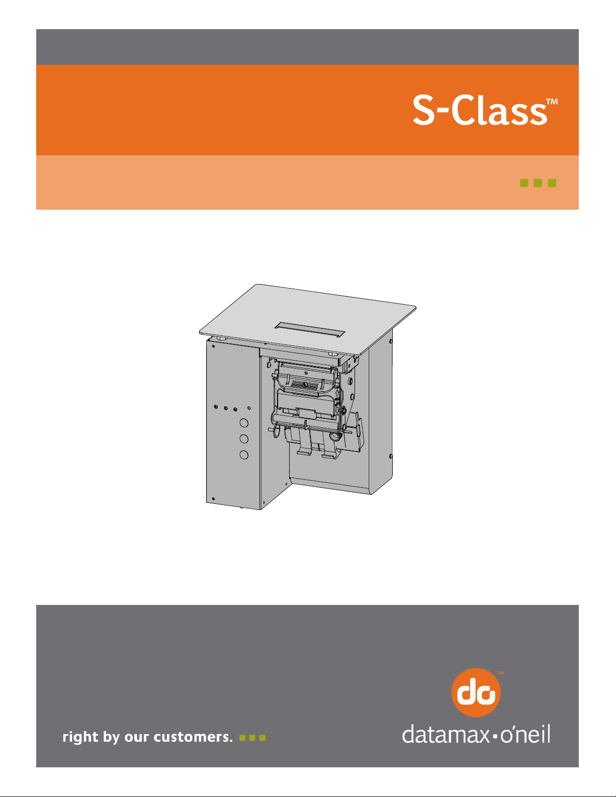
Contents of this Cutter Kit
This kit contains the following items:
1
2
Cutter Assembly
3
Cutter Circuit Card Assembly
Front Plate Assembly
Cutter Input Guide
Screw (3)
4
Screw, with star washer (2)
Washer
5
6
7
Cutter Cable (Non-ROHS)
Cutter Cable (ROHS)
8
9
Tools Required
You will need a Phillips screwdriver and an 8 mm Nut Driver to install this option.
Step A: Preparing the Printer
1. Turn ‘OFF’ the power switch and unplug the AC power cord.
2. Disconnect the interface cable(s).
3. Remove any installed ticket stock and lock the printhead.
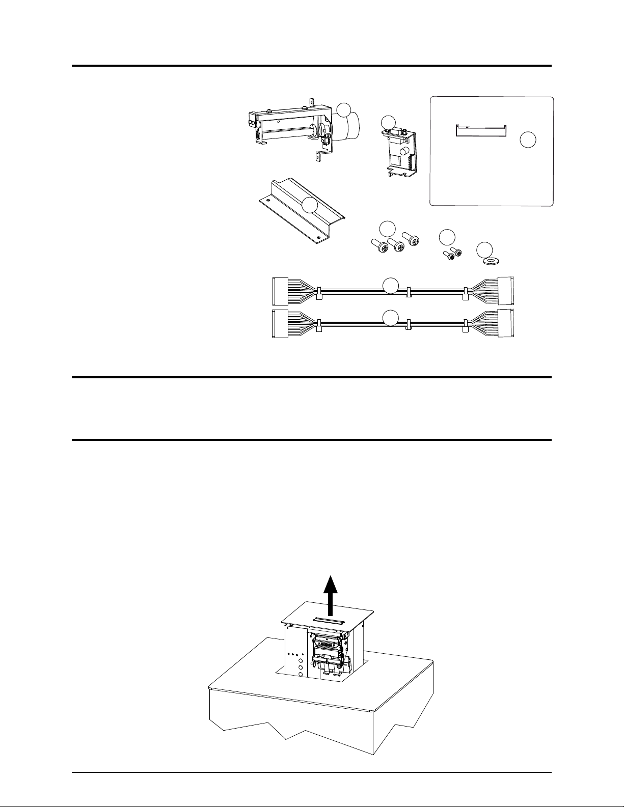
4. Carefully raise the printer from the bottom, guiding it out of the enclosure. Place the printer on a firm,
stable work surface.
1
Page 4
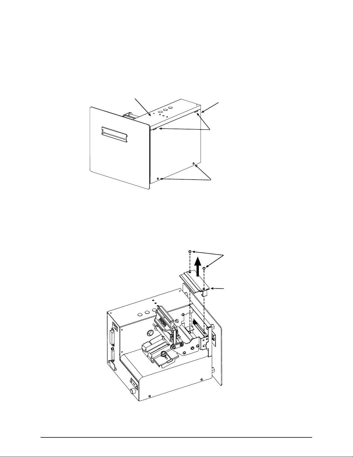
5. Remove the two Screws that secure the Electronics Cover to the printer.
6. Grasp the Electronics Cover from bottom and, while pulling down slightly to free the Catches,
remove the cover.
Front Panel
Electronics Cover
Catches
Screws
7. Unlock and raise the printhead. Remove the two Screws that secure the Tear Input Guide and then
remove the guide.
Screws
Tear Input
Guide
2
Page 5
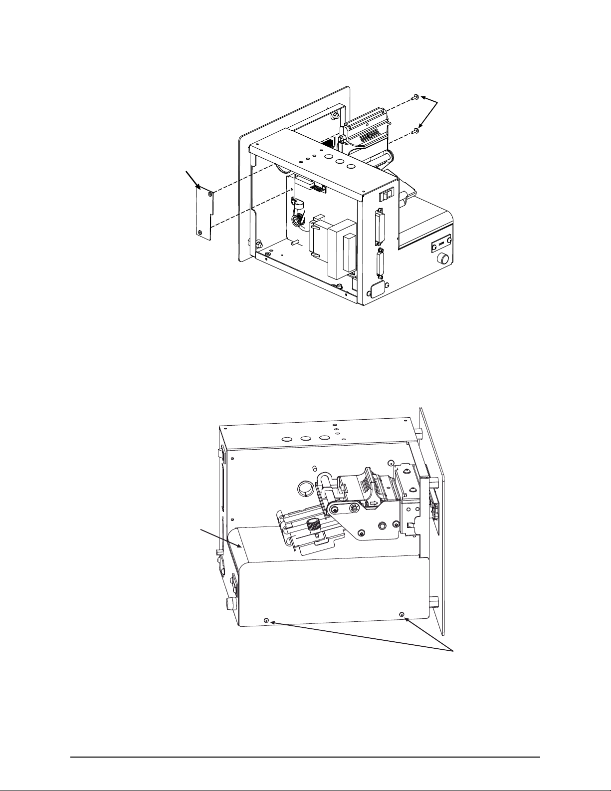
8. Remove the two Screws that secure the Cover Plate and then remove the plate.
Screws
Cover Plate
9. Remove the two Screws that secure the Power Supply Cover. Then remove the cover by sliding it
slightly backward and off the printer.
Power Supply
Cover
Screws
3
Page 6

10. Remove the four Nuts that secure the Front Plate Assembly to the printer and then remove the
assembly. Proceed to Step B of this procedure.
Nuts
(four total)
Front Plate
Assembly
Step B: Installing the Cutter Assembly
1. Insert the Standoffs on the Front Plate Assembly (Item 3) into the printer, and secure the assembly
using the four Nuts removed in Step A-10, above.
Nuts
(four total)
Front Plate
Assembly
Standoffs
4
Page 7

2. Replace the Power Supply Cover by inserting the Tabs into the Slots in the frame, and then secure the
cover using the two previously removed Screws.
Slots
Tabs
Power Supply
Cover
Screws
3. Install the Cutter Input Guide (Item 4) and secure it using the two Screws removed in Step A-7,
above.
Screws
Cutter Input
Guide
5
Page 8

4. Carefully slide the Cutter Assembly (Item 1) into the printer. Ensure that the Guide Pins on the
assembly fit into the Locator Holes in the printer, and then secure the Cutter Assembly in place using
the two Mounting Screws (Item 5).
Guide
Pins
Locator
Holes
Mounting Screws
5. Remove the Screw that secures the Strain Relief to the chassis. (It is not necessary to remove the
Strain Relief or reroute any cabling).
Cutter Assembly
Main CCA
Baseplate
Screw
&
Strain Relief
6
Page 9

6. Install the Cutter CCA (Item 2) into the printer by placing the Tab into the Locator Hole in the
Baseplate.
Cutter CCA
Locator Hole
Tab
7. Insert the Screw (Item 6) into the Washer (Item 7), and then securely fasten the Cutter CCA to the
Baseplate using the Screw and Washer.
Baseplate
Cutter CCA
Screw
Washer
Baseplate
7
Page 10

8. Connect P1 of the Cutter Assembly to J2 of the Cutter CCA, and then secure the connection using
two Screws (Item 6).
There are two cutter cables included with this kit:
Non-ROHS printers: Use Item 8 (32-2430-01)
ROHS printers: Use Item 9 (32-2628-01)
The serial label on the rear of the printer will state if the printer is ROHS compliant.
Connect the Cutter Cable from J1 of the Cutter CCA to J1 of the Main CCA.
J1, Main CCA
P1, Cutter Assembly
Screws
J2, Cutter CCA
J1, Cutter CCA
Cutter Cable
9. Place the Strain Relief around the Cutter Cable, and then secure the Strain Relief to the printer using
the previously removed Screw.
Screw
Strain Relief
Cutter Cable
8
Page 11

10. Replace the electronics cover and secure it using the two previously removed screws. Proceed to Step
C, below.
Step C: Adjusting the Front Plate Brushes
For proper ticket stacking following the cut operation, the Brushes within the Front Plate Assembly must
be adjusted, as follows:
11. Ensure that the Brushes in the Front Plate Assembly are at the widest setting (if necessary , slightly
loosen the Screws and reposition the Brushes; see the drawing below).
12. Manually load ticket stock through the printer and adjust the Media Guides to fit the ticket stock
being used (see the Operator’s Manual for details). Ensure the ticket stock is NOT skewed as it exits
the Ticket Door on the Front Plate Assembly.
Note: If unable to pass ticket stock through the cutter mechanism, the blade may be in the “down” position.
To cycle the blade position, plug the AC power cord into the printer, turn on the power switch, and
allow the printer to initialize (about 30 seconds). Then turn off and unplug the printer.
13. With the Screws on the Front Plate Assembly slightly loosened, move each of the Brushes so that the
Ticket Edges are approximately 1/16 inch (1.5 mm) from the Brush Backing.
Note: Do not over-adjust the Brushes because ticket binding or jamming can occur.
Screws
Ticket Stock
Brush
Ticket Door
(shown as dotted lines)
Front Plate
Assembly
Brushes
Approximately
1/16 inch
(1.5 mm)
Brush
Backing
Ticket Edge
14. Tighten the Screws. Remove the Ticket Stock from the printer.
15. Ensure that the printhead locked down, and then gently lower the printer into its enclosure.
16. Reconnect the interface cable(s). Plug in the AC power cord and turn ‘On’ the power switch. This
completes the installation procedure. Upon power-up, the printer will automatically sense the
presence of the Cutter, and then will cycle the Cutter 1 or 2 times. Load ticket stock. Using your
software program, enable the cut function to begin using the Cutter. Test the stacking function by
printing several test tickets. If the tickets are not stacked, or if they are binding, readjust the brushes,
beginning at Step 11, above.
9
Page 12

Cutter Maintenance
Cutter maintenance is recommended after every 5,000 − 10,000 cuts, an interval that varies depending
upon the type of ticket stock being used. The need for cleaning may also be indicated when the cut
operation becomes slow or labored. To clean the cutter, proceed as follows:
CAUTION
For your safety and to avoid damaging the equipment, follow these precautions:
(1) Always turn ‘Off’ and unplug the printer before servicing the cutter;
(2) Never use a metal object on the blade; and,
(3) Keep fingers and other body parts away from the blade.
1. Turn ‘OFF’ the power switch and unplug the AC power cord. Disconnect the interface cable(s).
2. Remove any installed ticket stock and lock the printhead. Carefully raise the printer from the bottom,
guiding it out of the enclosure, and then place the printer on a firm, stable work surface.
3. Remove the two Screws that secure the Electronics Cover to the printer. Grasp the Electronics Cover
from bottom and, while pulling down slightly to free the Catches, remove the cover (see Step A-6,
above, for an illustration).
4. Remove the two screws that secure P1 to the Cutter CCA, and then remove P1 from the Cutter CCA.
P1
Screws
Cutter CCA
10
Page 13

5. Unlock and raise the printhead. While supporting the Cutter Assembly, remove the two Mounting
Screws, and then carefully slide the Cutter Assembly out of the printer.
Cutter
Assembly
Mounting
Screws
6. Using a soft brush or compressed air, remove all debris from the printer and Ticket Door area.
7. Using a soft brush or compressed air, remove all debris from the Cutter Assembly. Then, using a
cotton swab dampened with isopropyl alcohol, clean the Cutter Blade surfaces until all build-up is
removed.
8. Carefully slide the Cutter Assembly into the printer. Ensure that the Guide Pins on the assembly fit
into the Locator Holes in the printer, and then secure the cutter in place using the two Mounting
Screws.
Guide
Pins
Locator
Holes
Mounting Screws
11
Cutter Assembly
Page 14

9. Reconnect P1 to the Cutter CCA and secure it with the two previously removed screws.
Screws
Cutter CCA
P1
10. Replace the electronics cover and secure with the two previously removed screws.
11. Lower and lock the printhead assembly then gently lower the printer into its enclosure.
12. Reconnect the interface cable(s). Plug in the AC power cord and turn ‘On’ the power switch. This
completes the cleaning procedure. Reload ticket stock.
12
Page 15

Cutting Requirements
Table 1, below, lists the media requirements for use in the cutter mechanism. For a complete listing of
these requirements, see the Operator’s Manual.
Description
Inches Millimeters Inches Millimeters
Ticket Width 2.0 51 3.25 82
Ticket Weight Maximum 150 g/m2 (see note below)
The values in the following tables are only provided as a guide and should not be used as specifications
since variances within the same basis weight can occur due to the characteristics of the stock. In addition,
similar weight stocks can vary between manufacturers.
Note: The cutter may able to cut heavier ticket stock than indicated, but it is recommended that cutting
performance be verified by testing the cutter with the intended stock.
Table 2 shows the approximate media thickness in mils (thousands of an inch) relative to the metric
weight for that media.
Table 3 shows the different basis weights for the differing media types, which are “equivalent” in
weight when compared to the metric weight.
Minimum Maximum
Table 1
Metric Weight to Thickness in Mils Metric Weight to Equivalent Weight in Lbs
Metric
Weight
(g/m2)
50 2.7 2.8 2.1 2.0 1.8 60.0 16.0 22.0 37.0
60 3.2 3.4 2.5 2.4 2.2 66.6 18.0 24.0 41.0
70 3.7 3.9 2.9 2.8 2.6 74.0 20.0 28.0 45.0
80 4.3 4.5 3.3 3.2 2.9 88.8 24.0 33.0 55.0
90 4.8 5.0 3.7 3.6 3.3 103.6 28.0 39.0 64.0
100 5.3 5.6 4.2 4.0 3.7 118.4 31.0 44.0 73.0
110 5.9 6.2 4.6 4.4 4.0 131.7 35.0 48.0 82.0
120 6.4 6.7 5.0 4.8 4.4 135.5 36.0 50.0 83.0
130 6.9 7.3 5.4 5.2 4.8 148.0 39.0 54.0 91.0
140 7.5 7.9 5.8 5.7 5.1 150.5 40.0 56.0 93.0
150 8.0 8.4 6.2 6.1 5.5 161.8 43.0 60.0 100.0
160 8.5 9.0 6.6 6.5 5.9 165.6 44.0 61.0 102.0
170 9.1 9.5 7.1 6.9 6.2 175.8 47.0 65.0 108.0
180 9.6 10.1 7.5 7.3 6.6
Copy
Paper
(mils)
Business
Card Stock
(mils)
Table 2
Ticket
Stock
(mils)
Label w/
Liner
Stock
(mils)
Linerless
label stock
(mils)
Metric
Weight
(g/m2)
199.4 53.0 74.0 122.0
Basis
Weight
(Copy
Paper)
Table 3
Basis
Weight
(Card
Stock)
Basis
Weight
(Tag stock)
13
Page 16

 Loading...