

Page 1

Operator’s Manual
Page 2

Page 3

Copyright Information
CG Triumvirate is a trademark of Agfa Corporation.
Copyright Information
In no event shall Datamax-O’Neil be liable to the purchaser for any indirect,
special or consequential damages or lost profits arising out of or relating to
Datamax-O’Neil’s products, or the performance or a breach thereof, even if
Datamax-O’Neil has been advised of the possibility thereof. Datamax-O’Neil’s
liability, if any, to the purchaser or to the customer of the purchaser hereun der
shall in no event exceed the total amounts paid to Datama x-O’Neil hereunder by
the purchaser for a defective product.
In no event shall Datamax-O’Neil be liable to the purchaser for any damages
resulting from or related to any failure or delay of Datamax-O’Neil in the delivery
or installation of the computer hardware, supplies or software or in the
performance of any services.
Some states do not permit the exclusion of incidental or consequential damages,
and in those states the foregoing limitations may not apply. The warranties here
give you specific legal rights, and you may have other legal rights which vary
from state to state.
Firmware (Software) Agreement
The enclosed Firmware (Software) resident in the EPROM’s is owned by
Licensor or its suppliers and is licensed for used only on a single printer in the
user’s Trade or Business. The User agrees not to, and not to authorize or
permit any other person or party to, duplicate or copy the EPROM’s or the
information contained in the EPROM’s. The firmware (Software) is protected
by applicable copyright laws and Licensor retains all rights not expressly granted .
In no event will Licensor or its suppliers be liable for any damages or loss,
including direct, incidental, economic, special, or consequential damages, arising
out of the use or inability to use the Firmware (Software).
Information in this document is subject to change without notice and does not
represent a commitment on the part of Datamax-O’Neil Corporation. No part of
this manual may be reproduced or transmitted i n any form or by any means, for
any purpose other than the purchaser's personal use, without the expressed
written permission of Datamax-O’Neil Corporation.
All rights reserved
Copyright © 2012, Datamax-O’Neil
Part Number 88-2337-01, Revision D
Page 4

Agency Compliance and Approvals
C US
Listed
FCC:
Note: This equipment has been tested and found to comply with the limits for a Class A
digital device, pursuant to Part 15 of the FCC Rules. These limits are designed to
provide reasonable protection against harmful interference when the equipment is
operated in a commercial environment. This equipment generates, uses, and can
radiate radio frequency energy, and if not installed and used in accordance with
the instructions in this manual, it may cause harmful interference to radio
communications. Operation of this equipment in a residential area is likely to
cause harmful interference in which case the user will be required to correct the
interference at his own expense.
UL60950-1: 2nd Edition
CSA C22.2 No. 60950-1-07 2nd Edition
Gost-R
The manufacturer declares under sole responsibility that this product conforms
to the following standards or other normative documents:
EMC: EN 55022 (2006, A1:2007) Class B
EN 55024 (1998, A1:2001, A2:2003)
Safety: This product complies with the requirements of IEC 60950-1 2nd
ROHS: 2002/95/EC
LVD: 2006/95/EC
This device complies with FCC CFR 47 Part 15 Class A.
Edition, 2005-12
Page 5

Important Safety Instructions:
This printer has been carefully designed to give many years of safe and
reliable performance; however, as with all types of electronic equipment,
there are some basic precautions that should taken to avoid personal
injury or damage to the printer:
Carefully read the installation and operating instructions provided
with this printer.
Read and follow all warning instruction labels on the printer.
Place ST Models on a flat, firm surface; mount SV Models in rigid
enclosure.
To protect the printer from overheating, make sure no openings on
the printer are blocked.
Do not place the printer on or near a heat source.
Do not use the printer near water and never spill liquid into it.
Ensure that the power source meets the ratings listed on the printer;
if uncertain, check with your dealer, electrician, or utility company.
Do not place the power cord where it may be walked on. Should the
power cord becomes damaged or frayed, replace it immediately.
Only qualified, trained service technicians should attempt to repair
this printer.
Page 6

Page 7

Contents
Overview ..................................................................................................1
1.0 About the Printer .............................................................................1
1.0.1 Standard Features ..........................................................2
1.0.2 Optional Features............................................................3
Getting Started ........................................................................................5
2.0 Unpacking........................................................................................5
2.0.1 Inspection .....................................................................6
2.0.2 Additional Requirements.................................................6
Setting-Up the Printer.............................................................................7
3.0 Power Connection...........................................................................7
3.1 Interfacing........................................................................................8
3.1.1 Automatic Parser Mode Detection..................................9
3.2 Loading Ticket Stock .....................................................................10
3.2.1 ST Models ...................................................................10
3.2.2 SV Models ...................................................................16
3.3 Using the Front Panel....................................................................18
3.4 Resident Formats..........................................................................22
3.4.1 Configuration Ticket......................................................22
3.4.2 Test Pattern Ticket........................................................23
3.4.3 Internal Test Ticket........................................................24
3.5 Resetting the Printer......................................................................25
3.6.1 Warm Reset..................................................................25
3.6.2 Factory Default Reset ...................................................25
3.6 Keypad Lockout.............................................................................26
Adjustments and Maintenance............................................................27
4.0 Media Sensor Adjustment.............................................................27
4.0.1 ST Model Media Sensor Adjustment ............................28
4.0.2 SV Model Media Sensor Adjustment............................31
i
Page 8

4.1 Stock ID Selections .......................................................................33
4.2 Start of Print & Cut/Tear Adjustment.............................................35
4.3 Operational Database Modification...............................................36
4.3.1 Database Modification Example ...................................39
4.4 Maintenance..................................................................................40
4.4.1 Printhead Cleaning........................................................41
4.4.2 Platen Roller Cleaning ..................................................43
4.4.3 Media Sensor Cleaning.................................................44
4.4.4 Ticket Detect Sensor Cleaning .....................................46
4.4.5 Interior Cleaning............................................................47
4.4.6 Exterior Cleaning...........................................................48
4.4.7 Downloading Firmware and Fonts................................48
Troubleshooting....................................................................................51
5.0 Help Guide.....................................................................................51
5.1 Hex Dump Mode............................................................................55
Specifications........................................................................................57
6.0 Specifications ................................................................................57
6.1 Approved Ticket Stocks.................................................................63
Appendix A ............................................................................................65
ASCII Control Code Chart.......................................................................65
Appendix B ............................................................................................67
Available Fonts and Barcodes ................................................................67
Appendix C ............................................................................................77
Cable Listings ......................................................................................77
Appendix D ............................................................................................79
SV Model Mounting Dimensions.............................................................79
ii
Page 9

Overview
1.0 About the Printer
ST (Table) Model
SV (Vertical) Model
The S-Class printer family, hereafter referred to by model name, blends
rugged design, state-of-the-art electronics, and user-friendly features to
redefine ticketing hardware.
To process complicated formats quickly, the printer is equipped with a
32-bit microprocessor and four megabytes of memory. Auto-detecting
communication ports ensure that interfacing to the host system is a
simple task, while versatile front panel functions will speed you through
setups.
This manual provides all the information necessary for the daily
operation of the printer. To begin printing tickets, refer to the instructions
included with the software package you have chosen. If you wish to
write a custom program, visit our website at www.datamax-oneil.com for
a copy of the DPL Programmer’s Manual (part number 88-2051-01) and
the DTPL Programmer’s Manual (part number 88-2246-01).
S-Class 1
Page 10

1.0.1 Standard Features
This printer comes equipped with many standard features:
Communication Interfaces
USB interface
DB-9 RS-232 serial interface
IEEE 1284 Centronics
Memory
2 MB FLASH Memory (256K available to user, designated as Module B)
4 MB DRAM Memory
Printing
Direct Thermal
On-demand and batch modes
Automatic ticket loading and positioning
Integrated tear bar
Multiple programming language support
Lockable cover (ST Models only)
Interior ticket platform (ST Models only)
Real-Time Clock
A clock and counter circuit to keep the current time, date, and
amount of inches printed for jobs requiring a time/date stamp as part
of their format.
Scaleable Fonts
Downloadable typeface varieties in point sizes ranging from 4 to
999.
parallel interface
2 S-Class
Page 11

1.0.2 Optional Features
Many optional features are available for this printer:
Cutter and Tray (ST Models only)
This device automatically cuts ticket stock. Stock thickness can range
from .0025 inch (.06 mm) up to .008 inch (.2 mm). A tray, capable of
stacking a minimum of 100, 3.5-inch (88.9 mm) wide tickets, collects the
cut tickets. Order this feature when placing your printer order.
External Ethernet Connectivity (uses printer’s parallel port)
A print server (the DMX100) that is an external Network Interface
Controller (NIC) to provide Ethernet
Print Side Media Sensor (ST Models only)
This option allows the printer to sense TOF marks that are present on the
same side of the media in which printing will occur.
Roll Hanger (ST Models only)
This mounting option allows the printer to use rolled ticket stock with a
maximum 7-inch outer diameter (177.8 mm) on 2-inch (50.8 mm)
diameter core. Order part number 12-2978-01.
connectivity.
S-Class 3
Page 12

4 S-Class
Page 13

Getting Started
2.0 Unpacking
Inspect the shipping container(s) for damage; if evident, notify the
shipping carrier to report the nature and extent of the damage before
proceeding.
The printer is carefully packaged to avoid any damage during transit. In
order to operate the printer, you will need to remove the packaging
materials placed there for shipment. Complete the following steps prior
to connecting power or attempting to load ticket stock.
Carefully open the shipping container, remove the printer, and place it on
a level, stable surface.
Remove the printer from the plastic shipping bag.
Carefully remove the tape that extends
CAUTION
Do not rest SV models “end-down” on any surface. Damage
to the printer’s connectors may occur.
over the Printhead Latch.
(On SV Models also remove the tape
that covers the interface connectors.)
Note: Save all packaging in the event that shipment is ever required.
S-Class 5
Page 14

2.0.1 Inspection
After inspecting the printer, check the remaining contents of the box. In
addition to this manual, the following items should be included:
Ticket Printer
Power cord
Keys (ST Models only)
Accessories CD-ROM
Special or additionally
purchased items.
Important Notice:
2.0.2 Additional Requirements
In addition to the above-mentioned items, the following items are
necessary for ticket printing.
A USB, serial, or parallel interface cable
Applicable ticket stock
Applicable software
For advice on which stock and software is best suited for your needs,
contact your customer service representative.
6 S-Class
Page 15

Setting-Up the Printer
This section details the connections, loading methods, and resident ticket
formats of the printer.
3.0 Power Connection
Note: Before connecting the AC Power Cord or interface cables to the
printer, ensure the Power On/Off Switch is in the ‘Off’ position.
Place the printer on a firm, level surface.
Ensure that the Power Switch on the Printer is in the ‘Off’ position.
Connect the AC Power Cord to the receptacle on the back of the Printer,
and then plug the AC Power Cord into a properly grounded outlet. (The
power supply automatically detects and then adjusts to the applied line
voltage; see Section 6.0 for the acceptable voltage ranges.)
S-Class 7
Page 16

3.1 Interfacing
The printer can be connected to the host via the parallel, USB, or serial, The
printer will automatically connect to the first port that delivers valid data. Once
established, the printer’s power must be cycled ‘Off’ and ‘On’ to change an
interface connection.
Serial Port
USB Port
Serial Port
USB Port
Parallel Port
Power On/Off Switch
AC Power Connector
The Parallel Connection needs a Centronics
Parallel Port
AC Power Connector
Power On/Off Switch
IEEE 1284 cable with a 36pin male connector for unidirectional (forward channel) communications,
or an IEEE 1284 Compliant cable for bi-directional communications
(forward and reverse channels). Also, fo r bi - direct i o nal com m uni cat i ons
your host must have supporting software. See Section 5 for more
information.
The USB Connection needs a USB cable and is supported in Windows
and greater operating systems. Depending upon the operating system of
your host computer, installation requirements may differ slightly.
The Serial Connection needs a serial interface cable with specific pin-
outs for proper communications (part numbers and pin-outs are given,
below; contact your reseller to order). The interface supports RS-232C
communications via a DB-9 connector. Serial port settings are menuselectable and must match your host’s serial port settings; see Section 4.
95
Part # 32-2300-01 Part # 32-2301-01
8 S-Class
Page 17

3.1.1 Automatic Parser Mode Detection
From the factory, the printer will automatically interpret the data
received from the host to set the Parser Mode.
Note: When set to ‘Auto,’ the printer assumes its parser mode according to
the first character received. If the first character is a < (ASCII control
character 3C, as transmitted by most ticketing software packages),
the printer will assume the desired DTPL parser mode. However, in
certain cases (for example, if a font download is executed following
power-up), a received character may cause an unexpected parser
If you want to force the parser mode, see Section 4.3.
More information on identifying the parser m ode setting is a vaila ble in
mode which can falsely appear to be a communications problem.
Section 5, under ‘no communications / not printing via software.’ If
you have any questions or are unab le to establish communications,
contact Datamax-O’Neil Technical Support for help.
S-Class 9
Page 18

3.2 Loading Ticket Stock
The procedure to load the printer differs depending upon the model,
options, and stock type being used. These differences are detailed below.
3.2.1 ST Models
Note: If your printer is equipp ed wit h the Roll Han ger o ption but you want to
use an internal fan-fold ticket source instead, the Roll Hanger must
be removed. Remove the Roll Hanger by turning it counter-clockwise
to unscrew it from the centerplate of the printer.
To load fanfold ticket stock into a table-top printer proceed as follows:
Plug in and turn ‘On’ the printer.
Insert the Key into the lock and turn it, as shown, to unlock the
Access Cover.
Raise the Access Cover (or, for convenience, the cover may be
removed by sliding it forward and then raising it up and off the
hinges).
Perform this step according to the printer’s Media Sensor option and
the type of ticket stock being used:
10 S-Class
Page 19

“Standard Media Sensor” using Fan-Fold Stock –
With the ticket TOF Marks facing ‘down’ (away from you),
place the ticket stock in the bottom of the printer. (If using an
external supply, route the ticket stock into the printer through the
Rear or Bottom Slots.)
Ensure that the Printhead Latch is in the ‘Locked’ position.
Media
Guides
Rear Slot
Unlocked
Locked
Bottom Slot
Thumbscrew
Printhead Latch
Ticket Stock
S-Class 11
Page 20

“Print Side Media Sensor” using Fan-Fold Stock –
With the ticket TOF Marks facing ‘up’ (toward you), place the
stock in the bottom of the printer. (If using an external supply,
route the ticket stock into the printer through the Rear or Bottom
Slots.)
Ensure that the Printhead Latch is in the ‘Locked’ position.
Unlocked
Media
Guides
Rear Slot
Locked
Bottom Slot
Thumbscrew
Printhead Latch
Ticket Stock
12 S-Class
Page 21

“Standard Media Sensor” using Roll Stock –
Mount the roll of ticket stock on the Roll Hanger so that it
unwinds in the direction shown by the arrow in the drawing
below. (The TOF Marks must be wound inward on the roll; see
Section 6 for ticket stock specifications).
Ensure that the Printhead Latch is in the ‘Locked’ position.
Roll Hanger
Unlocked
Locked
S-Class 13
Page 22

“Print Side Media Sensor” using Roll Stock –
Mount the roll of ticket stock on the Roll Hanger so that it
unwinds in the direction shown by the arrow in the drawing
below. (The TOF Marks must be wound outward on the roll; see
Section 6 for ticket stock specifications).
Ensure that the Printhead Latch is in the ‘Locked’ position.
Roll Hanger
Unlocked
Locked
Loosen the Thumbscrew and adjust the Media Guides to fit the width
of the ticket stock.
The guides should be positioned so that there is no side-to-side ticket
movement (too loose), but not so close as to cause friction or bowing
of the ticket (too tight); see the illustration below for examples.
Once properly positioned, tighten the Thumbscrew to secure the
Media Guides in place.
14 S-Class
Page 23

Thumbscrew
Media Guides
(Too Loose)
Thumbscrew
Media Guides
(Too Tight)
Slide the ticket stock farther into the Media Guides until it is grabbed
by the loading mechanism, and then allow the printer to complete the
positioning process. Close the Access Cover.
Note: If automatic loading doesn’t occur, try the following:
1) Ensure that the Printhead Latch is locked.
2) Press the PAUSE button (the On-Line Indicator will go ‘Off’) and
then repeatedly press the F2 button while gently pushing the
3) Press the PAUSE button (to return to the on-line mode).
If the ticket was not fed to a proper position, the Media Sensor may need
adjustment; see Section 4 for details.
stock forward until the printer grabs the ticket.
S-Class 15
Page 24

3.2.2 SV Models
Plug in and turn ‘On’ the printer.
Bring the stock up to the Media Guides (the TOF Marks on the
tickets should be facing away from the Printhead Latch; see Section
4). Ensure that the Printhead Latch is locked.
Locked
Unlocked
Front Panel
Printhead Latch
Thumbscrew
Media Guides
Ticket St ock
Loosen the Thumbscrew and adjust the Media Guides to fit the width
of the ticket stock as described in Step 5 of Section 3.2.1.
Slide the ticket stock through the Media Guides. The motor will
start; continue feeding the tickets. The printer will grab the leading
edge of the stock and complete the positioning process. If this
process fails, see the note on the next page.
16 S-Class
Page 25

Note: If automatic loading doesn’t occur, try the following:
1) Ensure that the Printhead Latch is locked.
2) Press the PAUSE button (the On-Line Indicator will go ‘Off’) and
then repeatedly press the F2 button while gently pushing the
3) Press the PAUSE button (to return to the on-line mode).
If the ticket was not fed to a proper position, the Media Sensor may need
adjustment; see Section 4 for details.
stock forward until the printer grabs the ticket.
S-Class 17
Page 26

3.3 Using the Front Panel
The Front Panel is comprised of a ticket exit, darkness control, three
indicator lights, and three dual-purpose buttons.
ST Models
SV Models
18 S-Class
Page 27

Ticket Exit
The printed tickets are expelled from this opening.
Darkness Control
The Darkness Control adjusts the contrast of the printing on the tickets:
turning the control clockwise darkens the print, while turning the control
counterclockwise lightens it. Darkness can also be controlled through
software.
Indicators
For a brief period after power-up (about 20 seconds), all three indicators
will remain on while the printer performs internal diagnostics.
POWER:
FAULT:
Turning ‘On’ the power switch lights this indicator.
During normal operation, this indicator will flash briefly as
the printer receives data from the host system; however, if a
fault is detected this indicator stays on. A fault can have
several different causes; see Section 5 for details.
ON-LINE:
In the on-line mode, this indicator lights to denote that the
printer is ready to accept data. Pressing the PAUSE button
while tickets remain to print causes the indicator to flash
repeatedly. This indicator remains off in the off-line mode.
S-Class 19
Page 28

Dual-Purpose Buttons
Depending upon the printer’s mode, the buttons function as follows:
On-Line Mode Button Functions
(On-Line, as denoted by the On-Line Indicator being ‘On’)
PAUSE:
Press this to temporarily stop printing (pause mode) or to
enter the off-line mode.
Press this button in pause mode to resume printing from the
point stopped; or, if in off-line mode press to return to the
on-line mode.
FEED:
TEST:
Press this button to advance the ticket stock to the next print
position.
This button is inactive in the on-line mode.
20 S-Class
Page 29

Power-Up and Off-Line Mode Button Functions
(Off-Line, as denoted by the On-Line Indicator being ‘Off’)
F2:
Three functions:
(a) Press momentarily to advance ticket stock, or to
manually load ticket stock.
(b) Press and hold during power-up to print a
Configuration and Test Pattern Ticket, and enter
Character Dump mode.
(c) Press and hold to enter the Operational Database
Modification mode; see Section 4.3 for details.
F3:
Two functions:
(a) Press and hold to enter the Start of Print and
Cut/Tear Adjustments; see Section 4.2 for
details.
(b) Press momentarily to print an Internal Test
Ticket; see Section 3.4.3.
F1 + F3:
Press these simultaneously to perform a Warm Reset
and return to the on-line mode.
F1 + F2:
Press these simultaneously to print a Test Pattern
Ticket; see Section 3.4.2.
F2 + F3:
Press these simultaneously to print a Configuration
Ticket; see Section 3.4.1.
F1 + F2 + F3:
Press and hold these during power-up to reset the
printer to the default settings; see Section 3.5.2.
S-Class 21
Page 30

3.4 Resident Formats
Several formats are stored in memory for useful setup, operational, and
diagnosis information. Load stock that is at least 2 inches (51 mm) wide
to capture all the data and patterns on these resident formats.
3.4.1 Configuration Ticket
The Configuration Ticket provides firmware, memory, and options
information (depending upon the model, equipment, and firmware this
information will vary). To print a Configuration Ticket:
With stock loaded, turn the
printer ‘On’.
Press the PAUSE button to enter
the off-line mode.
Simultaneously press the F2 and
F3 Buttons.
Configuration includes detected
communications (baud rate, the selected
communications port, detected parser
mode, etc.) as well as the speed settings,
Stock ID, and the start of print and
cut/tear positions.
Counter/Memory sections include time
of operation and lengths printed, as well
as the printer’s memory configuration.
(Resettable Values can be useful in
tracking job data; see the DPL
Programmer’s Manual for details.)
Input Values indicates the selected
parser mode and the printer’s internal
sensor values.
22 S-Class
VER: S3210 - 01.00C 04/25/06
BOOT ES-2562-01A
CODE ES-2564-01C
FPGA ES-2563-01A
FONT 83-2565-06A
256K FLASH MODULE B
SYSTEM FLASH SIZE____ 2 MBYTES
SYSTEM RAM CHECKS____ GOOD
SYSTEM RAM SIZE___ 4096 KBYTES
SYSTEM RAM AVAIL__ 3146 KBYTES
CONFIGURATION
DTPL SERIAL PORT DETECTED
9600,8,N
REFL, CUTTER
PRINT SPEED 8.0 IPS
SLEW SPEED 8.0 IPS
BACK SPEED 3.0 IPS
STOCK ID 5
START OF PRINT 4.28 in
CUT/TEAR POSITION 4.26 in
ROW ADJUST 0.00 in
COLUMN ADJUST 0.00 in
VERTICAL ADJUST 11 dpi
PRESENT DELAY
COUNTER INFORMATION
ABSOLUTE VALUES 4-26-2006
LENGTH____ 350 INCHES
TIME______ 4 HOURS
RESETABLE VALUES 6- 5-2002
LENGTH____ 221 INCHES
TIME______ 2 HOURS
MEMORY CONFIGURATION
INTERNAL MODULE A______ 128
SCALABLE FONTS_________ 64
LABEL SIZE 0189:23806 IN
INPUT VALUES
POT_________________ 195
REFL________________ 73
TEMP________________ 67
VOLT________________ 226
STOCK_______________ 40
PARSER MODE_________ DTPL
TOF LOW_____________ 0
TOF DELTA___________ 10
TOF GAIN____________ 6
NO REPRINT__________ NO
Page 31
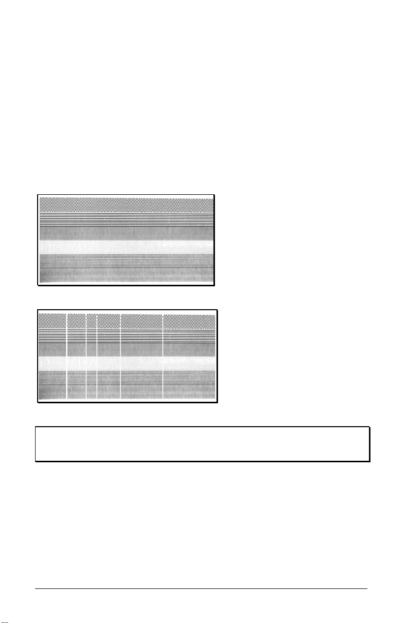
3.4.2 Test Pattern Ticket
The Test Pattern Ticket is a resident format that can be used to determine
general print quality and the condition of the printhead; see the examples
below.
With stock loaded, turn the printer ‘On’.
Press the PAUSE button to put the printer in the off-line mode.
Simultaneously press the F1 and F2 Buttons.
A “Good” Test Pattern Ticket:
Consistent patterns across the
width of the ticket indicate that
the printhead is operating
normally.
A “Faulty” Test Pattern Ticket:
Streaks (vertical lines of missing
print) indicate a dirty or faulty
printhead. See Section 4.4.1 for
cleaning instructions.
Note: The Test Pattern Ticket is generated at the current Darkness and
Speed settings. Adjust these accordingly or use a ticket format
generated from the host for final print quality assessments.
S-Class 23
Page 32

3.4.3 Internal Test Ticket
The Internal Test Ticket is another resident format that is another useful
indicator of print quality. This ticket features various font sizes and
barcodes (the sample below was printed using the ST-3210). To print an
Internal Test Ticket:
With stock loaded, turn the printer ‘On’.
Press the PAUSE button to enter the off-line mode.
Press the F3 button.
24 S-Class
Page 33

3.5 Resetting the Printer
There are two different reset levels possible for the printer:
3.6.1 Warm Reset
To reset the printer and return to the on-line mode: Press the PAUSE
button to go off-line and then press the F1 + F3 Buttons simultaneously.
3.6.2 Factory Default Reset
To return the printer to default database settings (see the table below),
perform the following procedure.
Turn the printer ‘Off’.
Press and hold the PAUSE/F1, FEED/F2 and TEST/F3 Buttons
while turning ‘On’ the printer.
After the Fault Indicator flashes (approximately 20 seconds), release
all three buttons.
For verification, a Configuration Ticket can be printed. The printout will
reflect default settings until new configuration data is sent to the printer.
Default Database Settings
Function ST/SV 3210 Values ST/SV 3306 Values
Memory Configuration: 1
Internal Module
Scalable Fonts
Character Set
(parser mode dependent):
Cutter Auto Detect Auto Detect
Parser Mode:2 DTPL DTPL
Print Speed: 3 8 4
Slew Speed: 3 8 6
Backup Speed: 3 3 3
Stock ID 5 5
Print Width 1.89 inches (48 mm) 1.92 inches (49 mm)
1
Allocations are in 4KB units each and configurable only in DPL Parser Mode.
2
This setting may arrive pre-configured, to change the setting see Section 4.3.1.
3
Values given are in Inches Per Second.
128
64
128
64
See Appendix B See Appendix B
S-Class 25
Page 34

3.6 Keypad Lockout
The Keypad Lockout Function stops the operator's ability to enter the
offline functions in the printer’s menu.
To enable the lockout feature:
Press and hold the PAUSE/F1 and FEED/F2 buttons while turning ‘On’
the printer.
To disable the lockout feature:
Press and hold the FEED/F2 and TEST/F3 buttons while turning ‘On’
the printer.
26 S-Class
Page 35

Adjustments and
Maintenance
This section details important adjustments, settings and periodic
maintenance requirements that will ensure optimum performance.
4.0 Media Sensor Adjustment
The Media Sensor in the printer has two functions:
(1) To sense the presence of ticket stock; and,
(2) To detect the Top of Form (TOF) Mark (a black stri pe, rectangle, or
square, as shown in the illustration below).
The Media Sensor must be adjusted
so that it can “see” the TOF Marks on
the ticket.
When adjusting the sensor make sure
that it is positioned within a Quiet
Zone (and not
over preprinted text or
graphics, since that can cause false
TOF sensing).
Section 6 details other specific
requirements for ticket stocks.
Note: If the ticket stock you are usi ng does not contain TOF Marks, ‘TOF
Sense’ must be set to ‘Continuous.’ (When using this setting, the
length of the ticket is set via software commands.) See Section 4.3.
In this case, the Media Sensor can be adjusted to an y location over
the ticket stock.
Depending upon the printer model and options, the adjustment of the
Media Sensor differs slightly, as detailed in the following subsections.
TOF Mark
(Black Stripe)
Preprinting
may cause false
readings
Always align the
Media Sensor
over a Quiet Zone
S-Class 27
Page 36

4.0.1 ST Model Media Sensor Adjustment
The ST Model can be equipped with either a Standard or a Print Side
Media Sensor. Follow the appropriate procedure for the Media Sensor in
your printer:
Adjusting the Standard Media Sensor –
Turn ‘Off’ the Power Switch. Open the Access Cover.
Loosen the Thumbscrew and adjust the Media Guides to fit the width
of the ticket stock:
The guides should be positioned so that there is no side-to-side ticket
movement (too loose), but not so close as to cause friction or bowing
of the ticket (too tight). (See Step 5 in Section 3.2.1 for an
illustration).
Once properly positioned, tighten the Thumbscrew to secure the
Media Guides in place.
Unlock the Printhead Latch and raise the Printhead Assembly.
Grasp the Slide to move the Media Sensor. Position the sensor so
that it can see the Quiet Zone and the TOF Marks on the ticket stock,
as described in Section 4.0.
28 S-Class
Page 37

Printhead Assembly
Media Sensor
Slide
Ticket Stock
Printhead Latch
Lower the Printhead Assembly and lock the Printhead Latch.
Turn ‘On’ the printer and load ticket stock; see Section 3.2.
Lower and lock the Access Cover.
To verify the alignment, press the FEED button several times – the
stopping point should be the same for each ticket that is output. Note
that if the Fault Indicator illuminates, the sensor needs to be
repositioned (see Section 5 for a complete listing of possible causes).
S-Class 29
Page 38

Adjusting the Print Side Media Sensor –
Turn ‘Off’ the Power Switch. Open the Access Cover.
Loosen the Thumbscrew and adjust the Media Guides to fit the width
of the ticket stock:
The guides should be positioned so that there is no side-to-side ticket
movement (too loose), but not so close as to cause friction or bowing
of the ticket (too tight). (See Step 5 in Section 3.2.1 for an
illustration).
Once properly positioned, tighten the Thumbscrew to secure the
Media Guides in place.
Using a small wrench or nut driver (M3), slightly loosen the Nut that
secures the Media Sensor.
Nut
Print Side Media Sensor
Media Guides
30 S-Class
Page 39

Grasp the Nut to move the Media Sensor. Position the sensor so that
it can see the Quiet Zone and the TOF Marks on the ticket stock, as
described in Section 4.0.
Tighten the Nut securely.
Turn ‘On’ the printer and load ticket stock; see Section 3.2.
To verify the alignment, press the FEED button several times – the
stopping point should be the same for each ticket that is output. Note
that if the Fault Indicator illuminates, the sensor needs to be
repositioned (see Section 5 for a complete listing of possible causes).
4.0.2 SV Model Media Sensor Adjustment
Loosen the Thumbscrew and adjust the Media Guides to fit the width
of the ticket stock:
The guides should be positioned so that there is no side-to-side ticket
movement (too loose), but not so close as to cause friction or bowing
of the ticket (too tight). (See Step 5 in Section 3.2.1 for an
illustration).
Once properly positioned, tighten the Thumbscrew to secure the
Media Guides in place.
Unlock and lower the Printhead Assembly.
Grasp the Media Sensor to move it. Position the Media Sensor so
that is can see the Quiet Zone and the TOF Marks on the ticket stock,
as described in Section 4.0.
S-Class 31
Page 40

Media Sensor
Printhead Assembly
Printhead Latch
Ticket Stock
Raise the Printhead Assembly and lock the Printhead Latch.
Turn ‘On’ the printer and load ticket stock; see Section 3.2.
To verify the alignment, press the FEED button several times – the
stopping point (TOF) should be the same for each ticket output.
32 S-Class
Page 41

4.1 Stock ID Selections
The printer maintains a selection of 10 user modifiable stock setups.
Each setup defaults to a specific print width, start print position and
cut/tear position, where:
The Print Width is the print
distance across the ticket.
The Start of Print Position is the
distance, measured in inches,
from the Media Sensor to
printhead burnline.
The Cut/Tear Position is the
distance, measured in inches,
from the Media Sensor to the
cut (if equipped) or tear position
of the printed ticket.
The Stock ID can be set using the
Operational Database Modification
procedure (see Section 4.3.1). As
defined on the following page,
Stock ID numbers 0 through 8 are
not changeable through host
commands; however, Stock ID 9
will allow host commands to
override the default settings.
If none of the listed Stock ID
selections fit your media, select the
Stock ID that is closest to the
physical dimensions of your stock and then modify the Start of Print and
Cut/Tear positions (see Section 4.2). All changes can be saved to the
Stock ID, allowing commonly used formats to be recalled. To revert to
the default values, reset the printer (see Section 3.6).
S-Class 33
Page 42

The table below lists the default settings, according to the printer model, for each Stock ID number.
Stock ID
Stock ID Default Settings
Print Width
3210 Models 3306 Models
Start of Print
Position
0 3.15" (80.0 mm) 3.20" (81.3 mm) .07" (1.8 mm) .05" (1.3 mm)
1 3.15" (80.0 mm) 3.20" (81.3 mm) 4.28" (108.7 mm) 4.26" (108.2 mm)
2 3.15" (80.0 mm) 3.20" (81.3 mm) 1.67" (42.4 mm) 1.65" (41.9 mm)
3 3.15" (80.0 mm) 3.20" (81.3 mm) .02" (.5 mm) 0
4 1.89" (48.0 mm) 1.81" (46.0 mm) .02" (.5 mm) 0
5 1.89" (48.0 mm) 1.92" (48.8 mm) 4.33" (110.0 mm) 4.30" (109.2 mm)
6 1.89" (48.0 mm) 1.92" (48.8 mm) 1.70" (43.2 mm) 1.67" (42.4 mm)
7 1.89" (48.0 mm) 1.92" (48.8 mm) 1.45" (36.8 mm) 1.42" (36.1 mm)
8 2.20" (55.9 mm) 2.24" (56.9 mm) .07" (1.8 mm) .05" (1.3 mm)
9 3.15" (80.0 mm) 3.20" (81.3 mm) 0 0
*SV Model printers using the Tear Bar must add .07 inch (1.8mm) to these distances for Top Plate clearance of the ticket.
Cut/Tear
Position*
34 S-Class
Page 43
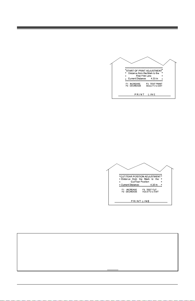
4.2 Start of Print & Cut/Tear Adjustment
If none of the preset Stock ID parameters meet the needs of your
application, then the Start of Print (SOP) and Cut/Tear (C/T)
Adjustments can be used to visually set the required positions. To begin:
If on-line, press the PAUSE button
to place the printer off-line.
Press and hold (approximately 6
seconds) the F3 button until the OnLine Indicator is lit then release.
The SOP setup is first, to adjust:
Press the F1 button to increase the current distance (pressing
and holding will rapidly move the ticket).
Press the F2 button to decrease the current distance (pressing
and holding will rapidly move the ticket).
Press the F3 button to print a ticket showing the new setting.
After completing the SOP adjustment, press and hold (approximately
6 seconds) the F3 button until the On-Line Indicator is lit then
release.
Next, adjust the Cut/Tear position
using the F1, F2 and F3 Buttons
as described above.
After completing the Cut/Tear
adjustment, return the printer to
the off-line mode by pressing and
holding the F3 button until the On-Line Indicator is lit then release.
Press the PAUSE button to return to the on-line mode.
Notes: This procedure must be performed in its entirety, even when no
After completing the adjustments, always confirm the new settings
If using the optional cutter, the cut position on the ticket should
S-Class 35
change is desired for one of the settings.
by printing several test tickets.
occur just behind the perforation, never in front of the perforation.
Page 44

4.3 Operational Database Modification
The operational configuration of the printer, including the Parser Mode
and other parameters, can be changed via the front panel, as follows:
If on-line, press the PAUSE button to place the printer off-line.
Press and hold the F2 button until the On-Line Indicator is lit
(approximately six seconds) then release the button. The printer is
ready for database changes:
Press the F1 button to advance to the next setting of the
current item, print the selection, and present it for
acceptance.
Press the F2 button to accept the presented item and
value for use then print and present the next item, or
press and hold the F2 button (until the On-Line Indicator
is lit) to cause a Warm Reset, apply the new settings, and
place the printer on-line.
Press the F3 button to return to the previous setting for
the current item, print the selection, and present it for
acceptance.
The following pages contain listings of the settings and values that are
accessible and modifiable through this method. Section 4.3.1 contains a
step-by-step example of a parameter modification.
36 S-Class
Page 45

Operational Database: ST/SV-3210 Models
Parameter Description Settings
Stock ID Stock ID number 0-9 (see Section 4.1)
Label (Ticket)
Width
Width of the ticket stock used for
printing.
1.89 inches (48.0 mm)
2.04 inches (51.8 mm)
2.20 inches (55.9 mm)
2.36 inches (59.9 mm)
2.52 inches (64.0 mm)
2.67 inches (67.8 mm)
2.83 inches (71.9 mm)
2.99 inches (75.9 mm)
3.15 inches (80.0 mm)
Parser Mode Sets the emulation of the printer Auto, DTPL, or DPL
Print Speed* Speed during printing 4-10 IPS
Slew Speed* Speed during feeding 4-10 IPS
Backup Speed* Speed during backup 3-5 IPS
Baud Rate Serial communication speed 600, 1200, 2400, 4800, 9600,
19.2K, 38.4K
Word Length Communicated word length 7-bit word (even parity)
8-bit word (no parity)
Cutter Equip Presence of the optional cutter will
Auto or No
be sensed automatically.
Row Adjust** Horizontal adjustment of the point
where printing begins.
Col Adjust** Vertical adjustment of the point
where printing begins.
Vert Adjust** Adjusts the number of formatted
dots in the vertical direction
SOP Adjust Start of Print Position Adjustment
(see Section 4.2)
C/T Adjust Cut/Tear Position Adjustment (see
Section 4.2)
TOF Sense Selects the method for sensing the
-2.55 – 2.55 inches
(-64.8 mm – 64.8 mm)
-2.55 – 2.55 inches
(-64.8 mm – 64.8 mm)
0 – 20
Dots Per Inch
0 – 10.00 inches
(0 – 254 mm)
0 – 10.00 inches
(0 – 254 mm)
Reflective, Continuous
ticket Top Of Form
Present DLY Delay - to stop the printer from
backing up the tickets when
printing multiple tickets.
No Reprint When a fault condition is detected,
0 – 75 sec in 5sec increments
Delays the presentation of the last
ticket printed for the specified time
period.
Yes or No
printing stops and the FAULT light
turns on. After the problem is
corrected, the FEED Key must be
pressed to clear the fault. The label
in process is not reprinted.
*Rates given in Inches Per Second.
** Valid in the DTPL Parser Mode only.
S-Class 37
Page 46

Operational Database: ST/SV-3306 Models
Parameter Description Settings
Stock ID Stock ID number 0-9 (see Section 4.1)
Label Width Width of the ticket stock used for
printing.
1.81 inches (46.0 mm)
1.92 inches (48.8 mm)
2.03 inches (51.6 mm)
2.14 inches (54.4 mm)
2.24 inches (56.9 mm)
2.35 inches (59.7 mm)
2.46 inches (62.5 mm)
2.56 inches (65.0 mm)
2.67 inches (67.8 mm)
2.88 inches (73.2 mm)
2.99 inches (75.9 mm)
3.10 inches (78.7 mm)
3.20 inches (81.3 mm)
Parser Mode Sets the emulation of the printer Auto, DTPL or DPL
Print Speed* Speed during printing 2-6 IPS
Slew Speed* Speed during feeding 2-6 IPS
Backup Speed* Speed during backup 3-5 IPS
Baud Rate Serial communication speed 600, 1200, 2400, 4800, 9600,
19.2K, 38.4K
Word Length Communicated word length 7-bit word (even parity)
8-bit word (no parity)
Cutter Equip Presence of the optional cutter will
Auto, No, Yes
be sensed automatically.
Row Adjust** Horizontal adjustment of the point
where printing begins.
Col Adjust** Vertical adjustment of the point
where printing begins.
Vert Adjust** Adjusts the number of formatted
dots in the vertical direction
SOP Adjust Start of Print Position Adjustment
(see Section 4.2)
C/T Adjust Cut/Tear Position Adjustment (see
Section 4.2)
TOF Sense Selects the method for sensing the
-2.55 – 2.55 inches
(-64.8 mm – 64.8 mm)
-2.55 – 2.55 inches
(-64.8 mm – 64.8 mm)
0 – 20
Dots Per Inch
0 – 10.00 inches
(0 – 254 mm)
0 – 10.00 inches
(0 – 254 mm)
Reflective, Continuous
ticket Top Of Form
Present DLY Delay - to stop the printer from
backing up the tickets when
printing multiple tickets.
No Reprint When a fault condition is detected,
0 – 75 sec in 5sec increments
Delays the presentation of the last
ticket printed for the specified time
period.
Yes or No
printing stops and the FAULT light
turns on. After the problem is
corrected, the FEED Key must be
pressed to clear the fault. The label
in process is not reprinted.
*Rates given in Inches Per Second.
** Valid in the DTPL Parser Mode only.
38 S-Class
Page 47

4.3.1 Database Modification Example
This section details the modification of an Operational Database
parameter. The following example increases the printing speed parameter
from 6 to 8 IPS on the ST-3210; however, using the same basic
procedure, any of the parameters can be changed regardless of the printer
model.
If on-line, press the PAUSE button to place the printer off-line.
Press and hold the F2 button until the On-Line Indicator is lit
(approximately six seconds) then release.
The printer will turn off the
On-Line Indicator and
print:
Press the F2 button three times (allow time for printing following
each button press), to arrive at the Print Speed parameter.
The printer will print:
Press the F1 button two times (again, allow time for printing
following each button press), to arrive at the 8 IPS setting.
The printer will print:
To save the changes and exit the mode, press and hold the F2 button
until the On-Line Indicator is lit (approximately six seconds) then
release.
The parameter changes can be confirmed by printing a Configuration
Ticket; see Section 3.5.1.
STOCK ID = 5
PRINT SPEED = 6 IPS
PARSER MODE = AUTO
TICKET WIDTH = 189 (48 MM)
STOCK ID = 5
PRINT SPEED = 8 IPS
PRINT SPEED = 7 IPS
PRINT SPEED = 6 IPS
PARSER MODE = AUTO
TICKET WIDTH = 189 (48 MM)
STOCK ID = 5
S-Class 39
Page 48

4.4 Maintenance
Routine maintenance will ensure the optimum performance of the printer.
The following table outlines the recommended cleaning intervals, while
the items listed below will help do the job safely and effectively:
Isopropyl alcohol
Cotton swabs Soapy water/mild detergent
A clean, lint-free cloth Compressed air
CAUTION
Printhead A cotton swab dampened with isopropyl alcohol,
Ticket Detect
(ST Models
(optional
equipment)
Area Method Interval
Platen
Roller
Media
Sensor
Sensor
Ticket
Path
Interior
only)
Exterior A soft cloth dampened with a mild detergent to
Cutter
Soft-bristled brush
For your continued safety and to avoid damaging the unit, always
turn ‘Off’ and unplug the printer before servicing.
Isopropyl alcohol is a flammable liquid; always take the proper
precautions when using this solvent.
Recommended Cleaning Schedule
After each
wiped across the printhead until all build-up is
removed. See Section 4.4.1.
A cotton swab dampened with isopropyl alcohol
wiped across the platen roller. Rotate the roller by
hand and repeat to clean entire surface. See
Section 4.4.2.
A brush or compressed air (and isopropyl alcohol,
if necessary) to remove all dust build-up. See
Section 4.4.3.
Compressed air to remove all dust build-up. See
Section 4.4.4.
A brush or compressed air to remove all build-up
along the paper path.
A brush or compressed air to remove all build-up
in the ticket compartment. See Section 4.4.5.
remove all build-up. See Section 4.4.6.
A brush or compressed air to remove all build-up.
roll or box
of tickets.
After each
roll or box
of tickets.
Monthly
or as
needed.
As needed.
As needed.
As needed.
As needed.
As needed.
40 S-Class
Page 49

4.4.1 Printhead Cleaning
Declining print quality (for example, streaking or smudging) is usually
caused by a surface build-up of dirt on the printhead; see Section 3.5.2. If
left unattended, this build-up can lead to permanent printhead damage.
Clean the Printhead as follows:
Turn ‘Off’ and unplug the printer. (ST Models: Raise the access
cover; see Section 3.2.)
Slide the Printhead Latch to the ‘Unlocked’ position and then raise
(or, in the case of SV Models, lower) the Printhead Assembly.
Using a cotton swab dampened
with isopropyl alcohol gently wipe
the Printhead surface, paying close attention to the Burnline,
cleaning until all build-up is removed.
CAUTION
S-Class 41
NEVER use a sharp object to clean the Printhead. Damage can
result.
Page 50

Printhead Assembly
Printhead
Cotton
Swab
Burnline
Surface
Build-up
Allow the Printhead to dry.
Lower (or raise) the Printhead Assembly and slide the Printhead
Latch forward to the ‘Locked’ position.
Plug in and turn ‘On’ the printer. Load ticket stock; see Section 3.2.
(ST Models: Close the access cover.) This completes the procedure.
42 S-Class
Page 51

4.4.2 Platen Roller Cleaning
Print quality can decline if the platen roller becomes contaminated with
paper dust, grit or adhesive. When this build-up is not removed, it can
cause abrasive damage to the printhead. Clean the Platen Roller as
follows:
Turn ‘Off’ and unplug the printer. (ST Models: Raise the access
cover; see Section 3.2.)
Slide the printhead latch to the ‘unlocked’ position and then raise (or,
in the case of SV Models, lower) the printhead assembly; see Section
4.4.1. Remove any ticket stock.
Using a cotton swab or lint-free cloth dampened
alcohol, remove all debris on the Platen Roller. Manually rotate the
roller and repeat until the entire surface has been cleaned.
with isopropyl
CAUTION
S-Class 43
NEVER use a sharp object to clean the Platen Roller. Damage
can result.
Page 52

Allow the Platen Roller to dry.
Lower (or raise) the printhead assembly and slide the printhead latch
into the ‘locked’ position.
Plug in and turn ‘On’ the printer. Load ticket stock; see Section 3.2.
ST Models: Close the access cover. This completes the procedure.
4.4.3 Media Sensor Cleaning
If the Media Sensor becomes blocked with paper particles, TOF
detection may become inconsistent and result in fault conditions. Clean
the sensor as follows:
Turn ‘Off’ and unplug the printer. (ST Models: Raise the access
cover; see Section 3.2.)
Slide the printhead latch to the ‘unlocked’ position and raise (or, in
the case of SV Models, lower) the printhead assembly (see Section
4.4.1).
Remove any ticket stock.
Perform this step according to the printer’s Media Sensor option:
Print Side Media Sensor option –
Using compressed air, direct an air stream under the Print Side
Media Sensor to remove any debris.
Slot
Print Side Media Sensor
Use compressed air here
Media Guide
44 S-Class
Page 53

Standard Media Sensor option –
Using a soft-bristled brush or compressed air, sweep or direct an air
stream into the Media Sensor to remove any debris. (In cases of
extreme build-up, a cotton swab dampened
isopropyl alcohol can be
used to wipe off the sensor; however, if this method is used, allow
the sensor to dry before proceeding.)
Cotton Swab
Printhead Assembly
Media Sensor
Lower the printhead assembly and slide the printhead latch into the
‘locked’ position.
Plug in and turn ‘On’ the printer. Load ticket stock; see Section 3.2.
ST Models: Close the access cover. This completes the procedure.
S-Class 45
Page 54

4.4.4 Ticket Detect Sensor Cleaning
The Ticket Detect Sensor initiates the auto-loading process by signaling
the presence of ticket stock within the Media Guides. If the sensor
becomes blocked with paper particles, ticket feeding problems can occur.
Clean the sensor as follows:
Turn ‘Off’ and unplug the printer. (ST Models: Raise the access
cover; see Section 3.2.)
Slide the printhead latch to the ‘unlocked’ position and raise (or, in
the case of SV Models, lower) the printhead assembly (see Section
4.4.1).
Remove any ticket stock.
Lower (or raise) the printhead assembly and slide the printhead latch
into the ‘locked’ position.
Using compressed air, direct an air stream under the area indicated
by dotted line in the drawing below to clean the sensor.
Ticket Detect Sensor
(located under the Media Guide)
Media Guide
Use compressed air here
Plug in and turn ‘On’ the printer. Load ticket stock; see Section 3.2.
ST Models: Close the access cover. This completes the procedure.
46 S-Class
Page 55

4.4.5 Interior Cleaning
Required for ST Models only
Over time particles of ticket stock accumulate inside the printer. These
particles can stick to the ticket and cause voids in the print. Clean the
interior of the printer as follows:
Turn ‘Off’ and unplug the printer. Raise the access cover; see
Section 3.2.
Slide the printhead latch to the ‘unlocked’ position, raise the
printhead assembly (see Section 4.4.1), and remove the ticket stock.
Using a soft brush or compressed air, r emove all debris from inside
the ticket compartment.
Lower the printhead assembly and slide the printhead latch into the
‘locked’ position.
Plug in and turn ‘On’ the printer. Load ticket stock (see Section 3.2)
and close the access cover. This completes the procedure.
S-Class 47
Page 56

4.4.6 Exterior Cleaning
When necessary, the exterior surface can be cleaned using a general
purpose cleanser and a soft cloth or sponge. Clean printers exterior
covers as follows:
Turn ‘Off’ and unplug the printer.
Gently wipe the exterior surfaces until clean and then allow time to
dry.
Plug in and turn ‘On’ the printer.
CAUTION
NEVER use abrasive cleansers or solvents. NEVER spray
cleansers into the printer or allow over-spray to get on internal
components, such as the printhead. Damage can result.
4.4.7 Downloading Firmware and Fonts
The operating programs and fonts for the printer are stored in Flash memory on
the Main PCB. When program updates and/or new features are added, they can
be downloaded to the printer as follows:
1.
Identify the new version for your model of printer from the DatamaxO’Neil Web site at www.datamax-oneil.com and download it onto your
computer’s hard drive or a floppy disk.
2. Ensure that the printer is connected to the host, (via parallel port only) and
that the power is ‘On.’ Using the DOS copy command enter:
copy filename.dlf lpt1/b
copy filename.zs lpt1/b
Note: Other programs (e.g., hyper-terminal and certain Windows
Driver programs) may also be used to download this file.
3. The ON-LINE light will flash during the download.
(non-display printer firmware is .dlf extension)
(display printer firmware is .zs extension)
48 S-Class
Page 57

4. Following a successful download, the printer will perform a ‘cold
reset.’ The previous printer setup will not be affected unless
substantial firmware data structure changes have occurred. Print a
Database Configuration Label to verify your new firmware version.
Following an unsuccessful download, the FAULT Light will
illuminate then the printer will perform a ‘warm reset’ The original
firmware will remain operational. If the printer fails to reset, toggle the
power ‘Off’ and ‘On.’
Try re-sending the file to the printer. If the failure continues,
check the following possible causes:
An invalid or co rrupted file is being downloaded - Ensure the file
being downloaded is correct and applicable for your printer model.
Possible communications error - Check the cable connection
between the host and printer and ensure that a quality, shielded
cable is used.
Possible Flash memory problem - Call for service.
S-Class 49
Page 58

50 S-Class
Page 59

Troubleshooting
5.0 Help Guide
This section addresses common problems and suggests solutions. While
not all situations can be addressed, many suggestions may prove helpful;
however, if a problem persists or is not covered in this text, contact
Datamax-O’Neil Technical Support or a qualified service technician.
Note: If the Fault Indicator is lit, the FEED button must be pressed after
completing the corrective action to clear the alarm and return the
printer to normal operation.
If experiencing this problem… Try this Corrective Action…
The printer fails to power-up:
All three indicator lights are ‘On’:
The AC power cord may be faulty; try
another cord.
The AC outlet may be faulty; try
moving the printer to another wall
outlet.
The printer is online but is out of stock,
see section 3.2.
The printer has failed to initialize; call
for service.
S-Class 51
Page 60

If experiencing this problem… Try this Corrective Action…
No communications / not
printing via software:
The parser mode may not match the
software (language) being used. Print a
Configuration Label to check the
detected parser mode setting (see
Section 3.4.1) or see Section 5.1 for
more information. See Section 4.3 to
reconfigure the parser mode setting,
depending upon your software progr am,
for DTPL or DPL.
The communication parameters between
the printer and host may not match;
Print a Configuration Label to check the
current port settings (see Section 3.4.1)
See Section 4.3 to reconfigure the
printer to match the host computer’s
settings.
The interface connection may be faulty
or the cable may be incorrect or faulty;
check the connections and see
Appendix C for cable requirements.
Poor print quality / not printing
(including resident formats):
The printhead latch may be unlocked;
lock the latch. See Section 3.2.
The printhead may be dirty; clean per
Section 4.4.1.
The heat setting may be incorrect. Use
the Darkness Control (see Section 3.4),
or adjust the heat setting through the
software program (software will
override the Front Panel setting). In
addition, print speed can also be used to
darken or lighten print.
The type of ticket stock may be
incorrect (i.e., thermal transfer).
52 S-Class
Page 61

If experiencing this problem… Try this Corrective Action…
After printing the ticket, the
Fault Indicator lights:
If cutter equipped, this may indicate a
cutter fault; call for service.
If not cutter equipped:
a) Possible programming problem.
b) Possible mechanical problem – try
pressing the FEED button to clear
the fault: if no response, call for
service. Otherwise, the positioning
of the Media Sensor may need an
adjustment (see Section 4.0).
The printer feeds when no ticket
stock is present or :
The printer feeds approximately
20 inches (51 cm) of ticket stock
then the Fault Indicator lights:
The Ticket Detect Sensor may be
obstructed; clean the sensor per Section
4.4.4.
The position of the Media Sensor may
need adjusting; see Section 4.0.
The Media Sensor may be obstructed;
clean the sensor, see Section 4.4.3.
The TOF Mark on the ticket stock may
not meet specifications; see Section 6.
Ticket stock may be mounted upside
down; reinstall correctly, see Section
3.2.
Tickets sometimes jam and/or
the printing is not square to the
ticket borders:
The printhead may not be latched; see
Section 4.4.1.
The Media Guides may be incorrectly
positioned; see Section 3.2.
If cutter equipped, the cutter may be
malfunctioning; call for service.
S-Class 53
Page 62

If experiencing this problem… Try this Corrective Action…
The printer does not print
formats sent from the host, but
the Fault Indicator remains off:
The parser mode may not match the
software (language) being used. Print a
Configuration Label to check the
detected parser mode setting (see
Section 3.4.1) or see Section 5.1 for
more information. See Section 4.3 to
reconfigure the setting.
The communication parameters between
the printer and host may not match;
reconfigure, see Section 4.3.1.
The interface connection may be faulty
or the cable may be incorrect or faulty;
check the connections and see Appendix
C for cable requirements.
The printer may be in ‘hex dump mode’
(see Section 5.1); cycle the printer
power ‘Off’ and ‘On’.
Erratic print (strange characters
instead of ticket formats are
printed):
The cutter fails to cut, but the
Fault Indicator remains off:
The printer may be in ‘hex dump
mode’; see Section 5.1.
If using the serial interface port, check
the host and printer communications
settings; see Section 3.4.1.
First verify the cutter has been detected by
printing a Configuration Ticket; see
Section 3.5.1. If the cutter has not been
detected, call for service; otherwise,
verify that the cut function has been
selected in the software program.
54 S-Class
Page 63

5.1 Hex Dump Mode
The hex dump mode is a useful tool for diagnosing problems including
communication and programming syntax errors. To enter the hex dump
mode:
With ticket stock loaded, turn ‘Off’ the printer.
Press and hold the FEED button while turning ‘On’ the printer.
Continue to hold the button until tickets feed forward. After a brief
hesitation, Configuration and Test Pattern. Now the printer is in hex
dump mode; until power is cycled ‘Off and On,’ all data reaching the
printer will be output in hex/ASCII code.
The following hex dump examples illustrate the different parser mode
languages that can be interpreted by the printer:
3C in this location denotes
that a DTPL label format
was sent to the printer.
02 in this location denotes
that a DPL label format
was sent to the printer.
To decode this hexadecimal code and its printable ASCII equivalents, the
DPL Programmer’s Manual or the DTPL Programmer’s Manual is an
essential reference. As a final note, many software programs use bit
mapping to construct the ticket, making diagnosis difficult. Contact a
Datamax-O’Neil Technical Support Representative with any questions.
Note: To exit hex dump mode, turn the Power Switch ‘Off’ and ‘On’.
S-Class 55
Page 64

56 S-Class
Page 65

Specifications
6.0 Specifications
Barcodes/Fonts
Barcode Symbologies
(mode dependent):
Font Expansion and
Rotations:
Resident Fonts
(mode dependent):
Optional Fonts:
(See Appendix B for examples)
DPL Parser Mode: Code 39, Interleaved 2 of 5,
Code 128 (subsets A, B, and C), Codabar,
LOGMARS, UPC-A, UPC-E, UPC 2 & 5 digit
addendum's, EAN-8, EAN-13, EAN 2 & 5
digit addendum's, UPC random weight, Code
93, MSI Plessey, Universal Shipping Container
Symbology, Code 128 MOD 43, Postnet,
USS/EAN-128 random weight, Telepen, UPS
MaxiCode modes 2 & 3 (AIM specification,
June 18,1996) and PDF417.
DTPL Parser Mode: Code 39, Code 128
(subsets A, B, and C), Interleaved 2 of 5, UPCA, EAN-8, EAN-13, and Codabar.
All fonts expandable vertically and horizontally
up to 8x; fonts and graphics can be printed in
four directions: 0°, 90°, 180° and 270°.
DPL Parser Mode: Nine alphanumeric fonts
from 0.035"H (0.89mm) to 0.64"H (16mm),
including OCR-A and OCR-B; CG Triumvirate
Bitmap Font - DPL 9 in 4, 5, 6, 8, 10, 12, 14,
18, 24, 30, 36, 48, 72 point size fonts (point
sizes 4 and 5 are available for ST/SV 3306
models only).
DTPL Parser Mode: 13 different typefaces and
sizes.
AGFA Scalable Font Engine supporting
downloads of Intellifont and True Type Font
formats.
S-Class 57
Page 66

Communications
Interface USB, RS-232 (DB-9), and IEEE 1284
Baud Speed
Handshaking
Parity
Stop Bits
Data Bits
Compliant Centronics Parallel
600 to 38,400 bits per second (BPS)
Xon/Xoff, CTS, DTR
Even, Odd, or None
1 or 2
7 or 8
Control (Front) Panel
Buttons: Dual Purpose: Pause/F1; Feed/F2; and Test/F3
Indicators: Power, Fault and On-Line.
Potentiometer: 0-20 darkness settings
Electrical
Grounding: Unit must be connected to a properly
AC Input Voltage
grounded receptacle.
90 – 132 or 180 – 264 VAC @ 47–63 Hz,
auto-ranging.
Environmental
Dust: Non-conducting, non-corrosive
Electromagnetic Radiation: Moderate RF fields can be tolerated
Operating Temperature
Humidity
40 F to 100 F (4 C to 38 C)
10% 95% non-condensing
58 S-Class
Page 67

Mechanical
Depth:
ST-3210 & -3306
SV-3210 & -3306
Height:
ST-3210 & -3306
SV-3210 & -3306
Width:
ST-3210 & -3306
SV-3210 & -3306
Weight:
ST Models –
SV Models –
Top Plate (SV Models only):
Ticket Compartment (ST
Models only):
14 inches (35.6 cm)
7.65 inches (19.4 cm)
10.5 inches (26.7 cm)
10.5 inches (26.7 cm)
8.14 inches (20.7 cm)
8.05 inches (20.4 cm)
22 pounds (10 kg)
18.8 pounds (8.46 kg)
9.71 inches (24.7 cm) W x 8.60 inches (21.8
cm) DP x .09 inch (2.27 mm) THK
Fanfold Ticket Height – 4.5 inches (114.3
mm); Fanfold Ticket Length – 11.375 inches
(289 mm).
Roll Ticket Size (with Roll Hanger option) –
7-inch (178 mm) maximum outer diameter roll
on a 2-inch (51 mm) minimum inner diameter
core.
S-Class 59
Page 68

Print Engine
DRAM Memory: 4 MB
FLASH Memory:
Maximum Fields and
Characters Per Ticket:
Media Sensing:
Printhead Dot Size (nominal):
ST/SV-3210 –
ST/SV-3306 –
Print Length Range:
Print Resolution:
ST/SV-3210 –
ST/SV-3306 –
Print Width, Maximum:
ST/SV-3210 –
ST/SV-3306 –
Print Speed Range:
ST/SV-3210 –
ST/SV-3306 –
Speed, Reverse:
Speed, Slew:
ST/SV-3210 –
ST/SV-3306 –
Printing Type:
2 MB
600 fields with 16,000 characters per ticket
Reflective
.0043 inch X .0052 inch (.108 mm X .132 mm)
.0027 inch X .0043 inch (.069 mm X .110 mm)
1 – 12 inches (25.4mm – 304.8 mm) at default
settings.
203 DPI (8 dots/mm)
300 DPI (11.8 dots/mm)
3.15 inches (80 mm)
3.20 inches (81.2 mm)
4.0 – 10 IPS (102 – 254 mmps)
2.0 – 6 IPS (51 – 152 mmps)
3.0 5.0 IPS (76 127 mmps)
4.0 10.0 IPS (72 254 mmps)
2.0 – 6.0 IPS (51 – 152 mmps)
Direct Thermal
60 S-Class
Page 69

Ticket Stock Requirements
[1]:
Type
Roll Stock
Thickness Range:
1
The ST Model has space restrictions when ticket stock is stored internally, see
‘Mechanical / Ticket Compartment,’ above.
2
The mark must be black carbon-based ink, with a reflectance that is less than 10% at
wavelengths of 950 and 640 nm.
Fan-fold (and roll, if option equipped)
reflective
[1]
(media sensor
dependant):
Print Side Media Sensor –
Standard Media Sensor –
Standard Model –
Cutter-Equipped Model –
TOF Marks wound facing ‘out.’
TOF Marks wound facing ‘in.’
.005-inch minimum to a .010-inch maximum.
.005-inch minimum to a .008-inch maximum.
[2]
or continuous direct thermal stock.
S-Class 61
Page 70

Ticket Stock Requirements (continued)
Dimension
Description
A Ticket Width 2.0 3.25
[3]
Minimum Maximum Layout
B Reflective Mark Width
C Reflective Mark Length
D Distance between Reflective Marks
E Ticket Length
[4]
F Quiet Zone Width
3
Units of measure are given in inches, and all dimensions are referenced in the direction of ticket travel through the printer.
4
The maximum allowable length of the combined ticket and mark measurement cannot exceed 99.99 inches.
5
This is an area free of reflective printing (excluding the reflective marks) that runs the entire length of the ticket.
6
Standard Media Sensor: The center of this mark must fall between .235 and 3.03 inches from the ticket edge, while allowing an adequate Quiet
Zone within that area.
Print Side Media Sensor: The center of the mark must fall between .250 and .750 of an inch from the ticket edge, while allowing an adequate
Quiet Zone within that area.
[6]
.50 3.25
[4]
.125 –
[4]
1.0 –
1.0 –
[5]
.40 3.25
F
C
E
D
B
A
62 S-Class
Page 71

6.1 Approved Ticket Stocks
For optimum print quality, maximum printhead life, and warranty
compliance Datamax-O’Neil recommends the following ticket stocks.
Contact a Datamax-O’Neil Media Representative at (407) 523-5650 with
any questions regarding your specific application.
Manufacturer Material Comment
Ricoh
Ricoh
Kanzaki
120 TLA 1901
150 TLA 190
KT-370
Best quality for high-speed printing,
10 inches per second (IPS), and high
quality applications. Recommended
for use with the ST/SV-3306.
Mid range. Best with print speeds
up to 8 IPS.
Mid range. Best with print speeds
up to 5 IPS.
S-Class 63
Page 72

64 S-Class
Page 73

Appendix A
ASCII Control Code Chart
Char Dec Hex Char Dec Hex Char Dec Hex Char Dec Hex
Ctrl @ NUL 0 00 32 20 @ 64 40 ` 96 60
Ctrl A SOH 1 01 ! 33 21 A 65 41 a 97 61
Ctrl B STX 2 02 “ 34 22 B 66 42 b 98 62
Ctrl C EXT 3 03 # 35 23 C 67 43 c 99 63
Ctrl D EOT 4 04 $ 36 24 D 68 44 d 100 64
Ctrl E ENQ 5 05 % 37 25 E 69 45 e 101 65
Ctrl F ACK 6 06 & 38 26 F 70 46 f 102 66
Ctrl G BEL 7 07 ‘ 39 27 G 71 47 g 103 67
Ctrl H BS 8 08 ( 40 28 H 72 48 h 104 68
Ctrl I HT 9 09 ) 41 29 I 73 49 i 105 69
Ctrl J LF 10 0A * 42 2A J 74 4A j 106 6A
Ctrl K VT 11 0B + 43 2B K 75 4B k 107 6B
Ctrl L FF 12 0C , 44 2C L 76 4C l 108 6C
Ctrl M CR 13 0D - 45 2D M 77 4D m 109 6D
Ctrl N SO 14 0E . 46 2E N 78 4E n 110 6E
Ctrl O SI 15 0F / 47 2F O 79 4F o 111 6F
Ctrl P DLE 16 10 0 48 30 P 80 50 p 112 70
Ctrl Q DC1 17 11 1 49 31 Q 81 51 q 113 71
Ctrl R DC2 18 12 2 50 32 R 82 52 r 114 72
Ctrl S DC3 19 13 3 51 33 S 83 53 s 115 73
Ctrl T DC4 20 14 4 52 34 T 84 54 t 116 74
Ctrl U NAK 21 15 5 53 35 U 85 55 u 117 75
Ctrl V SYN 22 16 6 54 36 V 86 56 v 118 76
Ctrl W ETB 23 17 7 55 37 W 87 57 w 119 77
Ctrl X CAN 24 18 8 56 38 X 88 58 x 120 78
Ctrl Y EM 25 19 9 57 39 Y 89 59 y 121 79
Ctrl Z SUB 26 1A : 58 3A Z 90 5A z 122 7A
Ctrl [ Esc 27 1B ; 59 3B [ 91 5B { 123 7B
Ctrl \ FS 28 1C < 60 3C \ 92 5C | 124 7C
Ctrl ] GS 29 1D = 61 3D ] 93 5D } 125 7D
Ctrl ^ RS 30 1E > 62 3E ^ 94 5E ~ 126 7E
Ctrl _ US 31 1F ? 63 3F _ 95 5F 127 7F
S-Class 65
Page 74

ASCII Control Code Chart (continued)
Char Dec Hex Char Dec Hex Char Dec Hex Char Dec Hex
Ç 128 80 á 160 A0 192 C0 Ó 224 E0
ü 129 81 í 161 A1 193 C1 ß 225 E1
é 130 82 ó 162 A2 194 C2 Ô 226 E2
â 131 83 ú 163 A3 195 C3 Ò 227 E3
ä 132 84 ñ 164 A4 196 C4 õ 228 E4
à 133 85 Ñ 165 A5 197 C5 Õ 229 E5
å 134 86
ç 135 87 ° 167 A7 Ã 199 C7 p 231 E7
ê 136 88 ¿ 168 A8 200 C8 p 232 E8
è 137 89 ® 169 A9 201 C9 Ú 233 E9
è 138 8A 170 AA 202 CA Û 234 EA
ï 139 8B 1/2 171 AB 203 CB Ù 235 EB
î 140 8C 1/4 172 AC 204 CC ´y 236 EC
ì 141 8D ¡ 173 AD 205 CD ´Y 237 ED
Ä 142 8E 174 AE 206 CE 238 EE
Å 143 8F
É 144 90 176 B0 Ò 208 D0 240 F0
Æ 145 91 177 B1 D 209 D1 ± 241 F1
Æ 146 92
ô 147 93
ö 148 94 ´ 180 B4 È 212 D4 244 F4
ò 149 95 Á 181 B5 213 D5 245 F5
û 150 96 Â 182 B6 Í 214 D6 ÷ 246 F6
ù 151 97 À 183 B7 Î 215 D7 ¸ 247 F7
ÿ 152 98 © 184 B8 Ï 216 D8 ° 248 F8
Ö 153 99
Ü 154 9A 186 BA 218 DA · 250 FA
Ø 155 9B » 187 BB 219 DB 251 FB
£ 156 9C 188 BC 220 DC 252 FC
Ø 157 9D ¢ 189 BD 221 DD 253 FD
x 158 9E ¥ 190 BE Ì 222 DE 254 FE
ƒ 159 9F 191 BF 223 DF
166 A6 ã 198 C6 µ 230 E6
a
175 AF 207 CF 239 EF
–
178 B2 Ê 210 D2 242 F2
2
179 B3 Ë 211 D3 3/4 243 F3
3
185 B9 217 D9 ¨ 249 F9
1
255 FF
66 S-Class
Page 75

Appendix B
Available Fonts and Barcodes
All available character fonts and barcodes are listed below. The
selections will differ according to the Parser Mode. Depending upon the
mode, use either the DPL Programmer’s Manual or the DTPL
Programmer’s Manual for detailed information.
DPL Fonts
Fonts 0 through 8 use the slash zero (Ø) convention for distinguishing
between the zero and the alphabetic O (the slash can be removed with the
Z ticket-formatting command). These fonts are non-proportional
(monospaced): each character will take up the same amount of space
when printed.
Font 9 (Triumvirate) is a proportional font: each character will take up a
different amount of space when printed.
Font Valid ASCII Characters
0 32-127, 255
1 32-168, 171, 172, 225, 255
2 32-168, 171, 172, 225, 255
3 32, 35-38, 40 -58, 65-90, 128, 142-144, 14 6, 15 3, 154,
156, 157, 165, 168, 225, 255
4 32, 35-38, 40 -58, 65-90, 128, 142-144, 14 6, 15 3, 154,
156, 157, 165, 168, 225, 255
5 32, 35-38, 40 -58, 65-90, 128, 142-144, 14 6, 15 3, 154,
156, 157, 165, 168, 225, 255
6 32, 35-38, 40 -58, 65-90, 128, 142-144, 14 6, 15 3, 154,
156, 157, 165, 168, 225, 255
7 32-126
8 32, 48-57, 60 , 62 , 67 , 69 , 78, 83, 84, 88, 90
9 32-126, 128-169, 171-173, 181-184, 189, 190, 198, 199, 208-216,
222, 224-237, 241, 243, 246-250, 255
S-Class 67
Page 76

The table below lists font sizes, 0 – 8, in dots.
Font Number Height Width Spacing
Font 0 7 5 1
Font 1 13 7 2
Font 2 18 10 2
Font 3 27 14 2
Font 4 36 18 3
Font 5 52 18 3
Font 6 64 32 4
Font 7 32 15 5
Font 8 28 15 5
DPL Font Samples
Font 0: 96 characters, alphanumeric,
upper and lower case.
Font 1: 145 characters, upper and
lower case alphanumeric
with descenders and
ascenders.
Font 2: 138 characters,
alphanumeric, upper and
lower case.
Font 3: 62 characters, alphanumeric,
uppercase.
68 S-Class
Page 77

Font 4: 62 characters, alphanumeric,
uppercase.
Font 5: 62 characters, alphanumeric,
uppercase.
Font 6: 62 characters, alphanumeric, uppercase.
Font 7: OCR-A, size I.
Font 8: OCR-B, size III.
S-Class 69
Page 78

Font 9: Internal CG Triumvirate font. The point sizes are selected by the
number in the bar code height. Larger point sizes can be obtained by
increasing the height and width multipliers.
Note: Point sizes 4 and 5 are only available on the ST/SV-3306.
DTPL Fonts
Font Number Font ID Font Size Box Size
FONT 1 F1 5x7 7x8
FONT 2 F2 8x16 10x18
FONT 3 F3 17x31 20x33
FONT 4 F4 5x9 7x11
FONT 5 F5 5x11 7x13
FONT 6 F6 30x52 34x56
FONT 7 F7 15x29 20x31
FONT 8 F8 20x40 20x33
FONT 9 F9 13x20 14x22
FONT 10 F10 25x41 28x41
FONT 11 F11 25x49 34x49
FONT 12 F12 46x91 47x91
FONT 13 F13 20x40 20x42
70 S-Class
Page 79

DTPL Font Samples
S-Class 71
Page 80

DPL Barcodes
Uppercase alpha names will print barcodes with human readable interpretations;
lowercase alpha names will print barcodes only.
Barcode
ID
A / a Code 39 Varies No 32, 36, 37, 42, 43, 45-57, 65-90
B / b UPC-A (regular) 11 Yes 48-57 Numeric only
C / c UPC-E (zero suppression) 6 Yes 48-57 Numeric only
D / d Interleaved 2 of 5 (I 2 of 5) Varies No 48-57 Numeric only
E / e Code 128 Varies M-103 32-127
F / f EAN-13 12 Yes 48-57 Numeric only.
G / g EAN-8 7 Yes 48-57 Numeric only
H / h Health Industry Bar Code (Code
39 Mod and 43 checksum)
I / i Codabar Varies No 36, 43, 45-58, 65-68
J / j I 2 of 5 with modulo 10 checksum Varies M-10 48-57 Numeric only
K / k Plessey Up to 14 M-10 48-57 Numeric only. Option + is Last
L / l ITF SCC-14/ I 2 of 5 Shipping
Container Code
M / m 2 digit UPC addendum 2 Yes 48-57 Numeric only
N / n 5 digit UPC addendum 5 Yes 48-57 Numeric only
O / o Code 93 Varies No 35-38, 42-58, 65-90, 97-122
p Postnet Varies Yes 48-57 Numeric only
Q / q SSCC-18/Serial Shipping
Container Code
R / r UCC/EAN Code 128
K-Mart NON EDI bar code
S / s UCC/EAN 128 Random Weight 34 + Yes 48-57 Numeric only
T / t Telepen Varies Yes Alphanumeric
U UPS MaxiCode 84 Yes Alphanumeric
u UPS MaxiCode with Byte Count Specified Yes Alphanumeric
v FIM 1 No A, B, C, D
z PDF417 Varies Yes All
Z PDF417 with Byte Count Specified Yes All
W1c DataMatrix Varies Yes All 8-bit values
W1C DataMatrix with Byte Count Specified Yes All 8-bit values
W1d QR Code – Auto format Varies Yes Alphanumeric
W1D QR Code – Manual format Varies Yes Single-byte or Kanji double-byte
W1f Aztec Varies Yes All 8-bit values
W1F Aztec with Byte Count Specified Yes All 8-bit values
W1T TCIF Linked Barcode 3 of 9
(TLC39)
W1z MicroPDF417 Varies Yes All 8-bit values
W1Z MicroPDF417 with Byte Count Specified Yes All 8-bit values
Type Length Check-
sum
Varies M-43 32, 36-39, 42, 43, 45-57, 65-90
13 M-10 48-57 Numeric only
19 Yes 48-57 Numeric only
18 Yes 48-57 Numeric only
Varies No Alphanumeric
Valid ASCII Characters, decimal
value representation
Option V used in the 6th & 7th
position
Option V used in the 7th & 8th
position
Character for Second M-11 checksum
72 S-Class
Page 81

Barcode A Code 39
Barcode B UPC-A (regular)
Barcode C
UPC-E (zero suppression)
Barcode E Code 128
Barcode G EAN-8
Barcode D Interleaved 2 of 5
Barcode F EAN-13
Barcode H Health Industry Bar
Code (Code 39 Mod and 43
checksum)
Barcode I Codabar
Barcode J Interleaved 2 of 5
w/module 10 checksum
S-Class 73
Page 82

Barcode K Plessey
Barcode L
Shipping Container Code
ITF SCC-14/ I 2 of 5
Barcode M 2 Digit UPC addendum
Barcode O Code 93
Barcode Q
Container Code
SSCC-18/Serial Shipping
Barcode N 5 Digit UPC addendum
Barcode p Postnet
Barcode R UCC/EAN Code 128
KMART NON EDI
74 S-Class
Page 83

Barcode S UCC/EAN 128 Random Weig ht
Barcode T Telepen
Barcode v FIM
Bar Code W1c: DataMatrix
Barcode u UPS MaxiCode
Barcode z PDF417
Bar Code W1d: QR Code
S-Class 75
Page 84

Bar Code W1f: Aztec
Bar Code W1z: MicroPDF417
Bar Code W1T: TCIF Linked
Barcode 3 of 9 (TLC39)
DTPL Barcodes
Code 39; Code 128 A, B, and C; Codabar, Interleaved 2 of 5; UPC-A;
EAN-8; and EAN-13.
76 S-Class
Page 85

Appendix C
Cable Listings
Parallel Cable: Connect a Centronics type 36-pin cable.
Serial Cable: Connect a cable that complies with one of the
configurations listed in the table below (the serial interface cable must
have specific connections [pin-outs] for proper data exchange). The
cable part numbers and suggested applications are included (contact a
reseller for ordering information).
Part # 32-2300-01 Part # 32-2301-01
S-Class 77
Page 86

78 S-Class
Page 87

Appendix D
SV Model Mounting Dimensions
Top Plate Dimensions:
S-Class 79
Page 88

Side Dimensions:
80 S-Class
Page 89

Glossary
alphanumeric Consisting of alphabetic, numeric, punctuation and
other symbols.
backup speed The speed at which the ticket stock is moved
backward under the printhead following tear-off or cutting to
position the next ticket at the start of print position.
barcode A representation of alphanumeric information in a pattern
of machine-readable marks. The basic categories are divided
into one-dimensional (UPC, Code 39, Postnet, etc.) and twodimensional barcodes (MaxiCode, PDF417, etc.).
character set The entire complement of alphanumeric symbols
contained in a given font.
checksum An alphanumeric error detection method used in many
bar code symbologies for informational security.
core diameter The inside diameter measurement of the cardboard
core at the center of a ticket roll.
cutter A mechanical device (e.g., rotary or guillotine) used to cut
tickets following printing.
defaults Preset database settings returned following a reset of the
printer.
diagnostics Resident (internal) programs used to locate and diagnose
hardware problems in the printer.
direct thermal A printing method that uses a heat sensitive (direct
thermal) material and only the heat of the printhead to create
the image on that material.
direct thermal ticket stock Printing material coated with special
chemicals that react by darkening with the application of heat.
S-Class 81
Page 90

DPI (dots per inch) A measurement of resolution, rated in the
number of thermal elements contained in one inch of the
printhead. Also referred to as print density.
DPL™ (Datamax-O’Neil Programming Language) Programming
commands used specifically for label formatting and
generation with barcode printers.
DTPL (Datamax-O’Neil Ticket Programming Language)
Programming commands used specifically for ticket
formatting and generation in the admissions/ticketing industry.
emulation a set of commands that allow this printer to imitate
another.
fan-fold Ticket stock that is folded and stacked.
Flash memory module A removable, non-volatile memory cartridge
that can be erased and reprogrammed for graphics, fonts, and
ticket formats.
font A set of alphanumeric characters that share a particular
typeface.
IPS (inches per second) Imperial measurement of printer speeds.
Media Sensor An Electro-optical device used to detect the presence
and the top of form of the ticket stock.
MMPS (millimeters per second) Metric measurement of printer
speeds.
non-volatile a type of storage where the contents (graphics, fonts,
and ticket formats) are preserved when power is removed.
parser a computer routine that reads and interprets received data for
further processing.
perforation A series of small cuts extending through the ticket
material to facilitate separation. Also referred to as “perf”.
82 S-Class
Page 91

print speed The speed at which the ticket stock moves under the
printhead during the printing process.
reflective (TOF) mark A black strip on the underside of the ticket
stock used to signal the top of form.
roll hanger A device in the printer used to support rolled tickets.
rolled tickets Ticket stock that is wound upon cardboard cores.
slew speed The speed at which the ticket stock is moved under the
printhead in non-printed areas and between tickets during a
print job.
start of print The offset position on the ticket, relative to the TOF
position, where printing actually begins.
stock Generalized term for bulk roll and fan-fold ticket types.
ticket detect sensor An Electro-optical device used to detect the
presence of ticket stock within the media guides for autoloading.
ticket length The top to bottom distance of the ticket as it exits the
printer.
ticket repeat The distance from the top of one ticket to the top of the
next ticket.
ticket tracking An undesirable lateral (side to side) movement of the
ticket stock as it travels through the media guides and under
the printhead.
ticket width The left to right measurement of the ticket as it exits the
printer.
TOF (top of form) The point where the leading edge of the ticket is
detected by the
Media Sensor .
void An undesirable blank space in a printed image.
S-Class 83
Page 92

 Loading...